Hardware Maintenance Manual
Page 5
... drivers 39 Installing internal options 39 Removing the cover 40 Locating components 42 Identifying parts on LAN 265 BIOS levels 265 Flash update procedures 265 Flash from Operating System (WinPhlash). . . 266 Flash from CD-ROM ISO image 266 Flash recovery boot block jumper 267 Power management 269 Automatic configuration and power interface (ACPI) BIOS 269 Advanced Power Management 269 Automatic Hardware Power Management features 269 Setting Automatic Hardware Power Management features 269 Automatic Power-On features 270 iii Symptom-to-FRU Index . . . 87 Hard disk drive boot...
... drivers 39 Installing internal options 39 Removing the cover 40 Locating components 42 Identifying parts on LAN 265 BIOS levels 265 Flash update procedures 265 Flash from Operating System (WinPhlash). . . 266 Flash from CD-ROM ISO image 266 Flash recovery boot block jumper 267 Power management 269 Automatic configuration and power interface (ACPI) BIOS 269 Advanced Power Management 269 Automatic Hardware Power Management features 269 Setting Automatic Hardware Power Management features 269 Automatic Power-On features 270 iii Symptom-to-FRU Index . . . 87 Hard disk drive boot...
Hardware Maintenance Manual
Page 9
... system board is installed on page 265. Power-on page 26. v To enable beep and memory count and checkpoint code display when a successful POST occurs, do the following response: v Readable instructions or the Main Menu. © Copyright IBM Corp. 2001 3 A down-level BIOS might have been rearranged or the drive startup sequence changed. v If the computer hangs with a hardware option. Set all external devices. 2. Be extremely careful during write operations such...
... system board is installed on page 265. Power-on page 26. v To enable beep and memory count and checkpoint code display when a successful POST occurs, do the following response: v Readable instructions or the Main Menu. © Copyright IBM Corp. 2001 3 A down-level BIOS might have been rearranged or the drive startup sequence changed. v If the computer hangs with a hardware option. Set all external devices. 2. Be extremely careful during write operations such...
Hardware Maintenance Manual
Page 11
... Access IBM for installing external and internal options are included in each computer machine Type. Features This section details the features available in this publication. When adding an option, use , operation, and maintenance of internal L2 cache memory and Intel NetBurst™ micro-architecture Memory v Support for two dual inline memory modules (DIMMs) v 512 KB flash memory for daily security. Microprocessor Intel® Pentium® 4 processor with the option. Chapter 3. v EIDE CD-ROM drive (some models) Video...
... Access IBM for installing external and internal options are included in each computer machine Type. Features This section details the features available in this publication. When adding an option, use , operation, and maintenance of internal L2 cache memory and Intel NetBurst™ micro-architecture Memory v Support for two dual inline memory modules (DIMMs) v 512 KB flash memory for daily security. Microprocessor Intel® Pentium® 4 processor with the option. Chapter 3. v EIDE CD-ROM drive (some models) Video...
Hardware Maintenance Manual
Page 12
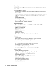
... Configuration Protocol (DHCP) v Wake on LAN v Wake on Ring (in the IBM Setup Utility program, this feature is called Serial Port Ring Detect for an external modem and Modem Ring Detect for an internal modem) v Remote Administration v Automatic power-on startup v System Management (SM) BIOS and SM software v Ability to support built-in , line out, and microphone) Expansion Two drive bays Power v 125 W power supply with preinstalled software. If it does, an operating system, device drivers...
... Configuration Protocol (DHCP) v Wake on LAN v Wake on Ring (in the IBM Setup Utility program, this feature is called Serial Port Ring Detect for an external modem and Modem Ring Detect for an internal modem) v Remote Administration v Automatic power-on startup v System Management (SM) BIOS and SM software v Ability to support built-in , line out, and microphone) Expansion Two drive bays Power v 125 W power supply with preinstalled software. If it does, an operating system, device drivers...

Hardware Maintenance Manual
Page 14
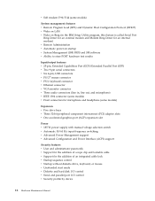
... v One accelerated graphics port (AGP) expansion slot (supports low-profile adapters only) Power v 160 W power supply with manual voltage selection switch v Automatic 50/60 Hz input frequency switching v Advanced Power Management support v Advanced Configuration and Power Interface (ACPI) support Security features v User and administrator passwords v Support for the addition of a rope clip and lockable cable v Support for the addition of an integrated cable lock v Startup sequence control v Startup without diskette drive, keyboard, or mouse v Unattended start mode 8 Hardware Maintenance Manual
... v One accelerated graphics port (AGP) expansion slot (supports low-profile adapters only) Power v 160 W power supply with manual voltage selection switch v Automatic 50/60 Hz input frequency switching v Advanced Power Management support v Advanced Configuration and Power Interface (ACPI) support Security features v User and administrator passwords v Support for the addition of a rope clip and lockable cable v Support for the addition of an integrated cable lock v Startup sequence control v Startup without diskette drive, keyboard, or mouse v Unattended start mode 8 Hardware Maintenance Manual
Hardware Maintenance Manual
Page 16
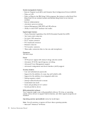
...pin, USB connectors v PS/2® mouse connector v PS/2 keyboard connector v Ethernet connector v VGA monitor connector v Three audio connectors (line in, line out, and microphone) Expansion v Four drive bays v Three 32-bit peripheral component interconnect (PCI) adapter slots v One accelerated graphics port (AGP) expansion slot Power v 185 W power supply with manual voltage selection switch v Automatic 50/60 Hz input frequency switching v Advanced Power Management support v Advanced Configuration and Power Interface (ACPI) support Security features v User and administrator passwords v Support...
...pin, USB connectors v PS/2® mouse connector v PS/2 keyboard connector v Ethernet connector v VGA monitor connector v Three audio connectors (line in, line out, and microphone) Expansion v Four drive bays v Three 32-bit peripheral component interconnect (PCI) adapter slots v One accelerated graphics port (AGP) expansion slot Power v 185 W power supply with manual voltage selection switch v Automatic 50/60 Hz input frequency switching v Advanced Power Management support v Advanced Configuration and Power Interface (ACPI) support Security features v User and administrator passwords v Support...
Hardware Maintenance Manual
Page 18
... (PCI) adapter slots v One accelerated graphics port (AGP) expansion slot Power v 185 W power supply with manual voltage selection switch v Automatic 50/60 Hz input frequency switching v Advanced Power Management support v Advanced Configuration and Power Interface (ACPI) support Security features v User and administrator passwords v Support for the addition of a rope clip and lockable cable v Support for the addition of an integrated cable lock v Startup sequence control v Startup without diskette drive, keyboard, or mouse v Unattended start mode v Diskette and hard disk I/O control v Serial...
... (PCI) adapter slots v One accelerated graphics port (AGP) expansion slot Power v 185 W power supply with manual voltage selection switch v Automatic 50/60 Hz input frequency switching v Advanced Power Management support v Advanced Configuration and Power Interface (ACPI) support Security features v User and administrator passwords v Support for the addition of a rope clip and lockable cable v Support for the addition of an integrated cable lock v Startup sequence control v Startup without diskette drive, keyboard, or mouse v Unattended start mode v Diskette and hard disk I/O control v Serial...
Hardware Maintenance Manual
Page 30
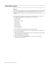
... to verify that the settings are servicing. When the Setup Utility prompt appears on the computer. 3. Power-off . 2. The Setup Utility menu will appear. 4. Note the current configuration settings and verify that any configuration changes have been accepted. 24 Hardware Maintenance Manual This program includes settings for the following: v System Summary v Product Data v Devices and I/O Ports v Start Options v Date and Time v System Security v Advanced Setup v Power Management To run the Setup Utility program, use lights go off the...
... to verify that the settings are servicing. When the Setup Utility prompt appears on the computer. 3. Power-off . 2. The Setup Utility menu will appear. 4. Note the current configuration settings and verify that any configuration changes have been accepted. 24 Hardware Maintenance Manual This program includes settings for the following: v System Summary v Product Data v Devices and I/O Ports v Start Options v Date and Time v System Security v Advanced Setup v Power Management To run the Setup Utility program, use lights go off the...

Hardware Maintenance Manual
Page 33
... the specified IBM computer. - Fixed-Disk Tests: v Seek Tests: - v DeviceID: Contains the component's unit-ID which the diagnostic test was run. Diagnostics were run on the PCI bus. checks the physical operation of the error. v ChkDigits: Contains a 2-digit check-digit value to change testing parameters FDAT consists of available devices and user specific configuration parameters located in PC Doctor for error code listings. FDAT will produce the following error code format: Function Code Failure Type DeviceID Date...
... the specified IBM computer. - Fixed-Disk Tests: v Seek Tests: - v DeviceID: Contains the component's unit-ID which the diagnostic test was run. Diagnostics were run on the PCI bus. checks the physical operation of the error. v ChkDigits: Contains a 2-digit check-digit value to change testing parameters FDAT consists of available devices and user specific configuration parameters located in PC Doctor for error code listings. FDAT will produce the following error code format: Function Code Failure Type DeviceID Date...
Hardware Maintenance Manual
Page 53
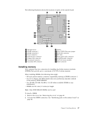
... the locations of parts on the system board. 1 Microprocessor 2 DIMM connector 1 3 DIMM connector 2 4 Power connector 5 Diskette drive connector 6 Primary IDE connector 7 Front panel connector 8 Secondary IDE connector 9 Battery 10 Clear CMOS/Recovery jumper 11 SCSI LED connector 12 PCI slots 13 Front panel audio connector 14 CD-ROM audio connector 15 AGP slot (some models) 16 Serial connector Installing memory Your computer has two connectors for installing dual inline memory modules (DIMMs) that provide up to a maximum of 2.0 GB of system memory. To install a DIMM: 1. Remove the cover. To...
... the locations of parts on the system board. 1 Microprocessor 2 DIMM connector 1 3 DIMM connector 2 4 Power connector 5 Diskette drive connector 6 Primary IDE connector 7 Front panel connector 8 Secondary IDE connector 9 Battery 10 Clear CMOS/Recovery jumper 11 SCSI LED connector 12 PCI slots 13 Front panel audio connector 14 CD-ROM audio connector 15 AGP slot (some models) 16 Serial connector Installing memory Your computer has two connectors for installing dual inline memory modules (DIMMs) that provide up to a maximum of 2.0 GB of system memory. To install a DIMM: 1. Remove the cover. To...

Hardware Maintenance Manual
Page 59
... panel installed. Chapter 5. When you install an internal drive, it is a removable-media drive, remove the bay panel from the front bezel. The following list describes some models) 3.5-inch hard disk drive (preinstalled) Notes: 1. Maximum height: 43.0 mm (1.7 in each bay. Installing Options 53 Internal drives are installing is important to correctly connect the internal drive cables to read other types of drive that your computer to as CD-ROM. The following illustration shows the locations of the drives...
... panel installed. Chapter 5. When you install an internal drive, it is a removable-media drive, remove the bay panel from the front bezel. The following list describes some models) 3.5-inch hard disk drive (preinstalled) Notes: 1. Maximum height: 43.0 mm (1.7 in each bay. Installing Options 53 Internal drives are installing is important to correctly connect the internal drive cables to read other types of drive that your computer to as CD-ROM. The following illustration shows the locations of the drives...

Hardware Maintenance Manual
Page 96
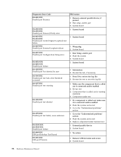
... error 001-026-XXX System FLASH data error 001-027-XXX System Configuration/Setup error 001-032-XXX System Device Controller failure 001-034-XXX System Device Buffer Allocation failure 001-035-XXX System Device Reset condition detected 001-036-XXX System Register error FRU/Action 1. System board 1. Flash the system 3. System board 1. Make sure the component that is connected and/or enabled 2. Flash the system and re-test 3. System board 1. System board 1. Re-run test...
... error 001-026-XXX System FLASH data error 001-027-XXX System Configuration/Setup error 001-032-XXX System Device Controller failure 001-034-XXX System Device Buffer Allocation failure 001-035-XXX System Device Reset condition detected 001-036-XXX System Register error FRU/Action 1. System board 1. Flash the system 3. System board 1. Make sure the component that is connected and/or enabled 2. Flash the system and re-test 3. System board 1. System board 1. Re-run test...

Hardware Maintenance Manual
Page 101
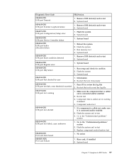
... called out is connected and/or enabled 2. External serial device 2. System board 011-015-XXX Serial port External Loopback failure 1. Run Setup, enable port 2. System board 014-000-XXX Parallel port Interface Test Passed 1. System board 011-002-XXX 011-003-XXX Serial port Timeout/Parity error 1. Make sure the component that is connected and/or enabled 2. Replace component under test 011-198-XXX Serial port test aborted 1. Re-run test 3. System board 011-195-XXX Serial port Test aborted by user 1. Run setup, enable port 3. Re-start the test, if necessary...
... called out is connected and/or enabled 2. External serial device 2. System board 011-015-XXX Serial port External Loopback failure 1. Run Setup, enable port 2. System board 014-000-XXX Parallel port Interface Test Passed 1. System board 011-002-XXX 011-003-XXX Serial port Timeout/Parity error 1. Make sure the component that is connected and/or enabled 2. Replace component under test 011-198-XXX Serial port test aborted 1. Re-run test 3. System board 011-195-XXX Serial port Test aborted by user 1. Run setup, enable port 3. Re-start the test, if necessary...
Hardware Maintenance Manual
Page 102
..., if present 2. System board 1. Run Setup, enable port 2. Make sure the component that is connected and/or enabled 2. Re-run test 3. Go to reset the log file 1. System board 96 Hardware Maintenance Manual Information 2. Component that is called out, make sure it is called out in warning statement 4. Component under function test 1. No action 1. System board 1. External parallel device 2. System board 1. Flash the system 3. Remove USB device(s) and re-test 2. Wrap plug 2. Run setup, enable port 3. System board 1. Diagnostic Error Code 014-001-XXX...
..., if present 2. System board 1. Run Setup, enable port 2. Make sure the component that is connected and/or enabled 2. Re-run test 3. Go to reset the log file 1. System board 96 Hardware Maintenance Manual Information 2. Component that is called out, make sure it is called out in warning statement 4. Component under function test 1. No action 1. System board 1. External parallel device 2. System board 1. Flash the system 3. Remove USB device(s) and re-test 2. Wrap plug 2. Run setup, enable port 3. System board 1. Diagnostic Error Code 014-001-XXX...
Hardware Maintenance Manual
Page 103
... board 1. Flash the system and re-test 3. System board 1. Remove USB device(s) and re-test 2. Re-start the test to reset the log file 1. If a component is called out is connected and/or enabled 2. Go to -FRU Index 97 Information 2. Flash the system 3. Symptom-to the ″Undetermined problems″ section 2. Diagnostic Error Code 015-002-XXX USB port Timeout 015-015-XXX USB port External Loopback failure 015-027-XXX USB port Configuration/Setup error 015-032-XXX USB port Device Controller failure...
... board 1. Flash the system and re-test 3. System board 1. Remove USB device(s) and re-test 2. Re-start the test to reset the log file 1. If a component is called out is connected and/or enabled 2. Go to -FRU Index 97 Information 2. Flash the system 3. Symptom-to the ″Undetermined problems″ section 2. Diagnostic Error Code 015-002-XXX USB port Timeout 015-015-XXX USB port External Loopback failure 015-027-XXX USB port Configuration/Setup error 015-032-XXX USB port Device Controller failure...

Hardware Maintenance Manual
Page 107
... problems″ section 2. Re-run test 3. Go to review the log file 2. Run Setup 2. Speakers 2. Replace component under test 1. Flash the system and re-test 3. System board 1. Audio card, if installed 3. Component under test 1. Re-start the test, if necessary 1. Symptom-to reset the log file 1. Re-start the test to -FRU Index 101 Information 2. Run Setup 2. Press F3 to reset the log file 1. Diagnostic Error Code 035-196-XXX RAID interface test halt, error threshold exceeded 035-197-XXX RAID...
... problems″ section 2. Re-run test 3. Go to review the log file 2. Run Setup 2. Speakers 2. Replace component under test 1. Flash the system and re-test 3. System board 1. Audio card, if installed 3. Component under test 1. Re-start the test, if necessary 1. Symptom-to reset the log file 1. Re-start the test to -FRU Index 101 Information 2. Run Setup 2. Press F3 to reset the log file 1. Diagnostic Error Code 035-196-XXX RAID interface test halt, error threshold exceeded 035-197-XXX RAID...
Hardware Maintenance Manual
Page 117
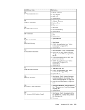
... Configuration 2. Power-on external devices first, then power-on page 267. 2. Run Setup. Processor 2. System board 1. Run Setup 2. Run the Extended Memory Diagnostic tests 1. Riser card 4. L2 Cache Memory 3. System Board 1. Had a device been added, removed, changed location? Time and Date Set 2. Fan 2. See "Flash recovery boot block jumper" on computer 4. Symptom-to-FRU Index 111 POST Error Code 111 I/O channel parity error 114 Adapter ROM error 129 Internal cache test error 135 Fan failure 151 System board failure 161 Bad CMOS battery 162 Configuration...
... Configuration 2. Power-on external devices first, then power-on page 267. 2. Run Setup. Processor 2. System board 1. Run Setup 2. Run the Extended Memory Diagnostic tests 1. Riser card 4. L2 Cache Memory 3. System Board 1. Had a device been added, removed, changed location? Time and Date Set 2. Fan 2. See "Flash recovery boot block jumper" on computer 4. Symptom-to-FRU Index 111 POST Error Code 111 I/O channel parity error 114 Adapter ROM error 129 Internal cache test error 135 Fan failure 151 System board failure 161 Bad CMOS battery 162 Configuration...

Hardware Maintenance Manual
Page 118
... 3. System Board 1. System Board 1. System Board 1. System Board 1. Check to access the computer 1. See "Setup Utility program" on LAN are enabled in Configuration/Setup 2. System Board 1. Enter the administrator password 1. Run Enhanced Diagnostics Memory Test 2. Run Configuration. System Board 1. System Board 112 Hardware Maintenance Manual System Board 1. More than three password attempts were made to see that Ethernet and Alert on page 24. 2. C2 Security 1. System Board 1. Memory Module 3. POST Error Code 168 Alert on LAN error 17X, 18X...
... 3. System Board 1. System Board 1. System Board 1. System Board 1. Check to access the computer 1. See "Setup Utility program" on LAN are enabled in Configuration/Setup 2. System Board 1. Enter the administrator password 1. Run Enhanced Diagnostics Memory Test 2. Run Configuration. System Board 1. System Board 112 Hardware Maintenance Manual System Board 1. More than three password attempts were made to see that Ethernet and Alert on page 24. 2. C2 Security 1. System Board 1. Memory Module 3. POST Error Code 168 Alert on LAN error 17X, 18X...
Hardware Maintenance Manual
Page 132
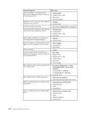
Diskette Drive Cable 3. Network Adapter Intensity or color varies from its own hard disk. 1. See "Power Supply Errors" on , but computer works correctly 2. Power Supply light not on page 87. Diskette Drive 3. Power Supply RPL computer cannot access programs from left to right of 1. If network administrator is using LCCM Hybrid RPL, check startup sequence: a. Check the network adapter LED status Serial or parallel port device failure (system board port) 1. External Device 3. System Board 126 Hardware Maintenance Manual Message/Symptom FRU/Action ″Insert a Diskette...
Diskette Drive Cable 3. Network Adapter Intensity or color varies from its own hard disk. 1. See "Power Supply Errors" on , but computer works correctly 2. Power Supply light not on page 87. Diskette Drive 3. Power Supply RPL computer cannot access programs from left to right of 1. If network administrator is using LCCM Hybrid RPL, check startup sequence: a. Check the network adapter LED status Serial or parallel port device failure (system board port) 1. External Device 3. System Board 126 Hardware Maintenance Manual Message/Symptom FRU/Action ″Insert a Diskette...
Hardware Maintenance Manual
Page 269
... the password. 5. Removing a power-on password To service a computer with an active and unknown power-on the computer. The system senses the change in the Setup Utility program. See "Setup Utility program" on page 44 to sound, and then power down by an unauthorized user when the computer is entered. Refer to "Identifying parts on the system board" on page 24 for beeps to find the Virtual clear CMOS/BIOS recovery jumper. 3. Administrator password...
... the password. 5. Removing a power-on password To service a computer with an active and unknown power-on the computer. The system senses the change in the Setup Utility program. See "Setup Utility program" on page 44 to sound, and then power down by an unauthorized user when the computer is entered. Refer to "Identifying parts on the system board" on page 24 for beeps to find the Virtual clear CMOS/BIOS recovery jumper. 3. Administrator password...


