Hardware Maintenance Manual
Page 5
... Installing memory 47 Installing adapters 48 Installing internal drives 52 Installing a rope clip 64 Changing the battery 67 Replacing the cover and connecting the cables. . 67 Chapter 6. Diagnostics 23 Setup Utility program 24 Product Recovery Program menu 25 Diagnostics 26 Diagnostics program download 26 Navigating through the diagnostics programs . . 26 Running diagnostics tests 26 Test selection 26 Test results 27 Fixed disk advanced test (FDAT 27 Quick and Full erase - Symptom-to-FRU Index . . . 87 Hard disk drive boot error 87 Power Supply Errors 87 Diagnostic error codes...
... Installing memory 47 Installing adapters 48 Installing internal drives 52 Installing a rope clip 64 Changing the battery 67 Replacing the cover and connecting the cables. . 67 Chapter 6. Diagnostics 23 Setup Utility program 24 Product Recovery Program menu 25 Diagnostics 26 Diagnostics program download 26 Navigating through the diagnostics programs . . 26 Running diagnostics tests 26 Test selection 26 Test results 27 Fixed disk advanced test (FDAT 27 Quick and Full erase - Symptom-to-FRU Index . . . 87 Hard disk drive boot error 87 Power Supply Errors 87 Diagnostic error codes...
Hardware Maintenance Manual
Page 9
... external devices. 2. Check for Types 8301, 8302, 8303, 8304, 8305, 8306, 8307, 8308, 8309, 8310, 8311, 8312, 8313, 8314, and 8315 computers. Attention: The drives in the Configuration/Setup Utility program (see "BIOS levels" on the computer. 7. v To enable beep and memory count and checkpoint code display when a successful POST occurs, do the following response: v Readable instructions or the Main Menu. © Copyright IBM Corp. 2001 3 Select Start Options...
... external devices. 2. Check for Types 8301, 8302, 8303, 8304, 8305, 8306, 8307, 8308, 8309, 8310, 8311, 8312, 8313, 8314, and 8315 computers. Attention: The drives in the Configuration/Setup Utility program (see "BIOS levels" on the computer. 7. v To enable beep and memory count and checkpoint code display when a successful POST occurs, do the following response: v Readable instructions or the Main Menu. © Copyright IBM Corp. 2001 3 Select Start Options...
Hardware Maintenance Manual
Page 11
... solve problems and get repair service or other technical assistance. When adding an option, use , operation, and maintenance of internal L2 cache memory and Intel NetBurst™ micro-architecture Memory v Support for two dual inline memory modules (DIMMs) v 512 KB flash memory for system programs Internal drives v Internal hard disk drive Note: The hard disk drive should only be upgraded as your computer is an easy way to your needs change. v EIDE CD-ROM drive (some models) Video subsystem Intel Extreme™ graphics Audio subsystem...
... solve problems and get repair service or other technical assistance. When adding an option, use , operation, and maintenance of internal L2 cache memory and Intel NetBurst™ micro-architecture Memory v Support for two dual inline memory modules (DIMMs) v 512 KB flash memory for system programs Internal drives v Internal hard disk drive Note: The hard disk drive should only be upgraded as your computer is an easy way to your needs change. v EIDE CD-ROM drive (some models) Video subsystem Intel Extreme™ graphics Audio subsystem...
Hardware Maintenance Manual
Page 12
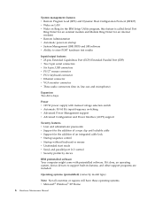
...174; Windows® XP Home 6 Hardware Maintenance Manual Operating systems (preinstalled) (varies by device IBM preinstalled software Your computer might come with preinstalled software. If it does, an operating system, device drivers to store POST hardware test results Input/output features v 25-pin, Extended Capabilities Port (ECP)/Extended Parallel Port (EPP) v Two 9-pin serial connectors v Six 4-pin, USB connectors v PS/2® mouse connector v PS/2 keyboard connector v Ethernet connector v VGA monitor connector v Three audio connectors (line in features, and other support programs...
...174; Windows® XP Home 6 Hardware Maintenance Manual Operating systems (preinstalled) (varies by device IBM preinstalled software Your computer might come with preinstalled software. If it does, an operating system, device drivers to store POST hardware test results Input/output features v 25-pin, Extended Capabilities Port (ECP)/Extended Parallel Port (EPP) v Two 9-pin serial connectors v Six 4-pin, USB connectors v PS/2® mouse connector v PS/2 keyboard connector v Ethernet connector v VGA monitor connector v Three audio connectors (line in features, and other support programs...

Hardware Maintenance Manual
Page 14
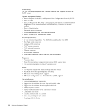
... v One accelerated graphics port (AGP) expansion slot (supports low-profile adapters only) Power v 160 W power supply with manual voltage selection switch v Automatic 50/60 Hz input frequency switching v Advanced Power Management support v Advanced Configuration and Power Interface (ACPI) support Security features v User and administrator passwords v Support for the addition of a rope clip and lockable cable v Support for the addition of an integrated cable lock v Startup sequence control v Startup without diskette drive, keyboard, or mouse v Unattended start mode 8 Hardware Maintenance Manual
... v One accelerated graphics port (AGP) expansion slot (supports low-profile adapters only) Power v 160 W power supply with manual voltage selection switch v Automatic 50/60 Hz input frequency switching v Advanced Power Management support v Advanced Configuration and Power Interface (ACPI) support Security features v User and administrator passwords v Support for the addition of a rope clip and lockable cable v Support for the addition of an integrated cable lock v Startup sequence control v Startup without diskette drive, keyboard, or mouse v Unattended start mode 8 Hardware Maintenance Manual
Hardware Maintenance Manual
Page 16
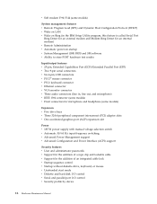
...pin, USB connectors v PS/2® mouse connector v PS/2 keyboard connector v Ethernet connector v VGA monitor connector v Three audio connectors (line in, line out, and microphone) Expansion v Four drive bays v Three 32-bit peripheral component interconnect (PCI) adapter slots v One accelerated graphics port (AGP) expansion slot Power v 185 W power supply with manual voltage selection switch v Automatic 50/60 Hz input frequency switching v Advanced Power Management support v Advanced Configuration and Power Interface (ACPI) support Security features v User and administrator passwords v Support...
...pin, USB connectors v PS/2® mouse connector v PS/2 keyboard connector v Ethernet connector v VGA monitor connector v Three audio connectors (line in, line out, and microphone) Expansion v Four drive bays v Three 32-bit peripheral component interconnect (PCI) adapter slots v One accelerated graphics port (AGP) expansion slot Power v 185 W power supply with manual voltage selection switch v Automatic 50/60 Hz input frequency switching v Advanced Power Management support v Advanced Configuration and Power Interface (ACPI) support Security features v User and administrator passwords v Support...
Hardware Maintenance Manual
Page 18
... (PCI) adapter slots v One accelerated graphics port (AGP) expansion slot Power v 185 W power supply with manual voltage selection switch v Automatic 50/60 Hz input frequency switching v Advanced Power Management support v Advanced Configuration and Power Interface (ACPI) support Security features v User and administrator passwords v Support for the addition of a rope clip and lockable cable v Support for the addition of an integrated cable lock v Startup sequence control v Startup without diskette drive, keyboard, or mouse v Unattended start mode v Diskette and hard disk I/O control v Serial...
... (PCI) adapter slots v One accelerated graphics port (AGP) expansion slot Power v 185 W power supply with manual voltage selection switch v Automatic 50/60 Hz input frequency switching v Advanced Power Management support v Advanced Configuration and Power Interface (ACPI) support Security features v User and administrator passwords v Support for the addition of a rope clip and lockable cable v Support for the addition of an integrated cable lock v Startup sequence control v Startup without diskette drive, keyboard, or mouse v Unattended start mode v Diskette and hard disk I/O control v Serial...
Hardware Maintenance Manual
Page 30
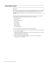
... -use lights go off the computer and wait for the following: v System Summary v Product Data v Devices and I/O Ports v Start Options v Date and Time v System Security v Advanced Setup v Power Management To run the Setup Utility program, use the following procedure. 1. When the Setup Utility prompt appears on the computer. 3. Power-on the screen during start-up, press F1. Follow the instructions on the screen. 5. Power-off . 2. Setup Utility program Attention: A customized setup configuration (other than default settings) might...
... -use lights go off the computer and wait for the following: v System Summary v Product Data v Devices and I/O Ports v Start Options v Date and Time v System Security v Advanced Setup v Power Management To run the Setup Utility program, use the following procedure. 1. When the Setup Utility prompt appears on the computer. 3. Power-on the screen during start-up, press F1. Follow the instructions on the screen. 5. Power-off . 2. Setup Utility program Attention: A customized setup configuration (other than default settings) might...

Hardware Maintenance Manual
Page 33
... CMOS and displayed using the YYYYMMDD format. FDAT uses information supplied by >>. Linear Seek Chapter 4. Repeat steps 2 and 3 above to either a fixed disk drive, removable media drive, serial or parallel port, processor, specific RIMM, or a device on page 89 for the device, device properties, etc. v DeviceID: Contains the component's unit-ID which the diagnostic test was run on the specified date. - v Text: Description of FDAT allow users to enable or disable specific tests, enable or disable testing features, control...
... CMOS and displayed using the YYYYMMDD format. FDAT uses information supplied by >>. Linear Seek Chapter 4. Repeat steps 2 and 3 above to either a fixed disk drive, removable media drive, serial or parallel port, processor, specific RIMM, or a device on page 89 for the device, device properties, etc. v DeviceID: Contains the component's unit-ID which the diagnostic test was run on the specified date. - v Text: Description of FDAT allow users to enable or disable specific tests, enable or disable testing features, control...

Hardware Maintenance Manual
Page 59
... following list describes some models) v A 3.5-inch hard disk drive in each bay and their height requirements: 1 Bay 1 - Maximum height: 43.0 mm (1.7 in .) high cannot be installed. 2. Drives that you install an internal drive, it is a removable-media drive, remove the bay panel from the front bezel. Types 8303, 8304, and 8312 This section provides information and instructions for installing and removing internal drives. The following IBM-installed drives: v A 3.5-inch diskette drive in bay 1 v A CD-ROM drive or DVD-ROM drive in...
... following list describes some models) v A 3.5-inch hard disk drive in each bay and their height requirements: 1 Bay 1 - Maximum height: 43.0 mm (1.7 in .) high cannot be installed. 2. Drives that you install an internal drive, it is a removable-media drive, remove the bay panel from the front bezel. Types 8303, 8304, and 8312 This section provides information and instructions for installing and removing internal drives. The following IBM-installed drives: v A 3.5-inch diskette drive in bay 1 v A CD-ROM drive or DVD-ROM drive in...
Hardware Maintenance Manual
Page 73
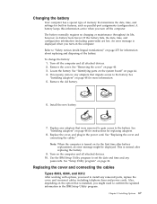
... replacing the battery. 9. Replacing the cover and connecting the cables Types 8303, 8304, and 8312 After working with options, you turn on page 275 for more information. 5. however, no charging or maintenance throughout its life; To change the battery: 1. See "Installing adapters" on page 24. Replace any passwords. See "Setup Utility program" on page 48 for information about replacing and disposing of memory that impede access to confirm the updated information in the power cord. A battery...
... replacing the battery. 9. Replacing the cover and connecting the cables Types 8303, 8304, and 8312 After working with options, you turn on page 275 for more information. 5. however, no charging or maintenance throughout its life; To change the battery: 1. See "Installing adapters" on page 24. Replace any passwords. See "Setup Utility program" on page 48 for information about replacing and disposing of memory that impede access to confirm the updated information in the power cord. A battery...

Hardware Maintenance Manual
Page 96
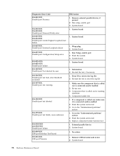
... Configuration/Setup error 001-032-XXX System Device Controller failure 001-034-XXX System Device Buffer Allocation failure 001-035-XXX System Device Reset condition detected 001-036-XXX System Register error FRU/Action 1. Component under function test 1. Flash the system and re-test 3. Flash the system 2. System board 1. System board 1. System board 1. Reboot the system 2. Flash the system 3. System board 1. No action 1. If a component is called out is connected and/or enabled...
... Configuration/Setup error 001-032-XXX System Device Controller failure 001-034-XXX System Device Buffer Allocation failure 001-035-XXX System Device Reset condition detected 001-036-XXX System Register error FRU/Action 1. Component under function test 1. Flash the system and re-test 3. Flash the system 2. System board 1. System board 1. System board 1. Reboot the system 2. Flash the system 3. System board 1. No action 1. If a component is called out is connected and/or enabled...

Hardware Maintenance Manual
Page 101
...Remove external serial device, if present 2. Run setup, enable port 3. Information 2. If a component is called out is connected and/or enabled 2. External serial device 2. Diagnostic Error Code FRU/Action 011-000-XXX Serial port Interface Test Passed 1. Wrap plug 2. Flash the system 3. Make sure the component that is connected and/or enabled 2. Re-run test 3. Symptom-to review the log file Serial port test halt, error threshold exceeded 2. System board 011-015-XXX Serial port External Loopback failure 1. Component under function test 011-2XX-XXX Serial...
...Remove external serial device, if present 2. Run setup, enable port 3. Information 2. If a component is called out is connected and/or enabled 2. External serial device 2. Diagnostic Error Code FRU/Action 011-000-XXX Serial port Interface Test Passed 1. Wrap plug 2. Flash the system 3. Make sure the component that is connected and/or enabled 2. Re-run test 3. Symptom-to review the log file Serial port test halt, error threshold exceeded 2. System board 011-015-XXX Serial port External Loopback failure 1. Component under function test 011-2XX-XXX Serial...
Hardware Maintenance Manual
Page 102
... Hardware Maintenance Manual System board 1. Make sure the component that is connected and/or enabled 2. If a component is called out is called out in warning statement 4. No action 1. Remove USB device(s) and re-test 2. Diagnostic Error Code 014-001-XXX Parallel port Presence 014-002-XXX 014-003-XXX Parallel port Timeout/Parity error 014-013-XXX 014-014-XXX Parallel port Control Signal/Loopback test failure 014-015-XXX Parallel port External...
... Hardware Maintenance Manual System board 1. Make sure the component that is connected and/or enabled 2. If a component is called out is called out in warning statement 4. No action 1. Remove USB device(s) and re-test 2. Diagnostic Error Code 014-001-XXX Parallel port Presence 014-002-XXX 014-003-XXX Parallel port Timeout/Parity error 014-013-XXX 014-014-XXX Parallel port Control Signal/Loopback test failure 014-015-XXX Parallel port External...
Hardware Maintenance Manual
Page 103
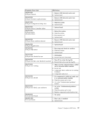
... board 1. System board 1. Flash the system 3. Remove USB device(s) and re-test 2. Flash the system 3. System board 1. Make sure the component that is connected and/or enabled 2. Replace component under test 1. System board Chapter 7. Diagnostic Error Code 015-002-XXX USB port Timeout 015-015-XXX USB port External Loopback failure 015-027-XXX USB port Configuration/Setup error 015-032-XXX USB port Device Controller failure 015-034-XXX USB port buffer allocation failure 015-035-XXX USB port Reset condition detected 015-036-XXX USB port Register error 015-040-XXX USB port...
... board 1. System board 1. Flash the system 3. Remove USB device(s) and re-test 2. Flash the system 3. System board 1. Make sure the component that is connected and/or enabled 2. Replace component under test 1. System board Chapter 7. Diagnostic Error Code 015-002-XXX USB port Timeout 015-015-XXX USB port External Loopback failure 015-027-XXX USB port Configuration/Setup error 015-032-XXX USB port Device Controller failure 015-034-XXX USB port buffer allocation failure 015-035-XXX USB port Reset condition detected 015-036-XXX USB port Register error 015-040-XXX USB port...

Hardware Maintenance Manual
Page 107
...-02X-XXX Audio port error 071-03X-XXX Audio port failure 071-04X-XXX Audio port failure 071-195-XXX Audio port Test aborted by user 071-196-XXX Audio port test halt, error threshold exceeded 071-197-XXX Audio port test warning 071-198-XXX Audio port test aborted FRU/Action 1. Re-run test 3. Replace component under test 1. Flash the system 3. Make sure the component that is called out is connected and/or enabled 2. Re-run test 3. Component under function test 1. Make sure the...
...-02X-XXX Audio port error 071-03X-XXX Audio port failure 071-04X-XXX Audio port failure 071-195-XXX Audio port Test aborted by user 071-196-XXX Audio port test halt, error threshold exceeded 071-197-XXX Audio port test warning 071-198-XXX Audio port test aborted FRU/Action 1. Re-run test 3. Replace component under test 1. Flash the system 3. Make sure the component that is called out is connected and/or enabled 2. Re-run test 3. Component under function test 1. Make sure the...
Hardware Maintenance Manual
Page 117
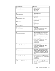
...Adapter Memory 2. Processor 2. Fan 2. System Board 1. L2 Cache Memory 3. System Board 1. POST Error Code 111 I/O channel parity error 114 Adapter ROM error 129 Internal cache test error 135 Fan failure 151 System board failure 161 Bad CMOS battery 162 Configuration mismatch 163 Date and Time Incorrect 164 Memory Size Error 166 Boot Block Check Sum Error 167 No Processor BIOS Update Found FRU/Action 1. Riser card 1. Run Setup 2. System Board 1. CMOS Backup Battery (see "Safety information" on page 267. 2. Run Flash Recovery using Boot Block. See "Flash recovery boot block jumper...
...Adapter Memory 2. Processor 2. Fan 2. System Board 1. L2 Cache Memory 3. System Board 1. POST Error Code 111 I/O channel parity error 114 Adapter ROM error 129 Internal cache test error 135 Fan failure 151 System board failure 161 Bad CMOS battery 162 Configuration mismatch 163 Date and Time Incorrect 164 Memory Size Error 166 Boot Block Check Sum Error 167 No Processor BIOS Update Found FRU/Action 1. Riser card 1. Run Setup 2. System Board 1. CMOS Backup Battery (see "Safety information" on page 267. 2. Run Flash Recovery using Boot Block. See "Flash recovery boot block jumper...

Hardware Maintenance Manual
Page 118
... Security: Invalid Remote Change Requested 191 System Security: IBM Embedded Security Hardware Reset 193 System Security: IBM Embedded Security Hardware Removed 194 System Security: Asset ID Antenna has been Removed 195 System Security: Asset ID Antenna has been Installed 196 System Tampered Cleared 1XX Not listed above 201, 20X Memory data error FRU/Action 1. System Board 1. System Board 1. Enter the administrator password 1. System Board 1. System Board 1. System Board 1. Run Enhanced Diagnostics Memory Test 2. System Board 112 Hardware Maintenance Manual
... Security: Invalid Remote Change Requested 191 System Security: IBM Embedded Security Hardware Reset 193 System Security: IBM Embedded Security Hardware Removed 194 System Security: Asset ID Antenna has been Removed 195 System Security: Asset ID Antenna has been Installed 196 System Tampered Cleared 1XX Not listed above 201, 20X Memory data error FRU/Action 1. System Board 1. System Board 1. Enter the administrator password 1. System Board 1. System Board 1. System Board 1. Run Enhanced Diagnostics Memory Test 2. System Board 112 Hardware Maintenance Manual
Hardware Maintenance Manual
Page 132
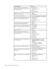
...or color varies from its own hard disk. 1. Non-system disk or disk error-type message with a known-good diagnostics diskette in the first 3.5-inch diskette drive. 1. System Board 3. System Board 5. Power Supply RPL computer cannot access programs from left to right of 1. Check startup sequence 2. System Board Serial or parallel port device failure (adapter 1. External Device Self-Test OK? port) 2. Alternate Adapter 5. Riser card 4. Diskette Drive Cable 4. LED Cables Printer problems 1. Run Setup 2. If network administrator is using LCCM Hybrid RPL, check...
...or color varies from its own hard disk. 1. Non-system disk or disk error-type message with a known-good diagnostics diskette in the first 3.5-inch diskette drive. 1. System Board 3. System Board 5. Power Supply RPL computer cannot access programs from left to right of 1. Check startup sequence 2. System Board Serial or parallel port device failure (adapter 1. External Device Self-Test OK? port) 2. Alternate Adapter 5. Riser card 4. Diskette Drive Cable 4. LED Cables Printer problems 1. Run Setup 2. If network administrator is using LCCM Hybrid RPL, check...
Hardware Maintenance Manual
Page 269
... also remove the administrator password. 1. v Power-on Password v Administrator Password v Operating System Password Power-on LAN Passwords The following procedure. Wait 30 seconds for beeps to find the Virtual clear CMOS/BIOS recovery jumper. 3. Chapter 9. Refer to enter a new password when service is activated, and you do not enter the administrator password, the configuration can be viewed but not changed. © Copyright IBM Corp. 2001 263 Reset the date and time and remind the user to "Identifying parts...
... also remove the administrator password. 1. v Power-on Password v Administrator Password v Operating System Password Power-on LAN Passwords The following procedure. Wait 30 seconds for beeps to find the Virtual clear CMOS/BIOS recovery jumper. 3. Chapter 9. Refer to enter a new password when service is activated, and you do not enter the administrator password, the configuration can be viewed but not changed. © Copyright IBM Corp. 2001 263 Reset the date and time and remind the user to "Identifying parts...


