
User Guide
Page 5
...the cables . . . 24 Chapter 3. Replacing customer replaceable units (CRU 29 CRU list 30 Removing and replacing the power supply assembly 31 Removing and replacing the system board assembly 34 Removing the microprocessor 36 Replacing the microprocessor 38 Removing and replacing ...7 Handling static-sensitive devices 7 Installing external options 7 Locating controls and connectors on the front of your operating system 45 Recovering from the IBM Setup Utility program . . . 26 Using passwords 26 User password 26 Administrator password 26 Setting, changing, and deleting a password . ....
...the cables . . . 24 Chapter 3. Replacing customer replaceable units (CRU 29 CRU list 30 Removing and replacing the power supply assembly 31 Removing and replacing the system board assembly 34 Removing the microprocessor 36 Replacing the microprocessor 38 Removing and replacing ...7 Handling static-sensitive devices 7 Installing external options 7 Locating controls and connectors on the front of your operating system 45 Recovering from the IBM Setup Utility program . . . 26 Using passwords 26 User password 26 Administrator password 26 Setting, changing, and deleting a password . ....
User Guide
Page 7
... you have any question about the condition of a component, do not take risks or attempt to IBM. v Power cords, plugs, power adapters, extension cords, surge protectors, or power supplies that are electronic devices. Follow and retain all information included with any electronic device, pay close attention... manner. Or you can become damaged due to inspect the product and have any safety concerns with external power adapters. However, do not use your IBM computer. v Signs of smoke or sparks vent from hazards and create a safer computer work environment. Our...
... you have any question about the condition of a component, do not take risks or attempt to IBM. v Power cords, plugs, power adapters, extension cords, surge protectors, or power supplies that are electronic devices. Follow and retain all information included with any electronic device, pay close attention... manner. Or you can become damaged due to inspect the product and have any safety concerns with external power adapters. However, do not use your IBM computer. v Signs of smoke or sparks vent from hazards and create a safer computer work environment. Our...

User Guide
Page 8
... fray, crack or crimp. These parts are securely and completely plugged into receptacles. Power cords and power adapters Use only the power cords and power adapters supplied by the customer. Use only an IBM authorized service provider who is unplugged from the product. Doing so can present a ...or an object has fallen onto the computer product, the power cord or power adapter. v Signs that comes from any way. v The computer product, the power cord or power adapter has been exposed to water. IBM expressly identifies CRUs as such, and provides documentation with liquid...
... fray, crack or crimp. These parts are securely and completely plugged into receptacles. Power cords and power adapters Use only the power cords and power adapters supplied by the customer. Use only an IBM authorized service provider who is unplugged from the product. Doing so can present a ...or an object has fallen onto the computer product, the power cord or power adapter. v Signs that comes from any way. v The computer product, the power cord or power adapter has been exposed to water. IBM expressly identifies CRUs as such, and provides documentation with liquid...
User Guide
Page 9
...and/or shows signs of Important safety information vii Extension cords and related devices Ensure that extension cords, surge protectors, uninterruptible power supplies, and power strips that you have been tested for use with your battery or the buildup of overheating (such as Thinkpad notebook PCs ... ratings. Never overload an electrical outlet. Consult an electrician for more information if you intend to use with IBM approved parts. Do not fully extend power cords in any way. Never attempt to instructions included in portable mode. If your battery is damaged, contact...
...and/or shows signs of Important safety information vii Extension cords and related devices Ensure that extension cords, surge protectors, uninterruptible power supplies, and power strips that you have been tested for use with your battery or the buildup of overheating (such as Thinkpad notebook PCs ... ratings. Never overload an electrical outlet. Consult an electrician for more information if you intend to use with IBM approved parts. Do not fully extend power cords in any way. Never attempt to instructions included in portable mode. If your battery is damaged, contact...
User Guide
Page 17
... PCI full height adapter slots v Two DIMM memory connectors Power v 200 Watt power supply with manual voltage selection switch v Automatic 50/60 Hz input frequency switching v Advanced Power Management support v Advanced Configuration and Power Interface (ACPI) support Security features v User and administrator ...keyboard, or mouse v Diskette and hard disk I/O control v Serial and parallel port I/O control v Security profile by device IBM preinstalled software Your computer comes with preinstalled software. An operating system, device drivers to store POST hardware test results Input/output ...
... PCI full height adapter slots v Two DIMM memory connectors Power v 200 Watt power supply with manual voltage selection switch v Automatic 50/60 Hz input frequency switching v Advanced Power Management support v Advanced Configuration and Power Interface (ACPI) support Security features v User and administrator ...keyboard, or mouse v Diskette and hard disk I/O control v Serial and parallel port I/O control v Security profile by device IBM preinstalled software Your computer comes with preinstalled software. An operating system, device drivers to store POST hardware test results Input/output ...

User Guide
Page 25
Installing options 11 Locating components The following illustration will help you locate the various components in your computer. 1 Diskette drive lock 2 DIMM (memory) connectors (2) 3 Battery 4 PCI riser 5 Power supply assembly 6 CD or DVD drive (hard disk drive is under the CD drive) 7 CD or DVD drive lock Chapter 2.
Installing options 11 Locating components The following illustration will help you locate the various components in your computer. 1 Diskette drive lock 2 DIMM (memory) connectors (2) 3 Battery 4 PCI riser 5 Power supply assembly 6 CD or DVD drive (hard disk drive is under the CD drive) 7 CD or DVD drive lock Chapter 2.
User Guide
Page 27
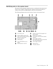
... are IBM-installed or that you can install later. Identifying parts on the system board. 1 Fan connectors (2) 8 Promise of value (POV) daughter card (some models) 2 Memory DIMM connectors (2) 9 Diskette drive connector 3 SATA 1 IDE and SATA 2 IDE hard 10 Power button and front LED assembly disk drive connectors (2) connector 4 PCI riser connector 11 Power supply...
... are IBM-installed or that you can install later. Identifying parts on the system board. 1 Fan connectors (2) 8 Promise of value (POV) daughter card (some models) 2 Memory DIMM connectors (2) 9 Diskette drive connector 3 SATA 1 IDE and SATA 2 IDE hard 10 Power button and front LED assembly disk drive connectors (2) connector 4 PCI riser connector 11 Power supply...

User Guide
Page 31
Installing options 17 Each drive also requires the connection of drives and the connector used to connect them to the diskette drive connector Chapter 2. Parallel ATA IDE drive Serial ATA IDE drive Listed below are the various types of a power cable from the power supply. Serial ATA IDE hard disk drive Connect to an SATA 1 IDE or SATA 2 IDE connector Parallel ATA IDE hard disk drive Connect to the PATA Primary IDE connector CD-ROM, CD-RW, or DVD optical drives Connect to the PATA Primary IDE connector Diskette drive Connect to the system board.
Installing options 17 Each drive also requires the connection of drives and the connector used to connect them to the diskette drive connector Chapter 2. Parallel ATA IDE drive Serial ATA IDE drive Listed below are the various types of a power cable from the power supply. Serial ATA IDE hard disk drive Connect to an SATA 1 IDE or SATA 2 IDE connector Parallel ATA IDE hard disk drive Connect to the PATA Primary IDE connector CD-ROM, CD-RW, or DVD optical drives Connect to the PATA Primary IDE connector Diskette drive Connect to the system board.
User Guide
Page 43
...CRU) Some computer models are designed to : http://www.ibm.com/pc/support To replace some CRUs in your computer after the power cord has been disconnected, the following CRUs: v power supply v microprocessor v system board v battery v speaker v fan v power button and LED assembly For memory DIMMs, PCI adapters, ... Maintenance manual (HMM) for your computer, you when replacing the following warning is important when installing new CRUs. © Copyright IBM Corp. 2004 29 These procedures are available from the World Wide Web. If you have Internet access, the most up-to guide...
...CRU) Some computer models are designed to : http://www.ibm.com/pc/support To replace some CRUs in your computer after the power cord has been disconnected, the following CRUs: v power supply v microprocessor v system board v battery v speaker v fan v power button and LED assembly For memory DIMMs, PCI adapters, ... Maintenance manual (HMM) for your computer, you when replacing the following warning is important when installing new CRUs. © Copyright IBM Corp. 2004 29 These procedures are available from the World Wide Web. If you have Internet access, the most up-to guide...

User Guide
Page 44
CRU list Battery, CMOS Bezel, front plastic Kit Cables, all Cover Cover lock assembly Diskette drive Fan assembly Floor stand Hard disk drives Hard disk drive bracket Keyboard Memory DIMMs Microprocessor Microprocessor heat sink Mouse Optical drives Phone line cord Power button and LED assembly Power supply, 200 Watt Riser card assembly RJ11 connector adapter Rotating drive bay assembly Shield, 5.25 EMC (DR9) Speaker assembly, internal Speakers, external Speaker power converter System board assembly V.90 Data/Fax Soft Modem Power supply model: API3PC24 Modem model: RD01-D270 30 User Guide
CRU list Battery, CMOS Bezel, front plastic Kit Cables, all Cover Cover lock assembly Diskette drive Fan assembly Floor stand Hard disk drives Hard disk drive bracket Keyboard Memory DIMMs Microprocessor Microprocessor heat sink Mouse Optical drives Phone line cord Power button and LED assembly Power supply, 200 Watt Riser card assembly RJ11 connector adapter Rotating drive bay assembly Shield, 5.25 EMC (DR9) Speaker assembly, internal Speakers, external Speaker power converter System board assembly V.90 Data/Fax Soft Modem Power supply model: API3PC24 Modem model: RD01-D270 30 User Guide

User Guide
Page 45
..." on page v. Appendix A. Locate the power supply assembly. Rotate the drive bay assembly upward to gain access to route the cables the same way when installing a new power supply assembly. 5. Note: Take note of the routing of the power supply cables. Replacing customer replaceable units (CRU) ...31 Removing and replacing the power supply assembly Important Before you work safely. Open the cover (see ...
..." on page v. Appendix A. Locate the power supply assembly. Rotate the drive bay assembly upward to gain access to route the cables the same way when installing a new power supply assembly. 5. Note: Take note of the routing of the power supply cables. Replacing customer replaceable units (CRU) ...31 Removing and replacing the power supply assembly Important Before you work safely. Open the cover (see ...

User Guide
Page 46
Remove the four power supply assembly screws from the computer. 32 User Guide Remove the power supply assembly from the rear of the chassis. 8. Disconnect the power cables P1 1 and P2 2 from the system board. 7. 6.
Remove the four power supply assembly screws from the computer. 32 User Guide Remove the power supply assembly from the rear of the chassis. 8. Disconnect the power cables P1 1 and P2 2 from the system board. 7. 6.

User Guide
Page 47
...board. 12. Replacing customer replaceable units (CRU) 33 Appendix A. Install the new power supply assembly into the rear of the chassis. 11. Note: Use only the screws provided by IBM. 10. Correctly route all power supply cables to the hard disk drive and CD-ROM drive, as required. 13. ...Reconnect power supply connectors P3 and P4 to avoid interference with those in the power supply assembly align with the drive bay assembly. 14...
...board. 12. Replacing customer replaceable units (CRU) 33 Appendix A. Install the new power supply assembly into the rear of the chassis. 11. Note: Use only the screws provided by IBM. 10. Correctly route all power supply cables to the hard disk drive and CD-ROM drive, as required. 13. ...Reconnect power supply connectors P3 and P4 to avoid interference with those in the power supply assembly align with the drive bay assembly. 14...
User Guide
Page 49
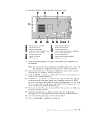
...the new system board in the rear of the computer chassis. Appendix A. Take note of the location of the power supply assembly to the system board. 1 Microprocessor heat sink 8 Diskette drive connector 2 Fan connectors (2) 9 Front panel connector 3 DIMM connectors (2) ...IDE and SATA 2 IDE hard 11 PATA Primary IDE connector (hard disk disk drive connectors (2) drive and CD-ROM drive) 5 PCI riser connector 12 Power connector (P2) 6 Speaker connector 13 Microprocessor heat sink clamps 7 POV connector 14 CD audio connector 9. Install the microprocessor on page 14. 11. ...
...the new system board in the rear of the computer chassis. Appendix A. Take note of the location of the power supply assembly to the system board. 1 Microprocessor heat sink 8 Diskette drive connector 2 Fan connectors (2) 9 Front panel connector 3 DIMM connectors (2) ...IDE and SATA 2 IDE hard 11 PATA Primary IDE connector (hard disk disk drive connectors (2) drive and CD-ROM drive) 5 PCI riser connector 12 Power connector (P2) 6 Speaker connector 13 Microprocessor heat sink clamps 7 POV connector 14 CD audio connector 9. Install the microprocessor on page 14. 11. ...

User Guide
Page 74
...lost or forgotten 24 setting, changing, deleting 26 user 26 PCI adapter 15 POST/BIOS 45 power Advanced Configuration and Power Interface (ACPI) support 3 Advanced Power Management support 3 features 3 power button and LED assembly replacement 41 power supply, removing and replacing 31 primary startup sequence 28 R recovering from a POST/BIOS update failure 46... 4, 14 removing and replacing 34 system management 2 U updating BIOS diskette 45 OS 45 updating POST/BIOS 45 user password 26 using IBM Setup Utility 25 IDE drive setup 27 passwords 26 security profile by device 27 V video subsystem 2
...lost or forgotten 24 setting, changing, deleting 26 user 26 PCI adapter 15 POST/BIOS 45 power Advanced Configuration and Power Interface (ACPI) support 3 Advanced Power Management support 3 features 3 power button and LED assembly replacement 41 power supply, removing and replacing 31 primary startup sequence 28 R recovering from a POST/BIOS update failure 46... 4, 14 removing and replacing 34 system management 2 U updating BIOS diskette 45 OS 45 updating POST/BIOS 45 user password 26 using IBM Setup Utility 25 IDE drive setup 27 passwords 26 security profile by device 27 V video subsystem 2

