
User Guide
Page 5
... POST/BIOS 45 Updating (flashing) BIOS from a diskette . . . . 45 Updating (flashing) BIOS from your computer 9 Obtaining device drivers 9 Opening the cover 10 Locating components 11 Accessing system board components and drives . . 12 Identifying parts on the system board . . . . . 13 Installing memory 14 Installing PCI adapters 15 Installing internal drives 16 Removing and replacing a CD-ROM, CD-RW, or DVD optical drive 18 Removing and replacing a hard disk drive . . . 19 Removing and replacing a diskette drive . . . 20 Connecting a serial ATA hard disk drive. . . . 20 Connecting an...
... POST/BIOS 45 Updating (flashing) BIOS from a diskette . . . . 45 Updating (flashing) BIOS from your computer 9 Obtaining device drivers 9 Opening the cover 10 Locating components 11 Accessing system board components and drives . . 12 Identifying parts on the system board . . . . . 13 Installing memory 14 Installing PCI adapters 15 Installing internal drives 16 Removing and replacing a CD-ROM, CD-RW, or DVD optical drive 18 Removing and replacing a hard disk drive . . . 19 Removing and replacing a diskette drive . . . 20 Connecting a serial ATA hard disk drive. . . . 20 Connecting an...

User Guide
Page 16
...™ processor v Internal cache (size varies by model type) Memory Support for a Video Graphics Array (VGA) monitor Audio subsystem The integrated AC'97 audio controller provides four audio connectors. Internal drives v 3.5-inch, half-inch (slim) diskette drive (some models) v Hard disk drive v CD-ROM, DVD-ROM, DVD-ROM/CD-RW Combo, CD-RW, or IBM Multi-Burner optical drive (some models) System management features v Remote Program Load (RPL) and Dynamic Host Configuration Protocol (DHCP) v Wake on LAN v Wake on page 25. For a listing of features for your specific model, go...
...™ processor v Internal cache (size varies by model type) Memory Support for a Video Graphics Array (VGA) monitor Audio subsystem The integrated AC'97 audio controller provides four audio connectors. Internal drives v 3.5-inch, half-inch (slim) diskette drive (some models) v Hard disk drive v CD-ROM, DVD-ROM, DVD-ROM/CD-RW Combo, CD-RW, or IBM Multi-Burner optical drive (some models) System management features v Remote Program Load (RPL) and Dynamic Host Configuration Protocol (DHCP) v Wake on LAN v Wake on page 25. For a listing of features for your specific model, go...
User Guide
Page 17
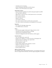
... height adapter slots v Two DIMM memory connectors Power v 200 Watt power supply with manual voltage selection switch v Automatic 50/60 Hz input frequency switching v Advanced Power Management support v Advanced Configuration and Power Interface (ACPI) support Security features v User and administrator passwords v Support for the addition of a cable lock such as a Kensington lock v Knockout holes for installing a rope clip (U-bolt) v Optional keylock on top cover v Startup sequence control v Startup without diskette drive, keyboard, or mouse v Diskette and hard disk I/O control v Serial and...
... height adapter slots v Two DIMM memory connectors Power v 200 Watt power supply with manual voltage selection switch v Automatic 50/60 Hz input frequency switching v Advanced Power Management support v Advanced Configuration and Power Interface (ACPI) support Security features v User and administrator passwords v Support for the addition of a cable lock such as a Kensington lock v Knockout holes for installing a rope clip (U-bolt) v Optional keylock on top cover v Startup sequence control v Startup without diskette drive, keyboard, or mouse v Diskette and hard disk I/O control v Serial and...

User Guide
Page 21
... these options as external speakers, a printer, or a scanner. v When possible, remove the option and install it . v Do not place the option on it directly in the computer without setting the option down. Handling static-sensitive devices Static electricity, although harmless to you are required for installing optional memory, PCI adapters, drives, and security features. Handle adapters and memory modules by the edges. For some external options, you . When adding an external option, use the...
... these options as external speakers, a printer, or a scanner. v When possible, remove the option and install it . v Do not place the option on it directly in the computer without setting the option down. Handling static-sensitive devices Static electricity, although harmless to you are required for installing optional memory, PCI adapters, drives, and security features. Handle adapters and memory modules by the edges. For some external options, you . When adding an external option, use the...

User Guide
Page 23
... PS/2 mouse connector Note: Some connectors on the World Wide Web. Locating connectors on the rear of your computer The following illustration shows locations of connectors on the rear of your computer. 1 Power cord connector 2 Cable lock latch 3 Rope clip (U-bolt) holes 4 PCI adapter slots 5 Serial connectors (2) 6 Ethernet connector 7 USB connectors (2) 8 VGA monitor connector 9 Parallel connector 10 Audio line-in README files with the device-driver files. Installation instructions are color-coded to help determine where to connect the cables. Chapter 2. Installing options...
... PS/2 mouse connector Note: Some connectors on the World Wide Web. Locating connectors on the rear of your computer The following illustration shows locations of connectors on the rear of your computer. 1 Power cord connector 2 Cable lock latch 3 Rope clip (U-bolt) holes 4 PCI adapter slots 5 Serial connectors (2) 6 Ethernet connector 7 USB connectors (2) 8 VGA monitor connector 9 Parallel connector 10 Audio line-in README files with the device-driver files. Installation instructions are color-coded to help determine where to connect the cables. Chapter 2. Installing options...
User Guide
Page 27
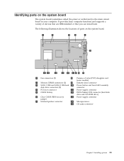
... and supports a variety of devices that are IBM-installed or that you can install later. Identifying parts on the system board. 1 Fan connectors (2) 8 Promise of value (POV) daughter card (some models) 2 Memory DIMM connectors (2) 9 Diskette drive connector 3 SATA 1 IDE and SATA 2 IDE hard 10 Power button and front LED assembly disk drive connectors (2) connector 4 PCI riser connector 11 Power supply connector 5 CMOS Battery 12 PATA Primary IDE connector (hard disk drive and CD-ROM drive) 6 Clear CMOS/BIOS recovery 13 Power supply connector jumper 7 Internal speaker connector...
... and supports a variety of devices that are IBM-installed or that you can install later. Identifying parts on the system board. 1 Fan connectors (2) 8 Promise of value (POV) daughter card (some models) 2 Memory DIMM connectors (2) 9 Diskette drive connector 3 SATA 1 IDE and SATA 2 IDE hard 10 Power button and front LED assembly disk drive connectors (2) connector 4 PCI riser connector 11 Power supply connector 5 CMOS Battery 12 PATA Primary IDE connector (hard disk drive and CD-ROM drive) 6 Clear CMOS/BIOS recovery 13 Power supply connector jumper 7 Internal speaker connector...

User Guide
Page 28
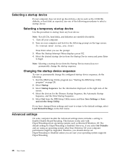
... PCI riser and adapters if it was removed. 6. See "Closing the cover and connecting the cables" on page 13. 3. Installing memory Your computer has two connectors for installing dual inline memory modules (DIMMs) that provide up to the original position. 7. Locate the DIMM connectors. See "Identifying parts on the system board" on page 24. 14 User Guide Make sure the notch in any combination. Replace the cover. See "Accessing system board components and drives...
... PCI riser and adapters if it was removed. 6. See "Closing the cover and connecting the cables" on page 13. 3. Installing memory Your computer has two connectors for installing dual inline memory modules (DIMMs) that provide up to the original position. 7. Locate the DIMM connectors. See "Identifying parts on the system board" on page 24. 14 User Guide Make sure the notch in any combination. Replace the cover. See "Accessing system board components and drives...

User Guide
Page 30
... PCI riser and adapters. 8. See "Closing the cover and connecting the cables" on page 24. Installing internal drives This section provides information and instructions for your computer uses to read other removable media drives When you install an internal drive, it is important to install additional drives but you are : v Parallel Advanced Technology Attachment (ATA) Integrated Drive Electronics (IDE) hard disk drive v Serial ATA IDE hard disk drive v Tape drives v CD-ROM, CD-RW, or DVD-ROM optical drives v Diskette and other types...
... PCI riser and adapters. 8. See "Closing the cover and connecting the cables" on page 24. Installing internal drives This section provides information and instructions for your computer uses to read other removable media drives When you install an internal drive, it is important to install additional drives but you are : v Parallel Advanced Technology Attachment (ATA) Integrated Drive Electronics (IDE) hard disk drive v Serial ATA IDE hard disk drive v Tape drives v CD-ROM, CD-RW, or DVD-ROM optical drives v Diskette and other types...

User Guide
Page 38
... then turn off the computer. 8. Install the PCI riser and adapters if removed. 5. Clear any removed parts, close the cover and connect cables to the standard position (pins 1 and 2). 10. If a cover lock is installed, you cannot close the cover. If your computer: 1. Reconnect the external cables and power cords to install any cables that the drive locks are left inside your computer" on page 12. 2. To update the configuration, see Chapter 3, "Using the IBM Setup Utility," on...
... then turn off the computer. 8. Install the PCI riser and adapters if removed. 5. Clear any removed parts, close the cover and connect cables to the standard position (pins 1 and 2). 10. If a cover lock is installed, you cannot close the cover. If your computer: 1. Reconnect the external cables and power cords to install any cables that the drive locks are left inside your computer" on page 12. 2. To update the configuration, see Chapter 3, "Using the IBM Setup Utility," on...

User Guide
Page 41
... IBM Setup Utility program menu, select Devices. 3. Select the desired devices and settings and press Enter. 5. Using the IBM Setup Utility 27 Start the IBM Setup Utility program (see "Starting the IBM Setup Utility program" on page 25). 2. Start the IBM Setup Utility program (see "Starting the IBM Setup Utility program" on page 25). 2. Then the serial ATA drive will operate in the system configuration. Select IDE Drives Setup. 4. Return to Disable, all diskettes are treated as hard disk drives or the CD-ROM drive) are disabled and will not be accessed...
... IBM Setup Utility program menu, select Devices. 3. Select the desired devices and settings and press Enter. 5. Using the IBM Setup Utility 27 Start the IBM Setup Utility program (see "Starting the IBM Setup Utility program" on page 25). 2. Start the IBM Setup Utility program (see "Starting the IBM Setup Utility program" on page 25). 2. Then the serial ATA drive will operate in the system configuration. Select IDE Drives Setup. 4. Return to Disable, all diskettes are treated as hard disk drives or the CD-ROM drive) are disabled and will not be accessed...
User Guide
Page 42
... operating system supports HyperThreading. 28 User Guide Select Startup Sequence. The default setting for the Primary Startup Sequence, the Automatic Startup Sequence, and the Error Startup Sequence. 5. Therefore, you see "Starting the IBM Setup Utility program" on page 25). 2. See the information displayed on the logo screen: (To interrupt normal startup, press Enter) Press Enter when you should always set HyperThreading to startup from any boot device. Advanced settings On some computer models the Advanced settings menu includes a setting...
... operating system supports HyperThreading. 28 User Guide Select Startup Sequence. The default setting for the Primary Startup Sequence, the Automatic Startup Sequence, and the Error Startup Sequence. 5. Therefore, you see "Starting the IBM Setup Utility program" on page 25). 2. See the information displayed on the logo screen: (To interrupt normal startup, press Enter) Press Enter when you should always set HyperThreading to startup from any boot device. Advanced settings On some computer models the Advanced settings menu includes a setting...
User Guide
Page 43
... User Guide and Hardware Maintenance manual (HMM) for your computer are provided to be serviced with customer replaceable units (CRU). See "Handling static-sensitive devices" on page 7. These procedures are available from the World Wide Web. Warning Hazardous moving parts in your computer after the power cord has been disconnected, the following CRUs: v power supply v microprocessor v system board v battery v speaker v fan v power button and LED assembly For memory DIMMs, PCI adapters, diskette drive...
... User Guide and Hardware Maintenance manual (HMM) for your computer are provided to be serviced with customer replaceable units (CRU). See "Handling static-sensitive devices" on page 7. These procedures are available from the World Wide Web. Warning Hazardous moving parts in your computer after the power cord has been disconnected, the following CRUs: v power supply v microprocessor v system board v battery v speaker v fan v power button and LED assembly For memory DIMMs, PCI adapters, diskette drive...

User Guide
Page 44
CRU list Battery, CMOS Bezel, front plastic Kit Cables, all Cover Cover lock assembly Diskette drive Fan assembly Floor stand Hard disk drives Hard disk drive bracket Keyboard Memory DIMMs Microprocessor Microprocessor heat sink Mouse Optical drives Phone line cord Power button and LED assembly Power supply, 200 Watt Riser card assembly RJ11 connector adapter Rotating drive bay assembly Shield, 5.25 EMC (DR9) Speaker assembly, internal Speakers, external Speaker power converter System board assembly V.90 Data/Fax Soft Modem Power supply model: API3PC24 Modem model: RD01-D270 30 User Guide
CRU list Battery, CMOS Bezel, front plastic Kit Cables, all Cover Cover lock assembly Diskette drive Fan assembly Floor stand Hard disk drives Hard disk drive bracket Keyboard Memory DIMMs Microprocessor Microprocessor heat sink Mouse Optical drives Phone line cord Power button and LED assembly Power supply, 200 Watt Riser card assembly RJ11 connector adapter Rotating drive bay assembly Shield, 5.25 EMC (DR9) Speaker assembly, internal Speakers, external Speaker power converter System board assembly V.90 Data/Fax Soft Modem Power supply model: API3PC24 Modem model: RD01-D270 30 User Guide
User Guide
Page 49
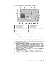
...slots in the rear of the power supply assembly to "Completing the installation" on the new system board in the front and is seated flush to the system board. 1 Microprocessor heat sink 8 Diskette drive connector 2 Fan connectors (2) 9 Front panel connector 3 DIMM connectors (2) 10 Power connector (P1) 4 SATA 1 IDE and SATA 2 IDE hard 11 PATA Primary IDE connector (hard disk disk drive connectors (2) drive and CD-ROM drive) 5 PCI riser connector 12 Power connector (P2) 6 Speaker connector 13 Microprocessor heat sink clamps 7 POV connector 14 CD audio connector 9. Install...
...slots in the rear of the power supply assembly to "Completing the installation" on the new system board in the front and is seated flush to the system board. 1 Microprocessor heat sink 8 Diskette drive connector 2 Fan connectors (2) 9 Front panel connector 3 DIMM connectors (2) 10 Power connector (P1) 4 SATA 1 IDE and SATA 2 IDE hard 11 PATA Primary IDE connector (hard disk disk drive connectors (2) drive and CD-ROM drive) 5 PCI riser connector 12 Power connector (P2) 6 Speaker connector 13 Microprocessor heat sink clamps 7 POV connector 14 CD audio connector 9. Install...

User Guide
Page 53
... screws that maintains the date, time, and settings for information about replacing and disposing of the battery. v If you turn on page 44. however, no charging or maintenance throughout its life; If the battery fails, the date, time, and configuration information (including passwords) are lost. An error message is displayed when you install or remove any component, read "Important safety information" on...
... screws that maintains the date, time, and settings for information about replacing and disposing of the battery. v If you turn on page 44. however, no charging or maintenance throughout its life; If the battery fails, the date, time, and configuration information (including passwords) are lost. An error message is displayed when you install or remove any component, read "Important safety information" on...

User Guide
Page 54
... computer. 2. Remove the speaker by sliding the it upward and out of the computer to the battery. 5. Use the IBM Setup Utility program to the speaker. 4. Note: Make sure you note the location of the cable that impede access to aide in removing the speaker. 7. Open the cover. 4. Note: You may need to slightly flex the side of the retaining bracket. Remove the PCI riser and PCI adapters that you work safely.
... computer. 2. Remove the speaker by sliding the it upward and out of the computer to the battery. 5. Use the IBM Setup Utility program to the speaker. 4. Note: Make sure you note the location of the cable that impede access to aide in removing the speaker. 7. Open the cover. 4. Note: You may need to slightly flex the side of the retaining bracket. Remove the PCI riser and PCI adapters that you work safely.

User Guide
Page 60
.... Reconnect the power cords for the computer and monitor to download, extract, and install the update. Remove any cables or adapters that impede access to pins 2 and 3. 7. Click the .txt file. 7. Carefully follow the printed instructions to electrical outlets. 10. See "Opening the cover" on the system board. Replace the Clear CMOS/BIOS Recovery jumper to the Clear CMOS/BIOS Recovery jumper. 5. Unplug all power cords from the operating system. See "Closing the cover and connecting the cables" on page...
.... Reconnect the power cords for the computer and monitor to download, extract, and install the update. Remove any cables or adapters that impede access to pins 2 and 3. 7. Click the .txt file. 7. Carefully follow the printed instructions to electrical outlets. 10. See "Opening the cover" on the system board. Replace the Clear CMOS/BIOS Recovery jumper to the Clear CMOS/BIOS Recovery jumper. 5. Unplug all power cords from the operating system. See "Closing the cover and connecting the cables" on page...
User Guide
Page 66
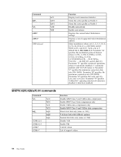
... Profile 1 Disable auto-retrain Enable auto-retrain Displays the current Select Modulation settings Displays a list of support values 52 User Guide Parameter "e" specifies the codec type (0= Law, and 1=A-Law). d=30056000; b=0-1; and f=0-1. A, b, c, d, e, f default=12, 1, 300, 56000, 0, 0. c=300-56000; Parameter "b" specifies automode operations where: 0=automode disabled, 1= automode enabled with fallback options Normal data link only (same as \N0) Disable V.44 Enable V.44 Current values List of supported Select Modulation options Select modulation...
... Profile 1 Disable auto-retrain Enable auto-retrain Displays the current Select Modulation settings Displays a list of support values 52 User Guide Parameter "e" specifies the codec type (0= Law, and 1=A-Law). d=30056000; b=0-1; and f=0-1. A, b, c, d, e, f default=12, 1, 300, 56000, 0, 0. c=300-56000; Parameter "b" specifies automode operations where: 0=automode disabled, 1= automode enabled with fallback options Normal data link only (same as \N0) Disable V.44 Enable V.44 Current values List of supported Select Modulation options Select modulation...
User Guide
Page 73
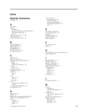
Index Special characters .iso image 45 A Access IBM 1 adapter installing 15 peripheral component interconnect (PCI) 4 removing and replacing 15 slots 15 administrator password 25, 26 audio subsystem 2 automatic startup sequence 28 B battery, changing 39 bezel replacement 42 BIOS settings 25 BIOS updating 45 Boot-block recovery 46 bootable CD image 45 C cable lock 21 cables, connecting 24 CD drive, removing and replacing 18 changing battery 39 startup device sequence 28 cleaning mouse 47 closing the cover 24 components, internal 11, 12 connectors front 8 rear 9 cover closing 24 lock 21...
Index Special characters .iso image 45 A Access IBM 1 adapter installing 15 peripheral component interconnect (PCI) 4 removing and replacing 15 slots 15 administrator password 25, 26 audio subsystem 2 automatic startup sequence 28 B battery, changing 39 bezel replacement 42 BIOS settings 25 BIOS updating 45 Boot-block recovery 46 bootable CD image 45 C cable lock 21 cables, connecting 24 CD drive, removing and replacing 18 changing battery 39 startup device sequence 28 cleaning mouse 47 closing the cover 24 components, internal 11, 12 connectors front 8 rear 9 cover closing 24 lock 21...

User Guide
Page 74
.../BIOS update failure 46 removing and replacing adapters 15 battery 39 bezel 42 diskette drive 20 fan 42 hard disk drive 19 memory 14 microprocessor 36 optical drive 18 power button and LED assembly 41 power supply assembly 31 speaker 40 system board assembly 34 removing drives 12 riser card 15 S security cable lock 21 features 3 profile by device 27 60 User Guide selecting startup device 28 temporary startup device 28 serial ATA drive 16, 17 serial ATA hard disk drive, connecting 20 software 3 speaker replacement 40 specifications 5 starting setup utility 25 startup sequence 28 system board...
.../BIOS update failure 46 removing and replacing adapters 15 battery 39 bezel 42 diskette drive 20 fan 42 hard disk drive 19 memory 14 microprocessor 36 optical drive 18 power button and LED assembly 41 power supply assembly 31 speaker 40 system board assembly 34 removing drives 12 riser card 15 S security cable lock 21 features 3 profile by device 27 60 User Guide selecting startup device 28 temporary startup device 28 serial ATA drive 16, 17 serial ATA hard disk drive, connecting 20 software 3 speaker replacement 40 specifications 5 starting setup utility 25 startup sequence 28 system board...


