Service Guide
Page 6
... 30 Using the Service Diskette (for the 5x3 models 30 Using the IBM Diagnostics for Peripherals (for the 5x3 models 31 Using the IBM Diagnostics for POS System Units and Peripherals (for the SurePOS 500 Models 5x3 and 544/564 33 Handling static-sensitive devices 34 Covers -...- removing and replacing 53 Calibrating the presence sensor (Models 563, 564, 573, and 5A3 only) . . . 54 Speaker - removing and replacing 55 Power supply - removing and replacing 58 Connecting the cables and using cable-ties for countertop and cash drawer . . . . 91 removing and replacing 62 Cooling duct ...
... 30 Using the Service Diskette (for the 5x3 models 30 Using the IBM Diagnostics for Peripherals (for the 5x3 models 31 Using the IBM Diagnostics for POS System Units and Peripherals (for the SurePOS 500 Models 5x3 and 544/564 33 Handling static-sensitive devices 34 Covers -...- removing and replacing 53 Calibrating the presence sensor (Models 563, 564, 573, and 5A3 only) . . . 54 Speaker - removing and replacing 55 Power supply - removing and replacing 58 Connecting the cables and using cable-ties for countertop and cash drawer . . . . 91 removing and replacing 62 Cooling duct ...
Service Guide
Page 9
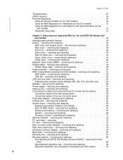
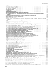
... replacement 51 32. Cable routing 61 42. Cooling duct 64 45. Removing the PC card adapter slot blank 74 52. Countertop mounting option with integration tray 7 4. Serial number location: A 16 11. Power supply remove/replace 58...foot option 12 9. Power supply remove/replace 57 38. Example of the Advanced BIOS Features window 20 14. Side panel door location 43 24. Memory module removal 73 51. SurePOS 500 Models 5x3 and 544/... a PC card adapter 75 © Copyright IBM Corp. 2004, 2006 vii CMOS reset jumper JP7 23 16. August 3, 2006 Figures 1.
... replacement 51 32. Cable routing 61 42. Cooling duct 64 45. Removing the PC card adapter slot blank 74 52. Countertop mounting option with integration tray 7 4. Serial number location: A 16 11. Power supply remove/replace 58...foot option 12 9. Power supply remove/replace 57 38. Example of the Advanced BIOS Features window 20 14. Side panel door location 43 24. Memory module removal 73 51. SurePOS 500 Models 5x3 and 544/... a PC card adapter 75 © Copyright IBM Corp. 2004, 2006 vii CMOS reset jumper JP7 23 16. August 3, 2006 Figures 1.
Service Guide
Page 10
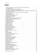
...the base foot from cash drawer integration tray 90 67. Removing rear modesty cover and distributed customer display 89 66. Detaching system from the SurePOS 500 Models 5x3 and 544/564 85 62. Removing the 4610 printer from a keyboard integration tray 102 79. Removing the 4820 SurePoint Solution display ... 122 99. Removing the keyboard integration tray attached to the printer 123 100. Removing the coin-roll cutter 112 89. Removing the SurePOS 500 Models 5x3 and 544/564 from the slide assembly 108 84. Attaching and routing the signal and power supply cables to a cash drawer 104 81.
...the base foot from cash drawer integration tray 90 67. Removing rear modesty cover and distributed customer display 89 66. Detaching system from the SurePOS 500 Models 5x3 and 544/564 85 62. Removing the 4610 printer from a keyboard integration tray 102 79. Removing the 4820 SurePoint Solution display ... 122 99. Removing the keyboard integration tray attached to the printer 123 100. Removing the coin-roll cutter 112 89. Removing the SurePOS 500 Models 5x3 and 544/564 from the slide assembly 108 84. Attaching and routing the signal and power supply cables to a cash drawer 104 81.
Service Guide
Page 13
... IBM Corp. 2004, 2006 xi PS/2 keyboard/mouse port assignment 15 5. Repair actions for 9-pin serial connector 181 29. RJ-45 connector-pin assignments 181 30. Assignment of diskette-drive connector pins 184 33. Assignment of cash drawer connector pins 186 36. SurePOS 500 Models...assignments 179 22. Assignments for 15-pin serial connector 183 31. Assignment of parallel-connector pins 183 32. Power consumption 178 21. Using the touch screen 17 6. Default serial-port assignments 15 3. Power cords 167 14. SurePOS 500 Series power supply 178 20.
... IBM Corp. 2004, 2006 xi PS/2 keyboard/mouse port assignment 15 5. Repair actions for 9-pin serial connector 181 29. RJ-45 connector-pin assignments 181 30. Assignment of diskette-drive connector pins 184 33. Assignment of cash drawer connector pins 186 36. SurePOS 500 Models...assignments 179 22. Assignments for 15-pin serial connector 183 31. Assignment of parallel-connector pins 183 32. Power consumption 178 21. Using the touch screen 17 6. Default serial-port assignments 15 3. Power cords 167 14. SurePOS 500 Series power supply 178 20.
Service Guide
Page 29
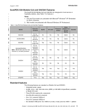
... Models 5x3 and 544/564: v Integrated power supply v 40-GB, 3.5-in., IDE, hard disk drive (HDD) (or 256 MB CompactFlash, available in . Ex3 and Ex4 models are preloaded with Microsoft Windows XP Professional. | Table 1. Introducing the IBM SurePOS 500 Series Models 533, 543, 544, 553,... 563, 564, 573, and 5A3 3 SurePOS 500 Models 5x3 and 544/564 Features | ||| ...
... Models 5x3 and 544/564: v Integrated power supply v 40-GB, 3.5-in., IDE, hard disk drive (HDD) (or 256 MB CompactFlash, available in . Ex3 and Ex4 models are preloaded with Microsoft Windows XP Professional. | Table 1. Introducing the IBM SurePOS 500 Series Models 533, 543, 544, 553,... 563, 564, 573, and 5A3 3 SurePOS 500 Models 5x3 and 544/564 Features | ||| ...

Service Guide
Page 53
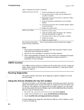
...may cause binds, such as pens or paper clips. Ensure that may cause unpredictable problems. Before exchanging the system board in . 3. Replace the power supply. removing and replacing" on page 65. Replace the display tablet. Cash drawer does not open when cash drawer key is turned to "Running | Diagnostics...the system unit is plugged into the system board connectors P1 and P2. 4. Resolving problems 27 August 3, 2006 Troubleshooting Troubleshooting If the SurePOS 500 Models 5x3 and 544/564 system fails and there is no error message or beep code, see if corrupted CMOS is the source ...
...may cause binds, such as pens or paper clips. Ensure that may cause unpredictable problems. Before exchanging the system board in . 3. Replace the power supply. removing and replacing" on page 65. Replace the display tablet. Cash drawer does not open when cash drawer key is turned to "Running | Diagnostics...the system unit is plugged into the system board connectors P1 and P2. 4. Resolving problems 27 August 3, 2006 Troubleshooting Troubleshooting If the SurePOS 500 Models 5x3 and 544/564 system fails and there is no error message or beep code, see if corrupted CMOS is the source ...
Service Guide
Page 56
...power supplies. Symptoms and actions (continued) Diskette drive does not work. 1. Replace the system board. It provides menu-driven tests and | utilities that the correct boot device is not shipped with a bootable diskette, replace the drive and cable. 6. Check the diskette drive cable connections. 2. Select SurePOS 500...-xx3 Diagnostic/Service Diskette. | To build diskettes from the IBM Retail Store Solutions | Web site using application programs, you may receive error messages ...
...power supplies. Symptoms and actions (continued) Diskette drive does not work. 1. Replace the system board. It provides menu-driven tests and | utilities that the correct boot device is not shipped with a bootable diskette, replace the drive and cable. 6. Check the diskette drive cable connections. 2. Select SurePOS 500...-xx3 Diagnostic/Service Diskette. | To build diskettes from the IBM Retail Store Solutions | Web site using application programs, you may receive error messages ...
Service Guide
Page 59
... removing and replacing 52 LED card and cable - removing and replacing 55 Power supply - removing and replacing 58 Connecting the cables and using cable-ties for countertop and cash drawer 91 © Copyright IBM Corp. 2004, 2006 33 removing and replacing 67 Fansink - removing and ... Cooling duct - removing and replacing 36 HDD cover clips - removing and replacing 37 Rear cover - Removing and replacing FRUs for the SurePOS 500 Models 5x3 and 544/564 Handling static-sensitive devices 34 Covers - removing and replacing 57 Cable tie bar - removing and replacing 64 ...
... removing and replacing 52 LED card and cable - removing and replacing 55 Power supply - removing and replacing 58 Connecting the cables and using cable-ties for countertop and cash drawer 91 © Copyright IBM Corp. 2004, 2006 33 removing and replacing 67 Fansink - removing and ... Cooling duct - removing and replacing 36 HDD cover clips - removing and replacing 37 Rear cover - Removing and replacing FRUs for the SurePOS 500 Models 5x3 and 544/564 Handling static-sensitive devices 34 Covers - removing and replacing 57 Cable tie bar - removing and replacing 64 ...

Service Guide
Page 75
...the speaker, if present. removing and replacing" on page 48. 3. Remove the power supply as described at "HDD cover and speaker panel - To replace, reverse this procedure. Removing and replacing FRUs for the SurePOS 500 Models 5x3 and 544/564 49 Disconnect the cable from the plastic guide in the...6. Pull the cable free from the bottom rear of the tablet. 4. Switch OFF the power to the SurePOS 500 Models 5x3 and 544/564. Remove the rear cover as described at "Power supply - Unplug the power cord from the system board. 11. Disconnect the cable clamps behind the LED card and ...
...the speaker, if present. removing and replacing" on page 48. 3. Remove the power supply as described at "HDD cover and speaker panel - To replace, reverse this procedure. Removing and replacing FRUs for the SurePOS 500 Models 5x3 and 544/564 49 Disconnect the cable from the plastic guide in the...6. Pull the cable free from the bottom rear of the tablet. 4. Switch OFF the power to the SurePOS 500 Models 5x3 and 544/564. Remove the rear cover as described at "Power supply - Unplug the power cord from the system board. 11. Disconnect the cable clamps behind the LED card and ...

Service Guide
Page 78
... board - Disconnect the power cable from the power supply and the data cable from the external power source. To replace, reverse this procedure. 52 HDD cables - removing and replacing" on page 51. 2. See "Base plate - It is not required that you must remove the system board. Switch OFF the power to the SurePOS 500 Models 5x3 and...
... board - Disconnect the power cable from the power supply and the data cable from the external power source. To replace, reverse this procedure. 52 HDD cables - removing and replacing" on page 51. 2. See "Base plate - It is not required that you must remove the system board. Switch OFF the power to the SurePOS 500 Models 5x3 and...

Service Guide
Page 79
... - Remove the back cover as described at "Power supply - See "Calibrating the presence sensor (Models 563, 564, 573, and 5A3 only)" on page 57. Removing and replacing FRUs for the SurePOS 500 Models 5x3 and 544/564 53 b. Unplug the power cord from the LED card (see Figure 32) and remove it out from the LED...
... - Remove the back cover as described at "Power supply - See "Calibrating the presence sensor (Models 563, 564, 573, and 5A3 only)" on page 57. Removing and replacing FRUs for the SurePOS 500 Models 5x3 and 544/564 53 b. Unplug the power cord from the LED card (see Figure 32) and remove it out from the LED...

Service Guide
Page 83
... screws at "Rear cover - Power supply remove/replace To replace the power supply, reverse this procedure. removing and replacing" on page 58. 4. This is connected to the SurePOS 500 Models 5x3 and 544/564. Unplug the AC power cord on the back of power supply keep the fan running when the... system is normal operation. 1. Slide the bottom of the power supply, as described at "Cable tie bar - Chapter 4. August 3, 2006 Power supply Power supply - Remove ...
... screws at "Rear cover - Power supply remove/replace To replace the power supply, reverse this procedure. removing and replacing" on page 58. 4. This is connected to the SurePOS 500 Models 5x3 and 544/564. Unplug the AC power cord on the back of power supply keep the fan running when the... system is normal operation. 1. Slide the bottom of the power supply, as described at "Cable tie bar - Chapter 4. August 3, 2006 Power supply Power supply - Remove ...

Service Guide
Page 84
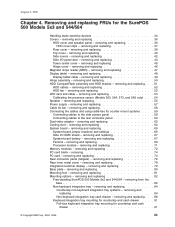
Cable tie bar August 3, 2006 Cable tie bar - removing and replacing 1. To replace the cable tie bar, reverse this procedure. A B Figure 38. Unplug the power cord from the tie bar by cutting the cable ties. Disconnect all cables from the external power source. 3. removing and replacing" on page 38. 4. Remove the screw A and thumbscrew B , as shown at "Rear cover - Power supply remove/replace 58 Switch OFF the power to the SurePOS 500 Models 5x3 and 544/564. 2. Remove the rear cover as shown in Figure 38. 5.
Cable tie bar August 3, 2006 Cable tie bar - removing and replacing 1. To replace the cable tie bar, reverse this procedure. A B Figure 38. Unplug the power cord from the tie bar by cutting the cable ties. Disconnect all cables from the external power source. 3. removing and replacing" on page 38. 4. Remove the screw A and thumbscrew B , as shown at "Rear cover - Power supply remove/replace 58 Switch OFF the power to the SurePOS 500 Models 5x3 and 544/564. 2. Remove the rear cover as shown in Figure 38. 5.

Service Guide
Page 87
...cable tie bar with tie-warps if desired. Cable routing 1. See Figure 41 for cleaning and servicing. Switch OFF the power at the system. Secure the cables to the power supply. 3. Attention: the rear cover will not close properly if signal cables are no jagged edges sticking out. Signal cables ...must be routed to the left of the tie-wraps flush so there are routed to the right of the AC power cable, as shown in Figure 41. 4. August 3, 2006 Cable connections B A Figure 41. Chapter 4. Removing and replacing FRUs for the SurePOS 500 Models 5x3 and 544/564 61
...cable tie bar with tie-warps if desired. Cable routing 1. See Figure 41 for cleaning and servicing. Switch OFF the power at the system. Secure the cables to the power supply. 3. Attention: the rear cover will not close properly if signal cables are no jagged edges sticking out. Signal cables ...must be routed to the left of the tie-wraps flush so there are routed to the right of the AC power cable, as shown in Figure 41. 4. August 3, 2006 Cable connections B A Figure 41. Chapter 4. Removing and replacing FRUs for the SurePOS 500 Models 5x3 and 544/564 61

Service Guide
Page 88
...2006 Dual-video adapter - Unplug the power cord from the external power source. 2. Remove the power supply. Attention: The dual-video adapter is optional on all models of 4840. If no dual video adapter is installed, remove jumpers JP29 through JP35 to the SurePOS 500 Models 5x3 and 544/564. Video ...card removal 5. See "Power supply - Remove the four screws shown in Figure 42 and remove...
...2006 Dual-video adapter - Unplug the power cord from the external power source. 2. Remove the power supply. Attention: The dual-video adapter is optional on all models of 4840. If no dual video adapter is installed, remove jumpers JP29 through JP35 to the SurePOS 500 Models 5x3 and 544/564. Video ...card removal 5. See "Power supply - Remove the four screws shown in Figure 42 and remove...

Service Guide
Page 90
... page 57. 5. Switch OFF the power to the SurePOS 500 Models 5x3 and 544/564. Remove the back cover as shown in Figure 44.. Remove rear inner metal cover. See "Rear inner metal cover - Remove the power supply. See "Power supply - See "Rear connector panel (tailgate) - Unplug the power cord from the external power source. 2. Cooling duct To replace...
... page 57. 5. Switch OFF the power to the SurePOS 500 Models 5x3 and 544/564. Remove the back cover as shown in Figure 44.. Remove rear inner metal cover. See "Rear inner metal cover - Remove the power supply. See "Power supply - See "Rear connector panel (tailgate) - Unplug the power cord from the external power source. 2. Cooling duct To replace...
Service Guide
Page 91
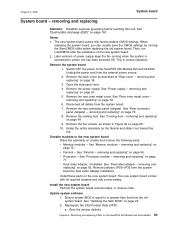
Then, run LoadCMOS after the installation of power supply keep the fan running the SaveCMOS utility before touching this unit. This is connected to or greater than that from the system board for the SurePOS 500 Models 5x3 and 544/564 65 Open the side panel door. 4. Grasp ...a. Removing and replacing FRUs for dual video adapter installation. Remove the system board 1. Switch OFF the power to the new system board Place the assembly on page 66. 10. Transfer modules to the SurePOS 500 Models 5x3 and 544/564. v Fansink - See "Fansink - See "Dual-video adapter - See ...
Then, run LoadCMOS after the installation of power supply keep the fan running the SaveCMOS utility before touching this unit. This is connected to or greater than that from the system board for the SurePOS 500 Models 5x3 and 544/564 65 Open the side panel door. 4. Grasp ...a. Removing and replacing FRUs for dual video adapter installation. Remove the system board 1. Switch OFF the power to the new system board Place the assembly on page 66. 10. Transfer modules to the SurePOS 500 Models 5x3 and 544/564. v Fansink - See "Fansink - See "Dual-video adapter - See ...

Service Guide
Page 93
...the system board, the jumper must remain on the system board for the SurePOS 500 Models 5x3 and 544/564 67 Remove the back cover as described at all jumpers by a small white circle. See "Power supply - removing and replacing" on page 36. 3. Removing and replacing FRUs... for easy identification. to the SurePOS 500 Models 5x3 and 544/564. removing and replacing" on page 78. 4. Remove the power supply. Note: Pin 1 is attached to the system board....
...the system board, the jumper must remain on the system board for the SurePOS 500 Models 5x3 and 544/564 67 Remove the back cover as described at all jumpers by a small white circle. See "Power supply - removing and replacing" on page 36. 3. Removing and replacing FRUs... for easy identification. to the SurePOS 500 Models 5x3 and 544/564. removing and replacing" on page 78. 4. Remove the power supply. Note: Pin 1 is attached to the system board....

Service Guide
Page 102
...power supply. Unplug the power cord from the tailgate. Pull the connector panel out and disconnect the power cable from the external power source. 2. Make sure the two connectors on the back of the tailgate line up with the connectors on page 78. 5. Switch OFF the power to reassemble. Reverse the steps to the SurePOS 500... Models 5x3 and 544/564. A Figure 53. removing and replacing" on page 36 and unplug the power cord from the tailgate connector. Disconnect all cables ...
...power supply. Unplug the power cord from the tailgate. Pull the connector panel out and disconnect the power cable from the external power source. 2. Make sure the two connectors on the back of the tailgate line up with the connectors on page 78. 5. Switch OFF the power to reassemble. Reverse the steps to the SurePOS 500... Models 5x3 and 544/564. A Figure 53. removing and replacing" on page 36 and unplug the power cord from the tailgate connector. Disconnect all cables ...
Service Guide
Page 115
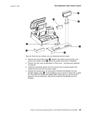
... in Figure 66 on page 38. 6. Removing and replacing FRUs for the SurePOS 500 Models 5x3 and 544/564 89 Remove the thumbscrews (2) securing the SurePOS 500 Models 5x3 and 544/564 adapter plate A to free the plate from the power supply. 7. Remove the SurePOS 500 Models 5x3 and 544/564. Chapter 4. removing and replacing" on page 90...
... in Figure 66 on page 38. 6. Removing and replacing FRUs for the SurePOS 500 Models 5x3 and 544/564 89 Remove the thumbscrews (2) securing the SurePOS 500 Models 5x3 and 544/564 adapter plate A to free the plate from the power supply. 7. Remove the SurePOS 500 Models 5x3 and 544/564. Chapter 4. removing and replacing" on page 90...

