
Owner's Manual
Page 1
... 1-800-468-1502. Mount Thermostat Wallplate...7 Step 4. Set the Clock ...13 Step 10. All Rights Reserved 69-1199-4 Honeywell CT3500/CT3595 PROGRAMMABLE THERMOSTAT Weekday, Saturday and Sunday Programmable Heat and/or Cool Low Voltage (20 to 30 Vac) Thermostat and Wallplate Model CT3500/CT3595 OWNER'S GUIDE Para pedir estas instrucciones en español, llame al 1-800-468-1502. Install the Batteries ...9 Step 6. Operating Your Thermostat...17 Step 12. Table of...
... 1-800-468-1502. Mount Thermostat Wallplate...7 Step 4. Set the Clock ...13 Step 10. All Rights Reserved 69-1199-4 Honeywell CT3500/CT3595 PROGRAMMABLE THERMOSTAT Weekday, Saturday and Sunday Programmable Heat and/or Cool Low Voltage (20 to 30 Vac) Thermostat and Wallplate Model CT3500/CT3595 OWNER'S GUIDE Para pedir estas instrucciones en español, llame al 1-800-468-1502. Install the Batteries ...9 Step 6. Operating Your Thermostat...17 Step 12. Table of...
Owner's Manual
Page 2
... Honeywell thermostat - Read these instructions can use the preprogrammed schedule, or set your old control in comfort and convenience. It comes preprogrammed. This manual answers many of the questions that can arise as you leave home or go on to follow these instructions carefully. Total comfort temperature management with your new Honeywell thermostat the smart thermostat that; • Keeps you comfortable by automatically calculating exactly when the furnace or air...
... Honeywell thermostat - Read these instructions can use the preprogrammed schedule, or set your old control in comfort and convenience. It comes preprogrammed. This manual answers many of the questions that can arise as you leave home or go on to follow these instructions carefully. Total comfort temperature management with your new Honeywell thermostat the smart thermostat that; • Keeps you comfortable by automatically calculating exactly when the furnace or air...
Owner's Manual
Page 3
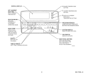
DIGITAL DISPLAY SET CURRENT DAY/TIME SETS CURRENT TIME AND DAY RUN PROGRAM RETURNS THERMOSTAT TO NORMAL OPERATING MODE Run Program Set Current Day/Time HOLD TEMP SETS A HOLD TEMPERATURE AND ACTIVATES VACATION HOLD FEATURE. Hold Temp Day DAY SETS DAY OF THE WEEK TIME /TIME SETS TIME FORWARD OR BACK Time Wake Heat/Cool Settings Set Program Leave Return Sleep Heat Off Cool System On Fan Auto RAISES TEMPERATURE SETTING LOWERS TEMPERATURE SETTING DISPLAYS CURRENT HEAT/COOL TEMPERATURE SETTING PROGRAM PERIODS WAKE/LEAVE/RETURN/SLEEP: ENTERS PROGRAMMING MODE SYSTEM SWITCH SELECTS ...
DIGITAL DISPLAY SET CURRENT DAY/TIME SETS CURRENT TIME AND DAY RUN PROGRAM RETURNS THERMOSTAT TO NORMAL OPERATING MODE Run Program Set Current Day/Time HOLD TEMP SETS A HOLD TEMPERATURE AND ACTIVATES VACATION HOLD FEATURE. Hold Temp Day DAY SETS DAY OF THE WEEK TIME /TIME SETS TIME FORWARD OR BACK Time Wake Heat/Cool Settings Set Program Leave Return Sleep Heat Off Cool System On Fan Auto RAISES TEMPERATURE SETTING LOWERS TEMPERATURE SETTING DISPLAYS CURRENT HEAT/COOL TEMPERATURE SETTING PROGRAM PERIODS WAKE/LEAVE/RETURN/SLEEP: ENTERS PROGRAMMING MODE SYSTEM SWITCH SELECTS ...
Owner's Manual
Page 4
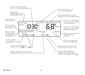
... PROGRAMMED SHOWS CURRENT PROGRAM PERIOD OR PERIOD BEING PROGRAMMED Set Program Set Day/Time Temporary Setting Hold for Em Ht AM Aux Ht Room Humid MonTueWedThuFriSatSun Days WakeLeaveReturnSleep In Recovery Filter System Em Heat Off Cool Auto Wait Outdoor Repl Batt SHOWS THE TEMPERATURE DISPLAYED IS THE CURRENT SET TEMPERATURE SHOWS THE TEMPERATURE DISPLAYED IS THE CURRENT ROOM TEMPERATURE SHOWS THE BATTERIES ARE LOW AND MUST BE REPLACED SHOWS CURRENT SYSTEM SWITCH POSITION HEAT/OFF/COOL DISPLAYS EITHER ROOM OR SET TEMPERATURES SHOWS THAT THERMOSTAT...
... PROGRAMMED SHOWS CURRENT PROGRAM PERIOD OR PERIOD BEING PROGRAMMED Set Program Set Day/Time Temporary Setting Hold for Em Ht AM Aux Ht Room Humid MonTueWedThuFriSatSun Days WakeLeaveReturnSleep In Recovery Filter System Em Heat Off Cool Auto Wait Outdoor Repl Batt SHOWS THE TEMPERATURE DISPLAYED IS THE CURRENT SET TEMPERATURE SHOWS THE TEMPERATURE DISPLAYED IS THE CURRENT ROOM TEMPERATURE SHOWS THE BATTERIES ARE LOW AND MUST BE REPLACED SHOWS CURRENT SYSTEM SWITCH POSITION HEAT/OFF/COOL DISPLAYS EITHER ROOM OR SET TEMPERATURES SHOWS THAT THERMOSTAT...
Owner's Manual
Page 5
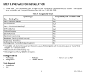
If your system. Electronic Ignition Yes Gas-fired Boilers Yesa Gas - 750 Millivolt Heat Onlyb Yes Oil-Fired Boilers Yesa Oil-Fired Furnace Yes Electric Furnace Yes Electric Air Conditioning Yes Baseboard Electric (120/240 line volt)c No Single Stage Heat Pump Yes Multistage Heat Pumps/Multistage Equipment No a Compatible with 3-wire zone valves or 2-wire White Rodgers no. 1361 zone valves. Not compatible with 2-wire Honeywell and Taco zone...
If your system. Electronic Ignition Yes Gas-fired Boilers Yesa Gas - 750 Millivolt Heat Onlyb Yes Oil-Fired Boilers Yesa Oil-Fired Furnace Yes Electric Furnace Yes Electric Air Conditioning Yes Baseboard Electric (120/240 line volt)c No Single Stage Heat Pump Yes Multistage Heat Pumps/Multistage Equipment No a Compatible with 3-wire zone valves or 2-wire White Rodgers no. 1361 zone valves. Not compatible with 2-wire Honeywell and Taco zone...
Owner's Manual
Page 6
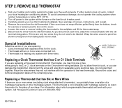
... using electrical tape. Record the colors and terminal designation labels of the new thermostat. q Remove the cover from the old thermostat. q Disconnect the wires from the old thermostat. STEP 2. REMOVE OLD THERMOSTAT q Test your system, call Honeywell Customer Care at the furnace or the fuse/circuit breaker panel. q Carefully unpack your local heating/air-conditioning dealer. Save package of a multistage heat pump or other multistage system. q Loosen the screw or screws holding...
... using electrical tape. Record the colors and terminal designation labels of the new thermostat. q Remove the cover from the old thermostat. q Disconnect the wires from the old thermostat. STEP 2. REMOVE OLD THERMOSTAT q Test your system, call Honeywell Customer Care at the furnace or the fuse/circuit breaker panel. q Carefully unpack your local heating/air-conditioning dealer. Save package of a multistage heat pump or other multistage system. q Loosen the screw or screws holding...
Owner's Manual
Page 7
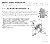
... wallplate over the holes. Thermostat functions properly when WALL ANCHORS (2) not level. q Tighten mounting screws. Replacing a Thermostat that best fit the application. See illustration at right. Your thermostat will work only if you have three wires. M16427 q Remove the wallplate from the thermostat. Level the wallplate for a heating only system and can operate the fan using the fan ON switch this thermostat works with the wall. However, some hot...
... wallplate over the holes. Thermostat functions properly when WALL ANCHORS (2) not level. q Tighten mounting screws. Replacing a Thermostat that best fit the application. See illustration at right. Your thermostat will work only if you have three wires. M16427 q Remove the wallplate from the thermostat. Level the wallplate for a heating only system and can operate the fan using the fan ON switch this thermostat works with the wall. However, some hot...
Owner's Manual
Page 8
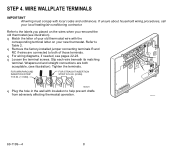
... affecting thermostat operation. R q Loosen the terminal screws. M4826 q Plug the hole in the wall with local codes and ordinances. Refer to both acceptable, (see illustration). q For wiring diagrams, if needed, see illustration). Slip each wire beneath its matching W Y G terminal. M16425 69-1199-4 8 WIRE WALLPLATE TERMINALS IMPORTANT All wiring must comply with insulation to Table 2. q Remove the factory-installed jumper connecting terminals R and RC if wires are both of your old thermostat wire with...
... affecting thermostat operation. R q Loosen the terminal screws. M4826 q Plug the hole in the wall with local codes and ordinances. Refer to both acceptable, (see illustration). q For wiring diagrams, if needed, see illustration). Slip each wire beneath its matching W Y G terminal. M16425 69-1199-4 8 WIRE WALLPLATE TERMINALS IMPORTANT All wiring must comply with insulation to Table 2. q Remove the factory-installed jumper connecting terminals R and RC if wires are both of your old thermostat wire with...
Owner's Manual
Page 9
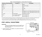
... the wire with electrical tape and push the taped wire back into the wiring hole in heat. (Single stage heat pump only). WALLPLATE B R RC O W Y G INSTALL 3 AA ALKALINE BATTERIES AS SHOWN, POSITIVE (+) TERMINALS TOWARD TOP. M10622 9 69-1199-4 Table 2. Terminal Designations on existing thermostat, remove jumper and connect Rh to R and R to Rc. Second stage cool. c Tape off B. INSTALL THE BATTERIES IMPORTANT Three fresh AA alkaline batteries must be installed for cooling W, W1, H W Heat Y, Y1, M Y Cooling G, F G Fan...
... the wire with electrical tape and push the taped wire back into the wiring hole in heat. (Single stage heat pump only). WALLPLATE B R RC O W Y G INSTALL 3 AA ALKALINE BATTERIES AS SHOWN, POSITIVE (+) TERMINALS TOWARD TOP. M10622 9 69-1199-4 Table 2. Terminal Designations on existing thermostat, remove jumper and connect Rh to R and R to Rc. Second stage cool. c Tape off B. INSTALL THE BATTERIES IMPORTANT Three fresh AA alkaline batteries must be installed for cooling W, W1, H W Heat Y, Y1, M Y Cooling G, F G Fan...
Owner's Manual
Page 10
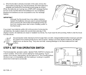
As a precaution when leaving home for one to lack of power. SET FAN OPERATION SWITCH The thermostat fan operation switch, labeled FUEL SWITCH is factory set the switch to turn on the wall, remove the thermostat by placing your system is an electric heat system, set in the F position. Replace the batteries as soon as long. If the display is blank, the batteries are running low, a REPL BAT message flashes for longer than a month, change batteries before leaving to prevent 60 70 80...
As a precaution when leaving home for one to lack of power. SET FAN OPERATION SWITCH The thermostat fan operation switch, labeled FUEL SWITCH is factory set the switch to turn on the wall, remove the thermostat by placing your system is an electric heat system, set in the F position. Replace the batteries as soon as long. If the display is blank, the batteries are running low, a REPL BAT message flashes for longer than a month, change batteries before leaving to prevent 60 70 80...
Owner's Manual
Page 13
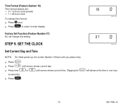
... Factory Set Function (Feature Number 37) Do not change time format: q Press once. STEP 9. q Press . Time Format (Feature Number 16) Time format options are: - 0 = 12-hour clock (preset). - 1 = 24-hour clock. q Press time or until you press a key. Run Program 13 69-1199-4 q Run Press Program to return to main display. SET THE CLOCK M13346 Set Current Day and Time NOTE: On initial power-up, the screen flashes 1:00 pm until screen shows current time. (Tapping the Set Curent Day/Time...
... Factory Set Function (Feature Number 37) Do not change time format: q Press once. STEP 9. q Press . Time Format (Feature Number 16) Time format options are: - 0 = 12-hour clock (preset). - 1 = 24-hour clock. q Press time or until you press a key. Run Program 13 69-1199-4 q Run Press Program to return to main display. SET THE CLOCK M13346 Set Current Day and Time NOTE: On initial power-up, the screen flashes 1:00 pm until screen shows current time. (Tapping the Set Curent Day/Time...
Owner's Manual
Page 14
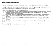
... the heating season and a higher temperature during the cooling season). There is an individual key for each of the four program periods: Wake -The program period when you want the house at a comfortable temperature when you get up and while you are sleeping. (This is located behind the thermostat cover. STEP 10. The thermostat displays day, time, program period, temperature and system settings. The three most frequently used...
... the heating season and a higher temperature during the cooling season). There is an individual key for each of the four program periods: Wake -The program period when you want the house at a comfortable temperature when you get up and while you are sleeping. (This is located behind the thermostat cover. STEP 10. The thermostat displays day, time, program period, temperature and system settings. The three most frequently used...
Owner's Manual
Page 16
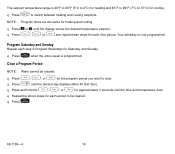
The setpoint temperature range is programmed. q Press , , or Leave Return Sleep for Saturday and Sunday. q Press Day until the display shows the desired temperature setpoint. q Press or until the desired day displays (Mon-Fri Sat; q Heat/Cool Press Settings to clear. Program Saturday and Sunday Repeat each time period. Sun). NOTE: Program times are the same for approximately 3 seconds until the time and temperature clear. q Press , Leave Return or Sleep and repeat these steps...
The setpoint temperature range is programmed. q Press , , or Leave Return Sleep for Saturday and Sunday. q Press Day until the display shows the desired temperature setpoint. q Press or until the desired day displays (Mon-Fri Sat; q Heat/Cool Press Settings to clear. Program Saturday and Sunday Repeat each time period. Sun). NOTE: Program times are the same for approximately 3 seconds until the time and temperature clear. q Press , Leave Return or Sleep and repeat these steps...
Owner's Manual
Page 17
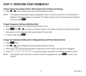
... designated time, press Run Program to return to the desired position (Heat or Cool). OPERATING YOUR THERMOSTAT Change Temperature Setting Until the Next Program Period (Temporary Change) q Press or until the display shows the desired temperature setpoint. q Run To cancel "Hold" press Program . q Press or until the screen shows the desired temperature setting. STEP 11. q Press Hold Temp then or to change your setting if desired. (The display changes from showing the setpoint temperature to restart. Change the Temperature Setting Until a Designated Day...
... designated time, press Run Program to return to the desired position (Heat or Cool). OPERATING YOUR THERMOSTAT Change Temperature Setting Until the Next Program Period (Temporary Change) q Press or until the display shows the desired temperature setpoint. q Run To cancel "Hold" press Program . q Press or until the screen shows the desired temperature setting. STEP 11. q Press Hold Temp then or to change your setting if desired. (The display changes from showing the setpoint temperature to restart. Change the Temperature Setting Until a Designated Day...
Owner's Manual
Page 18
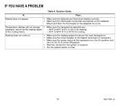
... Fan Auto Heat System Heat System Off Cool Off Cool Heat System Off Cool 69-1199-4 18 STEP 12. Fan On: The fan runs continuously. Fan Auto: Normal setting for more efficient central air cleaning. (In a heat-only system, fan runs continuously only if fan relay is connected to the G thermostat terminal). Use for improved air circulation or for most homes. SET THE FAN AND SYSTEM SWITCHES First set the system switch. The equipment controls the fan operation. Cool: The thermostat controls your heating system. Then set the fan switch...
... Fan Auto Heat System Heat System Off Cool Off Cool Heat System Off Cool 69-1199-4 18 STEP 12. Fan On: The fan runs continuously. Fan Auto: Normal setting for more efficient central air cleaning. (In a heat-only system, fan runs continuously only if fan relay is connected to the G thermostat terminal). Use for improved air circulation or for most homes. SET THE FAN AND SYSTEM SWITCHES First set the system switch. The equipment controls the fan operation. Cool: The thermostat controls your heating system. Then set the fan switch...
Owner's Manual
Page 19
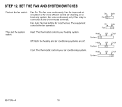
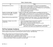
IF YOU HAVE A PROBLEM Table 4. Display does not appear. • • Temperature settings will not change • (example; Make sure the thermostat is mounted and latched on . • • • • • Then... Wait five minutes for the system to Heat. 19 69-1199-4 Make sure the temperature setpoints are fresh and installed correctly. Make sure the power switch at the equipment is...
IF YOU HAVE A PROBLEM Table 4. Display does not appear. • • Temperature settings will not change • (example; Make sure the thermostat is mounted and latched on . • • • • • Then... Wait five minutes for the system to Heat. 19 69-1199-4 Make sure the temperature setpoints are fresh and installed correctly. Make sure the power switch at the equipment is...
Owner's Manual
Page 20
... gas). • Location and number of wires connected to www.honeywell.com/yourhome or call Honeywell Customer Care at the wrong times. If... If all of thermostat). • Thermostat date code. (Located below the room temperature. • Make sure the circuit breaker is not tripped, and reset it is 40°F to 90°F (4.5°C to Cool. Temperature setting limit has been reached. Solution Guide. The heating setting range is...
... gas). • Location and number of wires connected to www.honeywell.com/yourhome or call Honeywell Customer Care at the wrong times. If... If all of thermostat). • Thermostat date code. (Located below the room temperature. • Make sure the circuit breaker is not tripped, and reset it is 40°F to 90°F (4.5°C to Cool. Temperature setting limit has been reached. Solution Guide. The heating setting range is...
Owner's Manual
Page 21
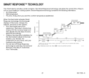
... Mon Wake System Heat Room 66 F 64 F System Operating in Energy Savings Mode Recovery Begins Mon System Heat AM Heat Sleep In Recovery Mon System Heat Room AM Heat Sleep In Recovery 1 Room 62 F Mon System Heat AM Sleep 5:00 Room 5:30 6:00 6:30 ENERGY SAVINGS PERIOD RECOVERY FROM ENERGY SAVINGS TIME COMFORT PERIOD THERMOSTAT USES THE SAME SCHEME TO RETURN TO LOWER COMFORT TEMPERATURE DURING THE COOLING SEASON. 1 IF In Recovery IS DISPLAYED, PRESS TO...
... Mon Wake System Heat Room 66 F 64 F System Operating in Energy Savings Mode Recovery Begins Mon System Heat AM Heat Sleep In Recovery Mon System Heat Room AM Heat Sleep In Recovery 1 Room 62 F Mon System Heat AM Sleep 5:00 Room 5:30 6:00 6:30 ENERGY SAVINGS PERIOD RECOVERY FROM ENERGY SAVINGS TIME COMFORT PERIOD THERMOSTAT USES THE SAME SCHEME TO RETURN TO LOWER COMFORT TEMPERATURE DURING THE COOLING SEASON. 1 IF In Recovery IS DISPLAYED, PRESS TO...
Owner's Manual
Page 22
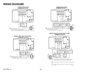
...-4 HEATING COOLING FAN RELAY OR CONTACTOR RELAY 1 VALVE COIL COIL 1 POWER SUPPLY. M12739 M10617 4-WIRE SINGLE-STAGE HEAT PUMP (JUMPER INTACT) THERMOSTAT B RC O W Y R G 3 22 2 COMPRESSOR HEAT CHANGEOVER CONTACTOR 2 VALVE 1 COOL CHANGEOVER FAN VALVE RELAY 1 POWER SUPPLY. PROVIDE DISCONNECT MEANS AND OVERLOAD PROTECTION AS REQUIRED. 2 USE EITHER O OR B FOR HEAT PUMP CHANGEOVER. 3 USING A JUMPER WIRE (NOT SUPPLIED) CONNECT W TO Y. WIRING DIAGRAMS 2-WIRE HEAT-ONLY (JUMPER INTACT) THERMOSTAT B RC O W Y R G 4-WIRE HEAT/COOL (JUMPER INTACT) THERMOSTAT B RC...
...-4 HEATING COOLING FAN RELAY OR CONTACTOR RELAY 1 VALVE COIL COIL 1 POWER SUPPLY. M12739 M10617 4-WIRE SINGLE-STAGE HEAT PUMP (JUMPER INTACT) THERMOSTAT B RC O W Y R G 3 22 2 COMPRESSOR HEAT CHANGEOVER CONTACTOR 2 VALVE 1 COOL CHANGEOVER FAN VALVE RELAY 1 POWER SUPPLY. PROVIDE DISCONNECT MEANS AND OVERLOAD PROTECTION AS REQUIRED. 2 USE EITHER O OR B FOR HEAT PUMP CHANGEOVER. 3 USING A JUMPER WIRE (NOT SUPPLIED) CONNECT W TO Y. WIRING DIAGRAMS 2-WIRE HEAT-ONLY (JUMPER INTACT) THERMOSTAT B RC O W Y R G 4-WIRE HEAT/COOL (JUMPER INTACT) THERMOSTAT B RC...
Owner's Manual
Page 23
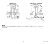
5-WIRE HEAT/COOL (JUMPER REMOVED) THERMOSTAT B RC O W Y R G 5-WIRE HEAT/COOL WITH DAMPER (JUMPER INTACT) THERMOSTAT B RC O W Y R G HEATING RELAY OR VALVE COIL 1 FAN RELAY COOLING CONTACTOR COIL 1 1 POWER SUPPLY. M10619 HEAT DAMPER HEAT RELAY COMPRESSOR CONTACTOR COOL DAMPER 1 POWER SUPPLY. PROVIDE DISCONNECT MEANS AND OVERLOAD PROTECTION AS REQUIRED. FAN RELAY 1 M18738 Notice: This thermostat is a Class B digital apparatus that complies with Canadian Radio Interference Regulations, CRC c. 1374. 23 69-1199-4 PROVIDE DISCONNECT MEANS AND OVERLOAD PROTECTION AS...
5-WIRE HEAT/COOL (JUMPER REMOVED) THERMOSTAT B RC O W Y R G 5-WIRE HEAT/COOL WITH DAMPER (JUMPER INTACT) THERMOSTAT B RC O W Y R G HEATING RELAY OR VALVE COIL 1 FAN RELAY COOLING CONTACTOR COIL 1 1 POWER SUPPLY. M10619 HEAT DAMPER HEAT RELAY COMPRESSOR CONTACTOR COOL DAMPER 1 POWER SUPPLY. PROVIDE DISCONNECT MEANS AND OVERLOAD PROTECTION AS REQUIRED. FAN RELAY 1 M18738 Notice: This thermostat is a Class B digital apparatus that complies with Canadian Radio Interference Regulations, CRC c. 1374. 23 69-1199-4 PROVIDE DISCONNECT MEANS AND OVERLOAD PROTECTION AS...

