
Owner's Manual
Page 1
Wire Wallplate Terminals ...8 Step 5. Customize Your Thermostat ...11 Step 9. Programming ...14 Step 11. Pour obtenir ce ode demploi en français, composer le 1-800-468-1502. Remove Old Thermostat...6 Step 3. Registered Trademark © 2004 Honeywell International Inc. Honeywell CT3500/CT3595 PROGRAMMABLE THERMOSTAT Weekday, Saturday and Sunday Programmable Heat and/or Cool Low Voltage (20...
Wire Wallplate Terminals ...8 Step 5. Customize Your Thermostat ...11 Step 9. Programming ...14 Step 11. Pour obtenir ce ode demploi en français, composer le 1-800-468-1502. Remove Old Thermostat...6 Step 3. Registered Trademark © 2004 Honeywell International Inc. Honeywell CT3500/CT3595 PROGRAMMABLE THERMOSTAT Weekday, Saturday and Sunday Programmable Heat and/or Cool Low Voltage (20...
Owner's Manual
Page 5
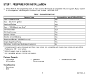
... must be heating only. Not compatible with CT3500/CT3595 Gas - PREPARE FOR INSTALLATION q Check Table 1, the compatibility chart, to make sure the thermostat is not compatible, call Honeywell Customer Care, toll-free, 1-800-468-1502. Standing Pilot Yes Gas - Table 1. Compatibility Chart. STEP 1. c Not compatible with 2-wire Honeywell and Taco zone valves. Electronic Ignition...
... must be heating only. Not compatible with CT3500/CT3595 Gas - PREPARE FOR INSTALLATION q Check Table 1, the compatibility chart, to make sure the thermostat is not compatible, call Honeywell Customer Care, toll-free, 1-800-468-1502. Standing Pilot Yes Gas - Table 1. Compatibility Chart. STEP 1. c Not compatible with 2-wire Honeywell and Taco zone valves. Electronic Ignition...
Owner's Manual
Page 6
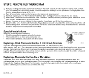
... not need to it. • Thermostat in a heating only system with the old terminal designation. q Carefully unpack your system, call Honeywell Customer Care at the furnace or the fuse/circuit breaker panel. As you probably have a variation of a multistage heat pump or other multistage...the cover does not snap off power to the wallplate and lift the thermostat away. WIRES THROUGH WALL OPENING Replacing a Clock Thermostat that has Six or More Wires If there are replacing a Honeywell Chronotherm® Thermostat, you can damage the transformer. Do not wrap them separately using...
... not need to it. • Thermostat in a heating only system with the old terminal designation. q Carefully unpack your system, call Honeywell Customer Care at the furnace or the fuse/circuit breaker panel. As you probably have a variation of a multistage heat pump or other multistage...the cover does not snap off power to the wallplate and lift the thermostat away. WIRES THROUGH WALL OPENING Replacing a Clock Thermostat that has Six or More Wires If there are replacing a Honeywell Chronotherm® Thermostat, you can damage the transformer. Do not wrap them separately using...
Owner's Manual
Page 7
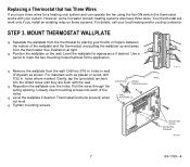
... will work only if you have three wires. Use a pencil to mark the two mounting holes that has Three Wires If you install an isolating relay on the wall. holes where marked. Pull the wires through the WIRES THROUGH WALL wiring opening. q Position the wallplate on these...STEP 3. For materials such as shown. Drill two 3/16 in . However, some hot water (zoned) heating systems also have three wires for appearance if desired. MOUNT THERMOSTAT WALLPLATE q Separate the wallplate from the thermostat by placing your system. Loosely insert mounting screws into...
... will work only if you have three wires. Use a pencil to mark the two mounting holes that has Three Wires If you install an isolating relay on the wall. holes where marked. Pull the wires through the WIRES THROUGH WALL wiring opening. q Position the wallplate on these...STEP 3. For materials such as shown. Drill two 3/16 in . However, some hot water (zoned) heating systems also have three wires for appearance if desired. MOUNT THERMOSTAT WALLPLATE q Separate the wallplate from the thermostat by placing your system. Loosely insert mounting screws into...
Owner's Manual
Page 8
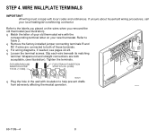
... R q Loosen the terminal screws. M4826 q Plug the hole in the wall with insulation to both acceptable, (see illustration). q For wiring diagrams, if needed, see illustration). Tighten the terminals. FOR STRAIGHT INSERTION STRIP 5/16 IN. (8 MM). M16425 69-1199-4 8 q... Remove the factory-installed jumper connecting terminals R and RC if wires are both of your local heating/air-conditioning contractor. q Match the letter of those terminals. Slip each wire beneath its matching W Y G terminal. Wraparound and straight connections are connected to...
... R q Loosen the terminal screws. M4826 q Plug the hole in the wall with insulation to both acceptable, (see illustration). q For wiring diagrams, if needed, see illustration). Tighten the terminals. FOR STRAIGHT INSERTION STRIP 5/16 IN. (8 MM). M16425 69-1199-4 8 q... Remove the factory-installed jumper connecting terminals R and RC if wires are both of your local heating/air-conditioning contractor. q Match the letter of those terminals. Slip each wire beneath its matching W Y G terminal. Wraparound and straight connections are connected to...
Owner's Manual
Page 9
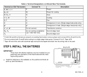
a If both O and B when wiring to a single stage heat pump. b Do not connect both RH and R terminals are present on existing thermostat, remove jumper and connect Rh to R and R to O. ...). Terminal Designations on Old Thermostat Connect To Description R, RHa, 4, V R Power Rc, Ra Rc Power for programming and operation of the wire with electrical tape and push the taped wire back into the wiring hole in cool. (Single stage heat pump only). Terminal on Old and New Thermostats. Cc, Xc, Bb Do not connect...
a If both O and B when wiring to a single stage heat pump. b Do not connect both RH and R terminals are present on existing thermostat, remove jumper and connect Rh to R and R to O. ...). Terminal Designations on Old Thermostat Connect To Description R, RHa, 4, V R Power Rc, Ra Rc Power for programming and operation of the wire with electrical tape and push the taped wire back into the wiring hole in cool. (Single stage heat pump only). Terminal on Old and New Thermostats. Cc, Xc, Bb Do not connect...
Owner's Manual
Page 20
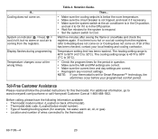
... settings are correct. • Reprogram any incorrect settings. Wait five minutes after seeing the flame or snowflake and check the registers again. If all of wires connected to On if it if necessary. • Make sure the system switch at the wrong times. The heating setting range is coming from the... 4. Cooling does not come on indicator ( = heat, = cool) is lit, but no warm or cool air is 40°F to 90°F (4.5°C to www.honeywell.com/yourhome or call Honeywell Customer Care at 1-800-468-1502.
... settings are correct. • Reprogram any incorrect settings. Wait five minutes after seeing the flame or snowflake and check the registers again. If all of wires connected to On if it if necessary. • Make sure the system switch at the wrong times. The heating setting range is coming from the... 4. Cooling does not come on indicator ( = heat, = cool) is lit, but no warm or cool air is 40°F to 90°F (4.5°C to www.honeywell.com/yourhome or call Honeywell Customer Care at 1-800-468-1502.
Owner's Manual
Page 22
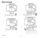
...PROTECTION AS REQUIRED. 2 USE EITHER O OR B FOR HEAT PUMP CHANGEOVER. 3 USING A JUMPER WIRE (NOT SUPPLIED) CONNECT W TO Y. PROVIDE DISCONNECT MEANS AND OVERLOAD PROTECTION AS REQUIRED. 1 M10616 3-WIRE HEAT ONLY WITH FAN (JUMPER INTACT) THERMOSTAT B RC O W Y R G HEATING RELAY OR ...VALVE COIL FAN RELAY 1 POWER SUPPLY. PROVIDE DISCONNECT MEANS AND OVERLOAD PROTECTION AS REQUIRED. M10617 4-WIRE SINGLE-STAGE HEAT PUMP (JUMPER INTACT) THERMOSTAT B RC O W Y R G 3 22 2 COMPRESSOR HEAT CHANGEOVER CONTACTOR 2 VALVE 1 COOL CHANGEOVER FAN...
...PROTECTION AS REQUIRED. 2 USE EITHER O OR B FOR HEAT PUMP CHANGEOVER. 3 USING A JUMPER WIRE (NOT SUPPLIED) CONNECT W TO Y. PROVIDE DISCONNECT MEANS AND OVERLOAD PROTECTION AS REQUIRED. 1 M10616 3-WIRE HEAT ONLY WITH FAN (JUMPER INTACT) THERMOSTAT B RC O W Y R G HEATING RELAY OR ...VALVE COIL FAN RELAY 1 POWER SUPPLY. PROVIDE DISCONNECT MEANS AND OVERLOAD PROTECTION AS REQUIRED. M10617 4-WIRE SINGLE-STAGE HEAT PUMP (JUMPER INTACT) THERMOSTAT B RC O W Y R G 3 22 2 COMPRESSOR HEAT CHANGEOVER CONTACTOR 2 VALVE 1 COOL CHANGEOVER FAN...
Owner's Manual
Page 23
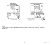
PROVIDE DISCONNECT MEANS AND OVERLOAD PROTECTION AS REQUIRED. 5-WIRE HEAT/COOL (JUMPER REMOVED) THERMOSTAT B RC O W Y R G 5-WIRE HEAT/COOL WITH DAMPER (JUMPER INTACT) THERMOSTAT B RC O W Y R G HEATING RELAY OR VALVE COIL 1 FAN RELAY COOLING CONTACTOR COIL 1 1 POWER SUPPLY. PROVIDE DISCONNECT MEANS AND OVERLOAD ...
PROVIDE DISCONNECT MEANS AND OVERLOAD PROTECTION AS REQUIRED. 5-WIRE HEAT/COOL (JUMPER REMOVED) THERMOSTAT B RC O W Y R G 5-WIRE HEAT/COOL WITH DAMPER (JUMPER INTACT) THERMOSTAT B RC O W Y R G HEATING RELAY OR VALVE COIL 1 FAN RELAY COOLING CONTACTOR COIL 1 1 POWER SUPPLY. PROVIDE DISCONNECT MEANS AND OVERLOAD ...


