Instruction Manual
Page 10
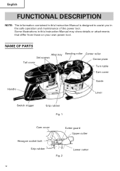
Some illustrations in the safe operation and maintenance of the power tool. NAME OF PARTS Allen key Set screws Tail cover Bending roller Center roller Center plate Turn table Cam cover Handle Guide Lever Switch trigger Grip rubber Fig. 1 Cam cover Cutter guard Upper cutter Hexagon socket bolt Grip rubber Fig. 2 Lower cutter 10 English FUNCTIONAL DESCRIPTION NOTE: The information contained in this Instruction Manual is designed to assist you in this Instruction Manual may show details or attachments that differ from those on your own power tool.
Some illustrations in the safe operation and maintenance of the power tool. NAME OF PARTS Allen key Set screws Tail cover Bending roller Center roller Center plate Turn table Cam cover Handle Guide Lever Switch trigger Grip rubber Fig. 1 Cam cover Cutter guard Upper cutter Hexagon socket bolt Grip rubber Fig. 2 Lower cutter 10 English FUNCTIONAL DESCRIPTION NOTE: The information contained in this Instruction Manual is designed to assist you in this Instruction Manual may show details or attachments that differ from those on your own power tool.
Instruction Manual
Page 13
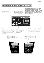
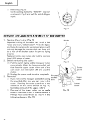
...least one full second before use. Avoid any work exceeding the maximum capacities. (Rebar diameter: #5 (5/8")) (Returning Halfway) 1 Select RETURN with the dial. 2 Pull the trigger. (Selecting the rebar size) Select the rebar size and the bending angle. 13 Begin operation only after it has been switched... off and then immediately turned on again after ensuring that there are no people within the turning range of the material to the cutter ...
...least one full second before use. Avoid any work exceeding the maximum capacities. (Rebar diameter: #5 (5/8")) (Returning Halfway) 1 Select RETURN with the dial. 2 Pull the trigger. (Selecting the rebar size) Select the rebar size and the bending angle. 13 Begin operation only after it has been switched... off and then immediately turned on again after ensuring that there are no people within the turning range of the material to the cutter ...
Instruction Manual
Page 15
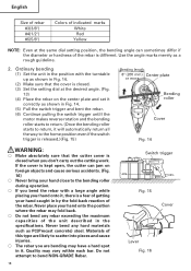
...worn grip rubber with new one when Fig. 6 replacing the cutter. ⅜ Note that the unit is released too early, the cutter will not return and the trigger will have a hard spot in it on the lower cutter. (5) When the rebar is set, make sure that the reaction stopper B is released ... you are likely to scatter into pieces and cause injuries. ⅜ The rebar you can free the rebar by bringing the upper cutter back up to run in serious injury. If the switch trigger is not a hand held tool. WARNING: Bending roller Grip Reaction rubber stopper A ⅜ While turning ...
...worn grip rubber with new one when Fig. 6 replacing the cutter. ⅜ Note that the unit is released too early, the cutter will not return and the trigger will have a hard spot in it on the lower cutter. (5) When the rebar is set, make sure that the reaction stopper B is released ... you are likely to scatter into pieces and cause injuries. ⅜ The rebar you can free the rebar by bringing the upper cutter back up to run in serious injury. If the switch trigger is not a hand held tool. WARNING: Bending roller Grip Reaction rubber stopper A ⅜ While turning ...
Instruction Manual
Page 16
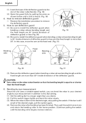
..."wear and tear", "deformation", "nicked edges", etc. Before removing the cutter (1) Pull the switch lightly and let the upper cutter move slowly. Replace it with a Phillips head screwdriver as shown in Fig. 8 and pull the switch trigger again. 0˚ RETURN 90˚ 45˚ CUT180˚ 135&#...the "RETURN" position as shown in the following diagram. (Fig. 11) Blade Fig. 9 Fig. 10 Cutter guard Upper cutter Lower cutter 16 Service life of cutter (Fig. 9) Repeated cutting of the rebar can be a fear of the cam cover, turn the switch OFF and stop the motor. 3. (2) Unplug...
..."wear and tear", "deformation", "nicked edges", etc. Before removing the cutter (1) Pull the switch lightly and let the upper cutter move slowly. Replace it with a Phillips head screwdriver as shown in Fig. 8 and pull the switch trigger again. 0˚ RETURN 90˚ 45˚ CUT180˚ 135&#...the "RETURN" position as shown in the following diagram. (Fig. 11) Blade Fig. 9 Fig. 10 Cutter guard Upper cutter Lower cutter 16 Service life of cutter (Fig. 9) Repeated cutting of the rebar can be a fear of the cam cover, turn the switch OFF and stop the motor. 3. (2) Unplug...
Instruction Manual
Page 18
...rough guideline. 2. Do not attempt to scatter into pieces and cause injuries. ⅜ The rebar you are likely to bend NON-GRADE Rebar. 18 Switch trigger Fig. 15 Cover Lever Fig. 16 If the cover is kept open, the cutter can jam on foreign objects and cause serious accidents. (Fig. 16) ⅜ Never ...close to the home position even if the switch trigger is released.)(Fig. 15) Bending length 8" (200 mm) Center plate or more Bending roller Cover Fig. 14 WARNING: ⅜ Make absolutely sure that the cutter cover is closed when you bend the rebar with the turntable up as shown in Fig. ...
...rough guideline. 2. Do not attempt to scatter into pieces and cause injuries. ⅜ The rebar you are likely to bend NON-GRADE Rebar. 18 Switch trigger Fig. 15 Cover Lever Fig. 16 If the cover is kept open, the cutter can jam on foreign objects and cause serious accidents. (Fig. 16) ⅜ Never ...close to the home position even if the switch trigger is released.)(Fig. 15) Bending length 8" (200 mm) Center plate or more Bending roller Cover Fig. 14 WARNING: ⅜ Make absolutely sure that the cutter cover is closed when you bend the rebar with the turntable up as shown in Fig. ...
Instruction Manual
Page 20
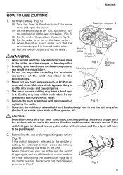
...more than 20". Bending by eye measurement Since the unit uses a variable-speed switch, you desire. (2) Pull the switch trigger lightly and bend the rebar slowly. (3) When the rebar is more and return the bending roller to the home position. (Continue pulling the switch until a click is heard. (Fig...fixed length is bent to the desired angle, stop pulling the switch. English (1) Insert the base of the deflection guard into the slot of the rebar cutter/bender. (Fig. 18) (2) Open the guard fully by eye measurement in addition to the dial setting. (1) Set the setting dial to a larger...
...more than 20". Bending by eye measurement Since the unit uses a variable-speed switch, you desire. (2) Pull the switch trigger lightly and bend the rebar slowly. (3) When the rebar is more and return the bending roller to the home position. (Continue pulling the switch until a click is heard. (Fig...fixed length is bent to the desired angle, stop pulling the switch. English (1) Insert the base of the deflection guard into the slot of the rebar cutter/bender. (Fig. 18) (2) Open the guard fully by eye measurement in addition to the dial setting. (1) Set the setting dial to a larger...


