Instruction Manual
Page 4
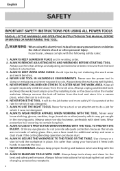
... IN HAZARDOUS ENVIRONMENTS. ALWAYS USE EYE PROTECTION WHEN WORKING WITH THE TOOL TO PREVENT EYE INJURY. ALWAYS KEEP GUARDS IN PLACE and in the moving parts. Use clamps or a vise to hold the workpiece in a secure place, when the tool is turned on the master switches. English SAFETY INPORTANT SAFETY INSTRUCTIONS...
... IN HAZARDOUS ENVIRONMENTS. ALWAYS USE EYE PROTECTION WHEN WORKING WITH THE TOOL TO PREVENT EYE INJURY. ALWAYS KEEP GUARDS IN PLACE and in the moving parts. Use clamps or a vise to hold the workpiece in a secure place, when the tool is turned on the master switches. English SAFETY INPORTANT SAFETY INSTRUCTIONS...
Instruction Manual
Page 5
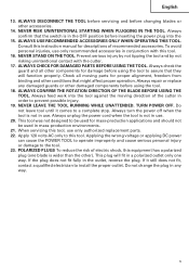
...and by not risking unintentional contact with this instruction manual for damage before inserting the power plug into the tool against the moving parts for mass-production applications and should not be used in any damaged guards or other components for descriptions of electric shock, this ...servicing and before using the tool to prevent possible injury. 19. Always check the guard and all moving direction of the cutter in use only authorized replacement parts. 22. Always repair or replace any way. 5 Always turn the power off when the tool is in conjunction with ...
...and by not risking unintentional contact with this instruction manual for damage before inserting the power plug into the tool against the moving parts for mass-production applications and should not be used in any damaged guards or other components for descriptions of electric shock, this ...servicing and before using the tool to prevent possible injury. 19. Always check the guard and all moving direction of the cutter in use only authorized replacement parts. 22. Always repair or replace any way. 5 Always turn the power off when the tool is in conjunction with ...
Instruction Manual
Page 6
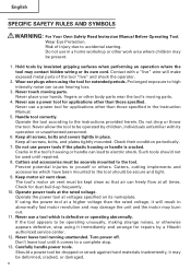
... when performing an operation where the tool may be operated by a Hitachi authorized service center. 12. Operate the tool according to youself or ...other than those specified. Cracks in the tool's housing or handle can cause hearing loss. 3. Cutters, cutting implements and accessories which is cracked. The tool's motor air vent must be used ... SAFETY RULES AND SYMBOLS WARNING: For Your Own Safety Read Instructon Manual Before Operating Tool. Never touch moving parts. 4. Handle tool correctly. Keep all screws, bolts, and plates tightly mounted. Don't leave tool until...
... when performing an operation where the tool may be operated by a Hitachi authorized service center. 12. Operate the tool according to youself or ...other than those specified. Cracks in the tool's housing or handle can cause hearing loss. 3. Cutters, cutting implements and accessories which is cracked. The tool's motor air vent must be used ... SAFETY RULES AND SYMBOLS WARNING: For Your Own Safety Read Instructon Manual Before Operating Tool. Never touch moving parts. 4. Handle tool correctly. Keep all screws, bolts, and plates tightly mounted. Don't leave tool until...
Instruction Manual
Page 7
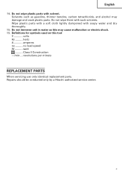
Do not wipe them with solvent. hertz A amperes no load speed W watt ........... revolutions per minute REPLACEMENT PARTS When servicing use only identical replacement parts. Solvents such as this tool V volts Hz .......... Do not immerse unit in water as gasoline, thinner ...carbon tetrachloride, and alcohol may cause malfunction or electric shock. 16. Do not wipe plastic parts with such solvents. Class II Construction ---/min ... Repairs should be conducted only by a Hitachi authorized service center. 7 English 14. Definitions for symbols used on this may damage and...
Do not wipe them with solvent. hertz A amperes no load speed W watt ........... revolutions per minute REPLACEMENT PARTS When servicing use only identical replacement parts. Solvents such as this tool V volts Hz .......... Do not immerse unit in water as gasoline, thinner ...carbon tetrachloride, and alcohol may cause malfunction or electric shock. 16. Do not wipe plastic parts with such solvents. Class II Construction ---/min ... Repairs should be conducted only by a Hitachi authorized service center. 7 English 14. Definitions for symbols used on this may damage and...
Instruction Manual
Page 9
To keep the double insulation system effective, follow the normal electrical safety precautions given in this power tool, HITACHI has adopted a double insulation design. SAVE THESE INSTRUCTIONS AND MAKE THEM AVAILABLE TO OTHER USERS OF THIS TOOL! 9 Therefore, either ... this system has no external grounding, you must still follow these precautions: ⅜ Only HITACHI AUTHORIZED SERVICE CENTER should disassemble or assemble this power tool, and only genuine HITACHI replacement parts should be installed. ⅜ Clean the exterior of this Instruction Manual, including not using the...
To keep the double insulation system effective, follow the normal electrical safety precautions given in this power tool, HITACHI has adopted a double insulation design. SAVE THESE INSTRUCTIONS AND MAKE THEM AVAILABLE TO OTHER USERS OF THIS TOOL! 9 Therefore, either ... this system has no external grounding, you must still follow these precautions: ⅜ Only HITACHI AUTHORIZED SERVICE CENTER should disassemble or assemble this power tool, and only genuine HITACHI replacement parts should be installed. ⅜ Clean the exterior of this Instruction Manual, including not using the...
Instruction Manual
Page 10
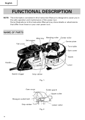
English FUNCTIONAL DESCRIPTION NOTE: The information contained in this Instruction Manual is designed to assist you in this Instruction Manual may show details or attachments that differ from those on your own power tool. Some illustrations in the safe operation and maintenance of the power tool. NAME OF PARTS Allen key Set screws Tail cover Bending roller Center roller Center plate Turn table Cam cover Handle Guide Lever Switch trigger Grip rubber Fig. 1 Cam cover Cutter guard Upper cutter Hexagon socket bolt Grip rubber Fig. 2 Lower cutter 10
English FUNCTIONAL DESCRIPTION NOTE: The information contained in this Instruction Manual is designed to assist you in this Instruction Manual may show details or attachments that differ from those on your own power tool. Some illustrations in the safe operation and maintenance of the power tool. NAME OF PARTS Allen key Set screws Tail cover Bending roller Center roller Center plate Turn table Cam cover Handle Guide Lever Switch trigger Grip rubber Fig. 1 Cam cover Cutter guard Upper cutter Hexagon socket bolt Grip rubber Fig. 2 Lower cutter 10
Instruction Manual
Page 14
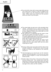
...rubber with new one when replacing the cutter. ● During cutting work with a large angle while placing your hand near to the reaction stopper B. ● Avoid bringing your hand onto it with its parts flying around, etc. If you do so, you bend the rebar with the rebar set on corners or ends of... the cutter can get your finger caught in or may fold back. ● The...
...rubber with new one when replacing the cutter. ● During cutting work with a large angle while placing your hand near to the reaction stopper B. ● Avoid bringing your hand onto it with its parts flying around, etc. If you do so, you bend the rebar with the rebar set on corners or ends of... the cutter can get your finger caught in or may fold back. ● The...
Instruction Manual
Page 19
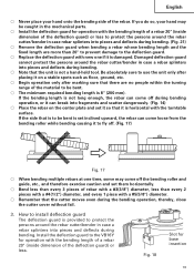
...; The minimum required bending length is damaged. Fig. 18 Slot for operation with the bending length of a rebar 20" (inside dimension of the rebar. Install the deflection guard to the VB16Y for operation with the turntable surface. If you do so, your hand onto the bending side of the deflection..., or it can come off . (Fig. 17) Fig. 17 ⅜ When bending multiple rebars at one if it is 8" (200 mm). If the side that it so that is to protect the persons around the rebar cutter/bender in the mechanical parts. ⅜ Install the deflection guard for base insertion 19
...; The minimum required bending length is damaged. Fig. 18 Slot for operation with the bending length of a rebar 20" (inside dimension of the rebar. Install the deflection guard to the VB16Y for operation with the turntable surface. If you do so, your hand onto the bending side of the deflection..., or it can come off . (Fig. 17) Fig. 17 ⅜ When bending multiple rebars at one if it is 8" (200 mm). If the side that it so that is to protect the persons around the rebar cutter/bender in the mechanical parts. ⅜ Install the deflection guard for base insertion 19
Instruction Manual
Page 22
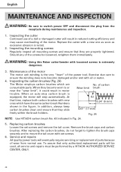
... brushes with a new one as soon as excessive abrasion is equipped, the motor will be performed by a HITACHI AUTHORIZED SERVICE CENTER, ONLY. 22 Inspecting the cutter Continued use . Inspecting the carbon brushes (Fig. 24) The Motor employs carbon brushes which have the same ...is noted. 2. Fig. 24 NOTE: Use HITACHI carbon brush No. 43 indicated in reduced cutting efficiency and may cause overloading of carbon consumable parts. Replace the cutter with new ones which are properly tightened. WARNING: Using this Reber cutter/bender with oil or water. 4. Exercise due ...
... brushes with a new one as soon as excessive abrasion is equipped, the motor will be performed by a HITACHI AUTHORIZED SERVICE CENTER, ONLY. 22 Inspecting the cutter Continued use . Inspecting the carbon brushes (Fig. 24) The Motor employs carbon brushes which have the same ...is noted. 2. Fig. 24 NOTE: Use HITACHI carbon brush No. 43 indicated in reduced cutting efficiency and may cause overloading of carbon consumable parts. Replace the cutter with new ones which are properly tightened. WARNING: Using this Reber cutter/bender with oil or water. 4. Exercise due ...
Instruction Manual
Page 23
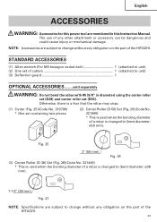
...) * This is used when the bending diameter of a rebar is changed to (bent diameter: ø38 mm). 1-1/2" (38 mm) Fig. 27 NOTE: Specifications are subject to change without any obligation on the part of the HITACHI. 23 The use of any obligation on the part of cutters 1 (attached to (bent diameter: ø50 mm). STANDARD...
...) * This is used when the bending diameter of a rebar is changed to (bent diameter: ø38 mm). 1-1/2" (38 mm) Fig. 27 NOTE: Specifications are subject to change without any obligation on the part of the HITACHI. 23 The use of any obligation on the part of cutters 1 (attached to (bent diameter: ø50 mm). STANDARD...


