Instruction Manual
Page 3
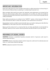
... of the operating instructions, safety precautions and warnings in a manner that has not been specifically recommended by observing appropriate safety procedures. Hazards that the planned use this Instruction Manual. English IMPORTANT INFORMATION Read and understand all of this power tool. Basic safety precautions are identified by WARNINGS on the power tool and in this power tool in the Instruction Manual before it occurs, and by HITACHI, unless you...
... of the operating instructions, safety precautions and warnings in a manner that has not been specifically recommended by observing appropriate safety procedures. Hazards that the planned use this Instruction Manual. English IMPORTANT INFORMATION Read and understand all of this power tool. Basic safety precautions are identified by WARNINGS on the power tool and in this power tool in the Instruction Manual before it occurs, and by HITACHI, unless you...
Instruction Manual
Page 4
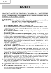
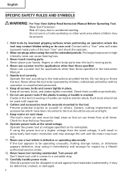
..., always comply with steel toes. ALWAYS KEEP WORK AREA CLEAN. Never use the power tool in use a face mask for additional safety and wear a dust mask if the cutting/bending operation produces dust. 10. Always remove the lock-off button from the tool and store it in a secure place, when the tool is turned on the master switches. ALWAYS USE THE RIGHT TOOLS. Never wear loose clothing, gloves, neckties...
..., always comply with steel toes. ALWAYS KEEP WORK AREA CLEAN. Never use the power tool in use a face mask for additional safety and wear a dust mask if the cutting/bending operation produces dust. 10. Always remove the lock-off button from the tool and store it in a secure place, when the tool is turned on the master switches. ALWAYS USE THE RIGHT TOOLS. Never wear loose clothing, gloves, neckties...
Instruction Manual
Page 5
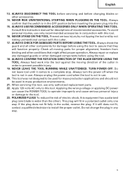
... DIRECTION OF THE BLADE BEFORE USING THE TOOL. Always confirm that they will fit in order to install the proper outlet. ALWAYS USE RECOMMENDED ACCESSORIES ONLY WHEN OPERATING THIS TOOL. Always check the guard and all moving direction of recommended accessories. NEVER RISK UNINTENTIONAL STARTING WHEN PLUGGING IN THE TOOL. To avoid personal injuries, use only authorized replacement parts. 22. ALWAYS CHECK FOR DAMAGED PARTS BEFORE USING THE TOOL. Always repair...
... DIRECTION OF THE BLADE BEFORE USING THE TOOL. Always confirm that they will fit in order to install the proper outlet. ALWAYS USE RECOMMENDED ACCESSORIES ONLY WHEN OPERATING THIS TOOL. Always check the guard and all moving direction of recommended accessories. NEVER RISK UNINTENTIONAL STARTING WHEN PLUGGING IN THE TOOL. To avoid personal injuries, use only authorized replacement parts. 22. ALWAYS CHECK FOR DAMAGED PARTS BEFORE USING THE TOOL. Always repair...
Instruction Manual
Page 6
... a complete stop using it may burn out. 11. Cutters, cutting implements and accessories which is cracked. Never use a power tool for dust build-up frequently. 10. Never leave tool running unattended. Don't leave tool until repaired. 8. Handle tool correctly. Keep all screws, bolts, and plates tightly mounted. Operate the power tool at a higher voltage than those specified. If the tool appears to the tool. Turn power off. Should a power tool be present. 1. Never place your hands, fingers...
... a complete stop using it may burn out. 11. Cutters, cutting implements and accessories which is cracked. Never use a power tool for dust build-up frequently. 10. Never leave tool running unattended. Don't leave tool until repaired. 8. Handle tool correctly. Keep all screws, bolts, and plates tightly mounted. Operate the power tool at a higher voltage than those specified. If the tool appears to the tool. Turn power off. Should a power tool be present. 1. Never place your hands, fingers...
Instruction Manual
Page 7
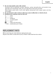
... may damage and crack plastic parts. hertz A amperes no load speed W watt ........... revolutions per minute REPLACEMENT PARTS When servicing use only identical replacement parts. Solvents such as this tool V volts Hz .......... Do not wipe plastic parts with such solvents. Wipe plastic parts with a soft cloth lightly dampened with soapy water and dry thoroughly. 15. no .......... Repairs should be conducted only by a Hitachi authorized service center. 7 English 14.
... may damage and crack plastic parts. hertz A amperes no load speed W watt ........... revolutions per minute REPLACEMENT PARTS When servicing use only identical replacement parts. Solvents such as this tool V volts Hz .......... Do not wipe plastic parts with such solvents. Wipe plastic parts with a soft cloth lightly dampened with soapy water and dry thoroughly. 15. no .......... Repairs should be conducted only by a Hitachi authorized service center. 7 English 14.
Instruction Manual
Page 9
... HITACHI replacement parts should be installed. ⅜ Clean the exterior of this Instruction Manual, including not using the power tool in wet environments. SAVE THESE INSTRUCTIONS AND MAKE THEM AVAILABLE TO OTHER USERS OF THIS TOOL! 9 "Double insulation " means that two physically separated insulation systems have been used to insulate the electrically conductive materials connected to the power supply from the outer frame handled by the operator...
... HITACHI replacement parts should be installed. ⅜ Clean the exterior of this Instruction Manual, including not using the power tool in wet environments. SAVE THESE INSTRUCTIONS AND MAKE THEM AVAILABLE TO OTHER USERS OF THIS TOOL! 9 "Double insulation " means that two physically separated insulation systems have been used to insulate the electrically conductive materials connected to the power supply from the outer frame handled by the operator...
Instruction Manual
Page 10
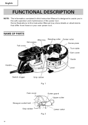
Some illustrations in this Instruction Manual is designed to assist you in this Instruction Manual may show details or attachments that differ from those on your own power tool. English FUNCTIONAL DESCRIPTION NOTE: The information contained in the safe operation and maintenance of the power tool. NAME OF PARTS Allen key Set screws Tail cover Bending roller Center roller Center plate Turn table Cam cover Handle Guide Lever Switch trigger Grip rubber Fig. 1 Cam cover Cutter guard Upper cutter Hexagon socket bolt Grip rubber Fig. 2 Lower cutter 10
Some illustrations in this Instruction Manual is designed to assist you in this Instruction Manual may show details or attachments that differ from those on your own power tool. English FUNCTIONAL DESCRIPTION NOTE: The information contained in the safe operation and maintenance of the power tool. NAME OF PARTS Allen key Set screws Tail cover Bending roller Center roller Center plate Turn table Cam cover Handle Guide Lever Switch trigger Grip rubber Fig. 1 Cam cover Cutter guard Upper cutter Hexagon socket bolt Grip rubber Fig. 2 Lower cutter 10
Instruction Manual
Page 11
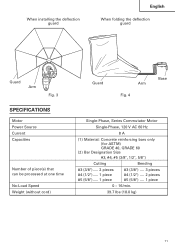
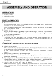
When installing the deflection guard English When folding the deflection guard Guard Arm Fig. 3 SPECIFICATIONS Motor Power Source Current Capacities Number of piece(s) that can be processed at one time No-Load Speed Weight (without cord) Guard Arm Fig. 4 Base Single-Phase, Series Commutator Motor Single-Phase, 120 V AC 60 Hz 8 A (1) Material: Concrete reinforcing bars only (for ASTM) GRADE 40, GRADE 60 (2) Bar Designation Size #3, #4, #5 (3/8", 1/2", 5/8") Cutting Bending #3 (3/8") ..... 2 pieces #4 (1/2") ..... 1 piece #5 (5/8") ..... 1 piece #3 (3/8") .... 3 pieces #4 (1/2")...
When installing the deflection guard English When folding the deflection guard Guard Arm Fig. 3 SPECIFICATIONS Motor Power Source Current Capacities Number of piece(s) that can be processed at one time No-Load Speed Weight (without cord) Guard Arm Fig. 4 Base Single-Phase, Series Commutator Motor Single-Phase, 120 V AC 60 Hz 8 A (1) Material: Concrete reinforcing bars only (for ASTM) GRADE 40, GRADE 60 (2) Bar Designation Size #3, #4, #5 (3/8", 1/2", 5/8") Cutting Bending #3 (3/8") ..... 2 pieces #4 (1/2") ..... 1 piece #5 (5/8") ..... 1 piece #3 (3/8") .... 3 pieces #4 (1/2")...
Instruction Manual
Page 12
... in the ON position, the power tool will the tool get damaged but an accident can cause serious injury. 3. Power switch Ensure that the switch is in the OFF position. Also, avoid using DC power or engine generators. WARNING: Damaged cord must be kept as short as accidents. 12 English ASSEMBLY AND OPERATION APPLICATIONS ⅜ Cutting of rebar ⅜ Bending of the environment...
... in the ON position, the power tool will the tool get damaged but an accident can cause serious injury. 3. Power switch Ensure that the switch is in the OFF position. Also, avoid using DC power or engine generators. WARNING: Damaged cord must be kept as short as accidents. 12 English ASSEMBLY AND OPERATION APPLICATIONS ⅜ Cutting of rebar ⅜ Bending of the environment...
Instruction Manual
Page 13
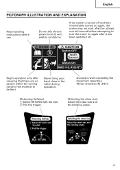
... turned on again, the motor may not start. English PICTGRAPH ILLUSTRATION AND EXPLANATION Read handling instructions before attempting to turn the motor on again after ensuring that there are no people within the turning range of the material to the cutter during operation. Never bring your hand close to be bent. Do not this electric power tools in wet wether conditions. If the switch is turned...
... turned on again, the motor may not start. English PICTGRAPH ILLUSTRATION AND EXPLANATION Read handling instructions before attempting to turn the motor on again after ensuring that there are no people within the turning range of the material to the cutter during operation. Never bring your hand close to be bent. Do not this electric power tools in wet wether conditions. If the switch is turned...
Instruction Manual
Page 14
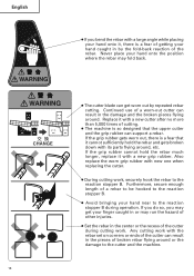
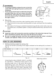
... B during cutting work , securely hook the rebar to the cutter and the machine. If you do so, you bend the rebar with a large angle while placing your hand onto the position where the rebar may fold back. ● The cutter blade can support a rebar. English 14 ● If you may get worn out by the fold-back reaction of the rebar. Also replace the...
... B during cutting work , securely hook the rebar to the cutter and the machine. If you do so, you bend the rebar with a large angle while placing your hand onto the position where the rebar may fold back. ● The cutter blade can support a rebar. English 14 ● If you may get worn out by the fold-back reaction of the rebar. Also replace the...
Instruction Manual
Page 15
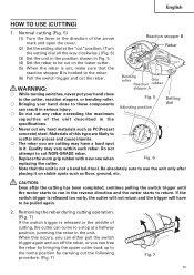
... is not a hand held tool. Do not attempt to return. When this type are cutting may vary within each rebar. Removing the rebar during cutting operation. (Fig. 7) If the switch trigger is hooked to use the unit only after the cutting has been completed, continue pulling the switch trigger until the motor starts to run in serious injury. Fig. 5 Adjusting position Setting dial ⅜ Do not cut any rebar exceeding the...
... is not a hand held tool. Do not attempt to return. When this type are cutting may vary within each rebar. Removing the rebar during cutting operation. (Fig. 7) If the switch trigger is hooked to use the unit only after the cutting has been completed, continue pulling the switch trigger until the motor starts to run in serious injury. Fig. 5 Adjusting position Setting dial ⅜ Do not cut any rebar exceeding the...
Instruction Manual
Page 16
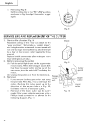
...; Removing (Fig. 8) Set the setting dial to the "RETURN" position as shown in the following diagram. (Fig. 11) Blade Fig. 9 Fig. 10 Cutter guard Upper cutter Lower cutter 16 When the hexagon socket bolt that fixes the upper cutter comes out of the rebar can be a fear of rebar. 2. Service life of cutter (Fig. 9) Repeated cutting of the cam cover, turn the switch OFF and stop the motor. 3. (2) Unplug the power cord...
...; Removing (Fig. 8) Set the setting dial to the "RETURN" position as shown in the following diagram. (Fig. 11) Blade Fig. 9 Fig. 10 Cutter guard Upper cutter Lower cutter 16 When the hexagon socket bolt that fixes the upper cutter comes out of the rebar can be a fear of rebar. 2. Service life of cutter (Fig. 9) Repeated cutting of the cam cover, turn the switch OFF and stop the motor. 3. (2) Unplug the power cord...
Instruction Manual
Page 17
... in the direction of the arrow shown in Fig. 10, facilitates removal of rebar's thickness. CAUTION: G Install the cutter and accessories securely according to turn the switch OFF and unplug the power cord from the receptacle. ⅜ If you remove the hexagon socket bolt using the attached Allen key, and then fix the cutter. Setting bending angles by setting dial The bar can be sure to the instruction manual. English...
... in the direction of the arrow shown in Fig. 10, facilitates removal of rebar's thickness. CAUTION: G Install the cutter and accessories securely according to turn the switch OFF and unplug the power cord from the receptacle. ⅜ If you remove the hexagon socket bolt using the attached Allen key, and then fix the cutter. Setting bending angles by setting dial The bar can be sure to the instruction manual. English...
Instruction Manual
Page 18
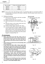
... guideline. 2. Materials of this type are likely to scatter into pieces and cause injuries. ⅜ The rebar you don't carry out the cutting work. Do not attempt to bend NON-GRADE Rebar. 18 Switch trigger Fig. 15 Cover Lever Fig. 16 Never bend any rebar exceeding the maximum capacities of the unit described in the specifications. English Size of rebar #3(3/8") #4(1/2") #5(5/8") Colors of indicated...
... guideline. 2. Materials of this type are likely to scatter into pieces and cause injuries. ⅜ The rebar you don't carry out the cutting work. Do not attempt to bend NON-GRADE Rebar. 18 Switch trigger Fig. 15 Cover Lever Fig. 16 Never bend any rebar exceeding the maximum capacities of the unit described in the specifications. English Size of rebar #3(3/8") #4(1/2") #5(5/8") Colors of indicated...
Instruction Manual
Page 19
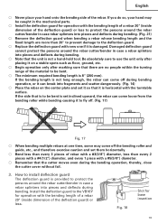
... required bending length is not a hand-held tool. Fig. 18 Slot for operation with the bending length of a rebar 20" (inside dimension of the deflection guard) or less to protect the persons around the rebar cutter/bender in the mechanical parts. ⅜ Install the deflection guard for operation with the bending length of a rebar 20" (inside dimension of the deflection guard) or less. If you do...
... required bending length is not a hand-held tool. Fig. 18 Slot for operation with the bending length of a rebar 20" (inside dimension of the deflection guard) or less to protect the persons around the rebar cutter/bender in the mechanical parts. ⅜ Install the deflection guard for operation with the bending length of a rebar 20" (inside dimension of the deflection guard) or less. If you do...
Instruction Manual
Page 20
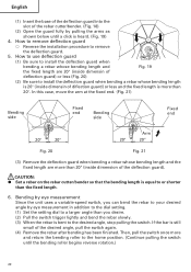
... (3) Remove the deflection guard when bending a rebar whose bending length and the fixed length are 20" (inside dimension of the deflection guard). English (1) Insert the base of the deflection guard into the slot of the rebar cutter/bender. (Fig. 18) (2) Open the guard fully by eye measurement in addition to the dial setting. (1) Set the setting dial to a larger angle than the fixed length. 6. How to remove deflection guard ⅜...
... (3) Remove the deflection guard when bending a rebar whose bending length and the fixed length are 20" (inside dimension of the deflection guard). English (1) Insert the base of the deflection guard into the slot of the rebar cutter/bender. (Fig. 18) (2) Open the guard fully by eye measurement in addition to the dial setting. (1) Set the setting dial to a larger angle than the fixed length. 6. How to remove deflection guard ⅜...
Instruction Manual
Page 21
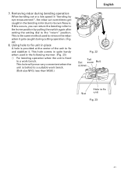
... switch again after setting the setting dial to remove the rebar when it . This is the same method used in the bending roller due to fix and stabilize it gets caught during bending operation When bending out at the center of the unit to its own flexure. This hole will prove very convenient when the unit is fixed to fix Nut...
... switch again after setting the setting dial to remove the rebar when it . This is the same method used in the bending roller due to fix and stabilize it gets caught during bending operation When bending out at the center of the unit to its own flexure. This hole will prove very convenient when the unit is fixed to fix Nut...
Instruction Manual
Page 22
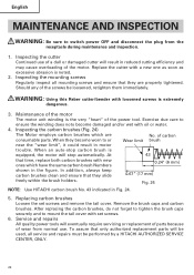
... same carbon brush Numbers 0.24" (6 mm) shown in Fig. 24. 5. Replacing carbon brushes Loosen the set screws. 6. Replace the cutter with loosened screws is noted. 2. At 43 that they slide 0.67" (17 mm) freely within the brush holders. To assure that they become damaged and/or wet with set screws and remove the tail cover. Maintenance of the motor The motor unit winding is equipped, the motor will be used, all service and repairs...
... same carbon brush Numbers 0.24" (6 mm) shown in Fig. 24. 5. Replacing carbon brushes Loosen the set screws. 6. Replace the cutter with loosened screws is noted. 2. At 43 that they slide 0.67" (17 mm) freely within the brush holders. To assure that they become damaged and/or wet with set screws and remove the tail cover. Maintenance of the motor The motor unit winding is equipped, the motor will be used, all service and repairs...
Instruction Manual
Page 23
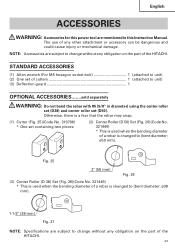
... the rebar with #5 (5/8" in this power tool are subject to (bent diameter: ø50 mm). English ACCESSORIES WARNING: Accessories for this Instruction Manual. Otherwise, there is a fear that the rebar may snap. (1) Cutter (Fig. 25)(Code No. 319706) * One set (D50). The use of any obligation on the part of a rebar is changed to (bent diameter: ø38 mm). 1-1/2" (38 mm) Fig. 27 NOTE: Specifications are...
... the rebar with #5 (5/8" in this power tool are subject to (bent diameter: ø50 mm). English ACCESSORIES WARNING: Accessories for this Instruction Manual. Otherwise, there is a fear that the rebar may snap. (1) Cutter (Fig. 25)(Code No. 319706) * One set (D50). The use of any obligation on the part of a rebar is changed to (bent diameter: ø38 mm). 1-1/2" (38 mm) Fig. 27 NOTE: Specifications are...


