Instruction Manual
Page 10
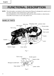
Some illustrations in this Instruction Manual is designed to assist you in this Instruction Manual may show details or attachments that differ from those on your own power tool. NAME OF PARTS Allen key Set screws Tail cover Bending roller Center roller Center plate Turn table Cam cover Handle Guide Lever Switch trigger Grip rubber Fig. 1 Cam cover Cutter guard Upper cutter Hexagon socket bolt Grip rubber Fig. 2 Lower cutter 10 English FUNCTIONAL DESCRIPTION NOTE: The information contained in the safe operation and maintenance of the power tool.
Some illustrations in this Instruction Manual is designed to assist you in this Instruction Manual may show details or attachments that differ from those on your own power tool. NAME OF PARTS Allen key Set screws Tail cover Bending roller Center roller Center plate Turn table Cam cover Handle Guide Lever Switch trigger Grip rubber Fig. 1 Cam cover Cutter guard Upper cutter Hexagon socket bolt Grip rubber Fig. 2 Lower cutter 10 English FUNCTIONAL DESCRIPTION NOTE: The information contained in the safe operation and maintenance of the power tool.
Instruction Manual
Page 13
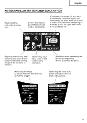
... then immediately turned on again after ensuring that there are no people within the turning range of the material to the cutter during operation. Wait for at least one full second before use. English PICTGRAPH ILLUSTRATION AND EXPLANATION Read handling instructions before ...again, the motor may not start. Avoid any work exceeding the maximum capacities. (Rebar diameter: #5 (5/8")) (Returning Halfway) 1 Select RETURN with the dial. 2 Pull the trigger. (Selecting the rebar size) Select the rebar size and the bending angle. 13 Do not this electric power tools in wet wether...
... then immediately turned on again after ensuring that there are no people within the turning range of the material to the cutter during operation. Wait for at least one full second before use. English PICTGRAPH ILLUSTRATION AND EXPLANATION Read handling instructions before ...again, the motor may not start. Avoid any work exceeding the maximum capacities. (Rebar diameter: #5 (5/8")) (Returning Halfway) 1 Select RETURN with the dial. 2 Pull the trigger. (Selecting the rebar size) Select the rebar size and the bending angle. 13 Do not this electric power tools in wet wether...
Instruction Manual
Page 15
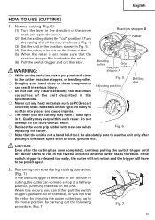
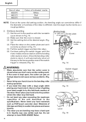
... the position shown in it on the lower cutter. (5) When the rebar is set, make sure that the unit is released too early, the cutter will not return and the trigger will have a hard spot in Fig. 5. (4) Set the rebar to be cut NON-GRADE rebar. ⅜ Replace the worn grip rubber with... new one when Fig. 6 replacing the cutter. ⅜ Note that the reaction stopper B is ...
... the position shown in it on the lower cutter. (5) When the rebar is set, make sure that the unit is released too early, the cutter will not return and the trigger will have a hard spot in Fig. 5. (4) Set the rebar to be cut NON-GRADE rebar. ⅜ Replace the worn grip rubber with... new one when Fig. 6 replacing the cutter. ⅜ Note that the reaction stopper B is ...
Instruction Manual
Page 16
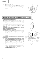
...the switch OFF and stop the motor. 3. (2) Unplug the power cord from the receptacle. Before removing the cutter (1) Pull the switch lightly and let the upper cutter move slowly. Removal Hexagon socket ⅜ If you remove the hexagon socket bolt using bolt the provided Allen key... hexagon socket bolt that fixes the upper cutter comes out of rebar. 2. Service life of cutter (Fig. 9) Repeated cutting of the rebar can remove the cutter. (Pushing the cutter guard up in the direction of the arrow shown in Fig. 8 and pull the switch trigger again. 0˚ RETURN 90˚ ...
...the switch OFF and stop the motor. 3. (2) Unplug the power cord from the receptacle. Before removing the cutter (1) Pull the switch lightly and let the upper cutter move slowly. Removal Hexagon socket ⅜ If you remove the hexagon socket bolt using bolt the provided Allen key... hexagon socket bolt that fixes the upper cutter comes out of rebar. 2. Service life of cutter (Fig. 9) Repeated cutting of the rebar can remove the cutter. (Pushing the cutter guard up in the direction of the arrow shown in Fig. 8 and pull the switch trigger again. 0˚ RETURN 90˚ ...
Instruction Manual
Page 18
... starts to return, it will automatically return all the way to scatter into pieces and cause injuries. ⅜ The rebar you are likely to the home position even if the switch trigger is released.)(Fig. 15) Bending length 8" (200 mm) Center plate or more Bending roller Cover Fig. 14 WARNING...Make absolutely sure that the cutter cover is closed . (3) Set the setting dial at the same dial setting position, the bending angle can jam on foreign objects and cause serious accidents. (Fig. 16) ⅜ Never bring your hand close to bend NON-GRADE Rebar. 18 Switch trigger Fig. 15 Cover Lever ...
... starts to return, it will automatically return all the way to scatter into pieces and cause injuries. ⅜ The rebar you are likely to the home position even if the switch trigger is released.)(Fig. 15) Bending length 8" (200 mm) Center plate or more Bending roller Cover Fig. 14 WARNING...Make absolutely sure that the cutter cover is closed . (3) Set the setting dial at the same dial setting position, the bending angle can jam on foreign objects and cause serious accidents. (Fig. 16) ⅜ Never bring your hand close to bend NON-GRADE Rebar. 18 Switch trigger Fig. 15 Cover Lever ...
Instruction Manual
Page 20
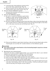
.... If the bar is more than 20" (inside dimensin of diflection guard) or less and the fixed length is still small of the rebar cutter/bender. (Fig. 18) (2) Open the guard fully by pulling the arms as shown below until the bending roller begins reverse rotation.) 20 CAUTION: G Set... or less (Fig. 20) (2) Be sure to or shorter than you desire. (2) Pull the switch trigger lightly and bend the rebar slowly. (3) When the rebar is equal to install the deflection guard when bending a rebar whose bending length and Fig. 19 the fixed length are more and return the bending roller to...
.... If the bar is more than 20" (inside dimensin of diflection guard) or less and the fixed length is still small of the rebar cutter/bender. (Fig. 18) (2) Open the guard fully by pulling the arms as shown below until the bending roller begins reverse rotation.) 20 CAUTION: G Set... or less (Fig. 20) (2) Be sure to or shorter than you desire. (2) Pull the switch trigger lightly and bend the rebar slowly. (3) When the rebar is equal to install the deflection guard when bending a rebar whose bending length and Fig. 19 the fixed length are more and return the bending roller to...


