Hitachi NR90GC Support Question
Hitachi NR90GC Support Question
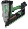
Find answers below for this question about Hitachi NR90GC - 3-1/2" Gas Powered Clipped Head Framing Nailer.Need a Hitachi NR90GC manual? We have 1 online manual for this item!
Question posted by hstancil on July 23rd, 2010
Gun Doesn't Always Fire On The First Trigger Poll.
Gun usually will fire on the 2nd or 3rd, but not always on the first.
Current Answers
Related Hitachi NR90GC Manual Pages
Service Manual - Page 5
...Code No. 753600) Grease (Code No. 317918)
5-2. next, pull the trigger to drive the nail. Specifications (1) Gas nailer
Model
NR 90GC
Driving system
Reciprocating piston type
Weight
Dimensions (Length x Height ... accessories
- After nailing once, nailing will not be possible again until the trigger is equipped with FULL SEQUENTIAL ACTUATION MECHANISM. Explanation of the Nailing Action To ...
Service Manual - Page 13
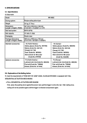
...energy in spark switch. The handle unit contains a trigger with a fuel cell and a battery in order to the center of the cylinder head through the spring.
This spring absorbs shock to the ...This is the Hitachi's first gas strip nailer and there is a nailer that of the main parts are fed from the fuel cell to the motor. Features of a pneumatic nailer except the magazine section. ...
Service Manual - Page 14
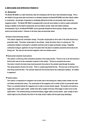
Output section
Head section (Cylinder head section)
Filter [4]
Cylinder Head [14] Spark Plug (A) [11]
Motor Spring [12] Fan [20]
Combustion chamber Chamber [24]
Motor Mount [8] Top Cover [3] Motor [6]
Cell Cover [109] Cell Lever [105]
Switch Lever (B) [114]
Cylinder Ass'y [42] Housing Ass'y [74]
Piston [39]
Battery [111]
Piston Bumper [40] Pushing Lever [64]
Trigger [98...
Service Manual - Page 15

... into the combustion chamber.
Combustion chamber
Fan [20]
Then the nailer starts operation in the
combustion chamber rotates. The Chamber Head [22] is sealed by the O-ring [36] simultaneously.
Chamber...convex portion of Chamber [24]
Fig. 4
Switch Plate [34]
Fuel cell
Trigger [98]
Cell Lever [105] Chamber [24] Trigger [98] Switch Lever (B) [114]
Fan switch
Pushing Lever [64] --- 12...
Service Manual - Page 16
...42]. The Piston [39] is depressed. Nail Fig. 6
Switch Lever (B) [114]
Switch Trigger [98]
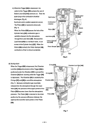
(3) During return When the Trigger [98] is depressed, the Chamber
O-ring [15]
Lock Bar [100] at the bottom... of fuel is partially
released into the atmosphere through the Lead Valve [45]. Because combustion gas is almost completed. Chamber Lock Bar [100]
Fig. 7
--- 13 ---
Then the
...
Service Manual - Page 17
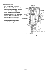
O-ring [15]
Fan [20] Trigger [98]
Pushing Lever [64]
Chamber Lock Bar [100] Fig. 8
--- 14 --- When the Fan [20] ...] and [36]
Combustion chamber
is returned from the position under the Chamber [24] to discharge gas and cool the
combustion chamber (Fig. 8). (4) Discharging and cooling
When the Trigger [98] is released, the
Chamber Lock Bar [100] is released. Thus the Chamber [24...
Service Manual - Page 18
...]
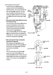
Then the convex portion of the Lever Stopper [116] is turned on . Switch Lever (B) [114]
Trigger [98]
Fig. 10 (A --- Then the nailer operates only when the Trigger [98] is not
turned on and nails
are driven by the Trigger [98] and
the end of the Chamber [24]
pushes up
the Tension Plate [113] and...
Service Manual - Page 19
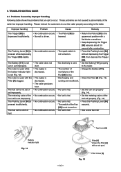
... Handling Following table shows the problems that are apt to the nailer. Press the Pushing Lever [64] without depressing the Trigger [98], then depress the Trigger [98].
Please instruct the customers to use the nailer properly according to the uppermost position with an air gun.)
Fig. 13
Filter Cover [5] No combustion occurs. No combustion occurs...
Service Manual - Page 22
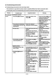
...Pushing Lever [64] cannot be pushed up. The battery indicator light lights red. Keep depressing the Trigger [98] securely until the nailing operation is deformed. Mount the O-ring [15] properly.
Remove the... (A) [60] and (B) [62] are out of fuel in the case of gas nailers The mechanism of a gas nailer to produce output is completely different from that the fuel cell is not set properly...
Service Manual - Page 23

Spark plug cable
Controller [101].
Controller connector Fig. 16 Motor wire connector
Fig. 17 --- 20 --- The wire must not be pinched when depressing the Trigger [98].
Service Manual - Page 24
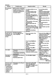
... is not set properly and return completely. The Battery [111] is normal. The wire near the Trigger [98] is deformed.
Clean spark plug (A) (Fig. 18). Return the Piston [39] to ...Low output. Keep depressing the Trigger [98] securely until the nailing operation is driven though nails are worn. Replace Internal Wire (A) [86]. Do not use the nailer at high speed. Mount each...
Service Manual - Page 29
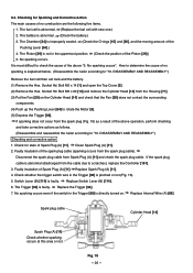
... M5 x 20 [13] and remove the Cylinder Head [14] from the Housing [71]. (3) Put the Fan [20] on .
Clean Spark Plug (A) [11]. 2. Check whether the trigger switch wire in the uppermost position. (Check the ... the Piston [39].) 5. If the spark plug cable is explained below. (Disassemble the nailer according to determine the cause of the
Pushing Lever [64].) 4. Faulty insulation of Spark...
Service Manual - Page 33

Grease application areas
Handle (B) [84]
Plunger of the fan switch
Plunger of the trigger switch
Fig. 22
--- 30 ---
Service Manual - Page 58
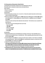
... head ...following parts that the lower end of handle (A) ass'y and handle (B) ass'y. [Tools required]
Hex. Place handle (B) ass'y on a workbench and put on handle ... length. Gently pull up handle (A) facing handle (B) (hooked side) downward. Overtightening the Hex. Trigger Spring [97] Trigger [98] Switch Lever (B) [114] Lever Stopper [116] Spring [129] (b) Reassembly Reassemble handle...
Service Manual - Page 60

... Side Plate [55]. (2) Disassembly and reassembly of Handle (A) [124], nail feeder and the related parts (Fig. 51) [Tools required]
Phillips screwdriver Roll pin puller (4 mm (0.157")) (a) Disassembly Remove the Lever Stopper [116] from the trigger of Handle (A) [124] with a hand. Remove the Nail Rail [93] with a hand. Loosen the Tapping Screw (W/Flange...
Service Manual - Page 64

... Remove the Tapping Screw (W/Flange) D4 x 14 (Black) [95] to remove the Trigger [98]. Remove the Flat Hd. Remove the Roll Pin D2.5 x 10 [99]...95] to remove the Wiring Cover [103]. Disconnect the connector of Handle (B) [84], Controller [101] and the related parts [Tools required]
Spanner Hex. Remove the Pin D2.5 [115] and Switch Lever (B) [114]. bar wrench (4 mm) Phillips screwdriver ...
Service Manual - Page 65

...]
Handle (B) [84]
Switch Mount [81]
Switch Arm [82] Spring [129]
Internal Wire (A) [86]
Hook ass'y
Prism [96]
Nylon Nut M5 [92] Nail Rail [93]
Trigger Spring [97]
Trigger [98]
Tapping
Screw
(W/Flange)
D4 x 14
Roll Pin
Controller (Black)
D2.5 x 10 [99] [101] [95]
Chamber Lock Bar [100]
Tapping Screw (W/Flange) D4 x 14...
Service Manual - Page 66

Internal Wire (A) [86]
Roll Pin D2.5 x 10 [99]
Split Plunger
Trigger [98] Fig. 55
--- 63 --- Do not damage the plunger of Internal Wire (A) [86] (Fig. 56). Do not apply tension to Handle (B) [84] then hang the ... be followed in Fig. 56. Note the following points. Be careful of the split direction of the Roll Pin D2.5 x 10 [99] when mounting the Trigger [98] and Internal Wire (A) [86].
Service Manual - Page 67

... [97] Lock Bar Spring [102]
Switch Mount [81] Switch Arm [82]
Trigger [98] Prism [96]
Hook ass'y
Hook ass'y Nylon Nut M5 [92]
Do not apply tension. Tapping Screw (W/Flange) D4 x 14 (Black) [95]
Hex. Bolt M5 x ... lead wire at the top. Handle (B) [84]
Perform wiring so that no lead wire is placed on this rib and no pinching occurs by the Trigger [98] operation.
Service Manual - Page 72
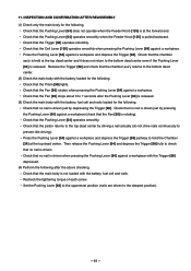
... the Pushing Lever [64] against a workpiece. Then release the Pushing Lever [64] and depress the Trigger [98] fully to hold the Chamber [24] at the top dead center. Recheck the tightening torque ...to prevent idle driving). Check that the piston returns to the top dead center by depressing the Trigger [98]. Check that no nail is rotating). Check that the Pushing Lever [64] operates ...
Similar Questions

Nr90gc Has Gun Nailer
My gun has been cleaned but I fire one nail and it won't fire another one until it has done its cycl...
My gun has been cleaned but I fire one nail and it won't fire another one until it has done its cycl...
(Posted by mwraight 3 years ago)

My Hitachi Nt65ga Nail Gun Will Not Fire Nails No Action From Trigger
My gun has worked great except not it will not do anything when the trigger is pulled it will give a...
My gun has worked great except not it will not do anything when the trigger is pulled it will give a...
(Posted by floyda58 6 years ago)

No Spark
Hi Could you tell me what the problem may be. My gun is not sending power to the spark plug
Hi Could you tell me what the problem may be. My gun is not sending power to the spark plug
(Posted by roymackarel 11 years ago)

Hitachi Framing Gun
hi my battery has water damage and i need a new one but can not seem to find one for sale anywhere i...
hi my battery has water damage and i need a new one but can not seem to find one for sale anywhere i...
(Posted by nathan1187 11 years ago)

Nail Gun
nail gun wont keep firing nails while trigger is held only fires one nail then i have to release tri...
nail gun wont keep firing nails while trigger is held only fires one nail then i have to release tri...
(Posted by rcbender 12 years ago)