Instruction Manual
Page 10
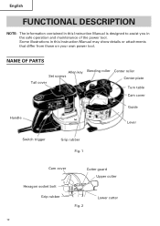
English FUNCTIONAL DESCRIPTION NOTE: The information contained in the safe operation and maintenance of the power tool. NAME OF PARTS Allen key Set screws Tail cover Bending roller Center roller Center plate Turn table Cam cover Handle Guide Lever Switch trigger Grip rubber Fig. 1 Cam cover Cutter guard Upper cutter Hexagon socket bolt Grip rubber Fig. 2 Lower cutter 10 Some illustrations in this Instruction Manual is designed to assist you in this Instruction Manual may show details or attachments that differ from those on your own power tool.
English FUNCTIONAL DESCRIPTION NOTE: The information contained in the safe operation and maintenance of the power tool. NAME OF PARTS Allen key Set screws Tail cover Bending roller Center roller Center plate Turn table Cam cover Handle Guide Lever Switch trigger Grip rubber Fig. 1 Cam cover Cutter guard Upper cutter Hexagon socket bolt Grip rubber Fig. 2 Lower cutter 10 Some illustrations in this Instruction Manual is designed to assist you in this Instruction Manual may show details or attachments that differ from those on your own power tool.
Instruction Manual
Page 18
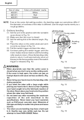
... position with the turntable up as shown in Fig. 14. (2) Make sure that the cutter cover is closed . (3) Set the setting dial at the same dial setting position, the bending angle can jam on the center plate and set it correctly as shown in Fig. 14. (5) Pull the switch trigger... and bent the rebar. (6) Continue pulling the switch trigger untill the motor makes reverse rotation and the bending roller starts to return. (Once the bending roller starts to return, it will automatically...
... position with the turntable up as shown in Fig. 14. (2) Make sure that the cutter cover is closed . (3) Set the setting dial at the same dial setting position, the bending angle can jam on the center plate and set it correctly as shown in Fig. 14. (5) Pull the switch trigger... and bent the rebar. (6) Continue pulling the switch trigger untill the motor makes reverse rotation and the bending roller starts to return. (Once the bending roller starts to return, it will automatically...
Instruction Manual
Page 19
...rebar cutter/bender in case a rebar splinters into fragments and scatter dangerously. (Fig. 14) ⅜ Place the rebar on a stable spots such as floor, ground, etc. ⅜ Begin operation only after placing it on the center... bending length is 8" (200 mm). Install the deflection guard to the VB16Y for operation with the bending length of a rebar 20" (inside dimension of the deflection guard) or less to the deflection...bending length is not long enough, the rebar can come off during bending operation, or it can come loose from the bending roller while bending causing it to use the...
...rebar cutter/bender in case a rebar splinters into fragments and scatter dangerously. (Fig. 14) ⅜ Place the rebar on a stable spots such as floor, ground, etc. ⅜ Begin operation only after placing it on the center... bending length is 8" (200 mm). Install the deflection guard to the VB16Y for operation with the bending length of a rebar 20" (inside dimension of the deflection guard) or less to the deflection...bending length is not long enough, the rebar can come off during bending operation, or it can come loose from the bending roller while bending causing it to use the...
Instruction Manual
Page 21
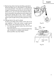
...you can sometimes get caught in place A hole is bolted to its own flexure. Removing rebar during cutting operation. (Fig. 22) 8. This hole will prove very convenient when the unit is provided at the center of the unit to fix and stabilize it gets caught during bending operation When bending out... at a low speed in "bending by eye measurement", the rebar can return the bending roller to the home position by pulling the switch again ...
...you can sometimes get caught in place A hole is bolted to its own flexure. Removing rebar during cutting operation. (Fig. 22) 8. This hole will prove very convenient when the unit is provided at the center of the unit to fix and stabilize it gets caught during bending operation When bending out... at a low speed in "bending by eye measurement", the rebar can return the bending roller to the home position by pulling the switch again ...
Instruction Manual
Page 23
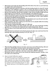
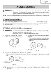
...HITACHI. Fig. 25 2" (50 mm) Fig. 26 (3) Center Roller (D 38) Set (Fig. 26)(Code No. 321445) * This is used when the bending diameter of cutters 1 (attached to unit) (2) One set (D50). NOTE: Accessories are mentioned in diameter) using the center roller set (D38) and center roller set of a rebar... ACCESSORIES.......sold separately WARNING: Do not bend the rebar with #5 (5/8" in this Instruction Manual. Otherwise, there is a fear that the rebar may snap. (1) Cutter (Fig. 25)(Code No. 319706) * One set containing two pieces (2) Center Roller (D 50) Set (Fig. 26)(Code No....
...HITACHI. Fig. 25 2" (50 mm) Fig. 26 (3) Center Roller (D 38) Set (Fig. 26)(Code No. 321445) * This is used when the bending diameter of cutters 1 (attached to unit) (2) One set (D50). NOTE: Accessories are mentioned in diameter) using the center roller set (D38) and center roller set of a rebar... ACCESSORIES.......sold separately WARNING: Do not bend the rebar with #5 (5/8" in this Instruction Manual. Otherwise, there is a fear that the rebar may snap. (1) Cutter (Fig. 25)(Code No. 319706) * One set containing two pieces (2) Center Roller (D 50) Set (Fig. 26)(Code No....
