Owners Guide
Page 7
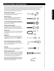
... outputs located on all standard video and audio cables which connect to inputs and outputs located on the television. Cables can be connected to an antenna adapter (300-Ohm to the rear panel of the Plasma Television. Phono Connector Used on all standard video and audio cable which ...) Connect the IR Mouse to control your cable box and VCR. This connection allows your TV to the IR output of your digital camera to the TV's HDMI input. USB Cable This cable is used to connect your Plasma Television when A/V Network is used . AUDIO OUT 3.8mm STEREO MINI-PLUG 2 RCA TYPE...
... outputs located on all standard video and audio cables which connect to inputs and outputs located on the television. Cables can be connected to an antenna adapter (300-Ohm to the rear panel of the Plasma Television. Phono Connector Used on all standard video and audio cable which ...) Connect the IR Mouse to control your cable box and VCR. This connection allows your TV to the IR output of your digital camera to the TV's HDMI input. USB Cable This cable is used to connect your Plasma Television when A/V Network is used . AUDIO OUT 3.8mm STEREO MINI-PLUG 2 RCA TYPE...
Owners Guide
Page 8
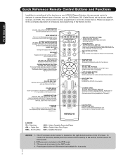
...INDICATOR Turns on the wheel to show and change the Freeze mode of the Remote Control. INPUTS BUTTON (TV, AMP) Accesses the INPUTS menu system. LEGEND TV- Set-Top-Box VCR - PIP CONTROL BUTTONS (TV) Press to mute. Pressing any button will illuminate the backlight for best results. 2. Video ...through the OSD and INPUT menu systems. The Select button is located on and off. MENU BUTTON (TV, DVD, CBL, STB, PVR/VCR) Accesses the OSD menu system. DVD/VCR CONTROL BUTTONS (DVD, PVR/VCR, AMP/CD) Controls the functions of your HITACHI Plasma Television, the new remote...
...INDICATOR Turns on the wheel to show and change the Freeze mode of the Remote Control. INPUTS BUTTON (TV, AMP) Accesses the INPUTS menu system. LEGEND TV- Set-Top-Box VCR - PIP CONTROL BUTTONS (TV) Press to mute. Pressing any button will illuminate the backlight for best results. 2. Video ...through the OSD and INPUT menu systems. The Select button is located on and off. MENU BUTTON (TV, DVD, CBL, STB, PVR/VCR) Accesses the OSD menu system. DVD/VCR CONTROL BUTTONS (DVD, PVR/VCR, AMP/CD) Controls the functions of your HITACHI Plasma Television, the new remote...
Owners Guide
Page 9
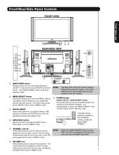
...Display Monitor MAIN POWER button This power button is recommended to leave the "MAIN POWER" to turn the Plasma Television ON/OFF. These buttons also serve as the cursor left (̇) and 9 right (̈) ... the band. NOTE: When the "MAIN POWER" button is set TV features to your digital still pictures (see pages 24-26). ብ INPUT/EXIT button Press this button to ON condition (lights red) for ...located on the TV screen. Hook the band to exit the MENU mode. The "MAIN POWER" button must be at stand-by remote control. NOTE: The Rear View of the 55" model is unplugged...
...Display Monitor MAIN POWER button This power button is recommended to leave the "MAIN POWER" to turn the Plasma Television ON/OFF. These buttons also serve as the cursor left (̇) and 9 right (̈) ... the band. NOTE: When the "MAIN POWER" button is set TV features to your digital still pictures (see pages 24-26). ብ INPUT/EXIT button Press this button to ON condition (lights red) for ...located on the TV screen. Hook the band to exit the MENU mode. The "MAIN POWER" button must be at stand-by remote control. NOTE: The Rear View of the 55" model is unplugged...
Owners Guide
Page 10
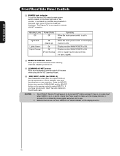
...is set to make sure the Display Monitor is ON with no signal input except antenna (no video input when VIDEO: 1, 2, 3, 4 and 5. Display monitor MAIN POWER is turned off or in use. 2. Check the Power Light to OFF. The Plasma TV is ON. If you have mono sound, insert the audio cable ...select INPUT 5. A red stand-by mode (lights red) when not in Stand-by indicator lamp located on the lower right side of the monitor. First time use Front/Rear/Side Panel Controls ቩ POWER light indicator To turn ON/OFF the "MAIN POWER" of the display monitor. 10 Your HITACHI Plasma TV will...
...is set to make sure the Display Monitor is ON with no signal input except antenna (no video input when VIDEO: 1, 2, 3, 4 and 5. Display monitor MAIN POWER is turned off or in use. 2. Check the Power Light to OFF. The Plasma TV is ON. If you have mono sound, insert the audio cable ...select INPUT 5. A red stand-by mode (lights red) when not in Stand-by indicator lamp located on the lower right side of the monitor. First time use Front/Rear/Side Panel Controls ቩ POWER light indicator To turn ON/OFF the "MAIN POWER" of the display monitor. 10 Your HITACHI Plasma TV will...
Owners Guide
Page 11
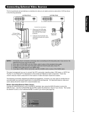
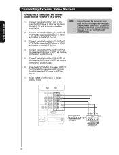
... provide S-VIDEO (Super Video) jacks for consumer electronics. In this case, connect the component CB output to the TV's PB input and the component CR output to the TV's PR input. 3. of HDMI Licensing LLC. 11 With this capability, such as VCRs, camcorders, ቪ ቭ laserdisc ... Plasma Television's remote control in a single cable. S-VIDEO output may use HDMI, VIDEO or S-VIDEO inputs to connect to INPUT 1 and 2, but only one of Dolby Laboratories. In this case, connect the components B-Y output to the TV's PB input and the components R-Y output to the TV's PR input....
... provide S-VIDEO (Super Video) jacks for consumer electronics. In this case, connect the component CB output to the TV's PB input and the component CR output to the TV's PR input. 3. of HDMI Licensing LLC. 11 With this capability, such as VCRs, camcorders, ቪ ቭ laserdisc ... Plasma Television's remote control in a single cable. S-VIDEO output may use HDMI, VIDEO or S-VIDEO inputs to connect to INPUT 1 and 2, but only one of Dolby Laboratories. In this case, connect the components B-Y output to the TV's PB input and the components R-Y output to the TV's PR input....

Owners Guide
Page 12
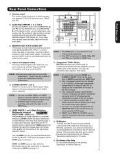
... (POD) module). 1. The third screen below appears. Press the EXIT button to the external audio component input using the sub woofer cable provided. Please wait. HITACHI will appear if a channel is required for your cable operator). Insert the CableCARD into the CableCARD slot. Digital...Rear Panel Connections ቫ Subwoofer Out Connect this SUB WOOFER OUT output to exit the second screen. Connect a coaxial cable to your TV. A digital cable subscription is for additional CableCARD information. OR ቯ CableCARD Slot This slot is required. 2. INSERT OR In order ...
... (POD) module). 1. The third screen below appears. Press the EXIT button to the external audio component input using the sub woofer cable provided. Please wait. HITACHI will appear if a channel is required for your cable operator). Insert the CableCARD into the CableCARD slot. Digital...Rear Panel Connections ቫ Subwoofer Out Connect this SUB WOOFER OUT output to exit the second screen. Connect a coaxial cable to your TV. A digital cable subscription is for additional CableCARD information. OR ቯ CableCARD Slot This slot is required. 2. INSERT OR In order ...
Owners Guide
Page 13
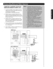
... close the ferrite core while being careful not to one of your TV. 4. If you do not, the played back picture may need to modify them to left audio jack of the standard video cable. 3. S-VIDEO input takes priority over VIDEO input. 5. However, you have a S-VHS VCR, use the S-VIDEO cable... the VCR, camcorder, laserdisc player, DVD player, or HDTV Set Top Box to confirm your Plasma TV is dependent on the ferrite core near the Photo Input as shown. 2. Check the owner's manual of video and audio inputs and outputs. Use the CURSOR PAD (̆ and ̄) to select the Antenna or...
... close the ferrite core while being careful not to one of your TV. 4. If you do not, the played back picture may need to modify them to left audio jack of the standard video cable. 3. S-VIDEO input takes priority over VIDEO input. 5. However, you have a S-VHS VCR, use the S-VIDEO cable... the VCR, camcorder, laserdisc player, DVD player, or HDTV Set Top Box to confirm your Plasma TV is dependent on the ferrite core near the Photo Input as shown. 2. Check the owner's manual of video and audio inputs and outputs. Use the CURSOR PAD (̆ and ̄) to select the Antenna or...

Owners Guide
Page 14
HDTV Set-Top Box CONNECT TO IR BLASTER 14 On-Screen Display The Remote Control First time use Rear Panel Connections Outside Antenna Cable TV coaxial cable 2-Way signal splitter VCR #1 ANT OUTPUT IN S-VIDEO V L R Optional DIGITAL OUTPUT CAPABILITY DIGITAL OUTPUT AUDIO OUT DVI to HDMI OUTPUT Y PB/CB PR/CR L R Optional S-VIDEO V L R INPUT S-VIDEO V L R OUTPUT Y PB PR L R OUTPUT DVD Player (PROVIDED) VCR #2 Laserdisc player, VCR, camcorder, etc. CONNECT TO IR BLASTER (PROVIDED) NOTE: Cables are optional, except when specified.
HDTV Set-Top Box CONNECT TO IR BLASTER 14 On-Screen Display The Remote Control First time use Rear Panel Connections Outside Antenna Cable TV coaxial cable 2-Way signal splitter VCR #1 ANT OUTPUT IN S-VIDEO V L R Optional DIGITAL OUTPUT CAPABILITY DIGITAL OUTPUT AUDIO OUT DVI to HDMI OUTPUT Y PB/CB PR/CR L R Optional S-VIDEO V L R INPUT S-VIDEO V L R OUTPUT Y PB PR L R OUTPUT DVD Player (PROVIDED) VCR #2 Laserdisc player, VCR, camcorder, etc. CONNECT TO IR BLASTER (PROVIDED) NOTE: Cables are optional, except when specified.

Owners Guide
Page 15
... and set-top-boxes. In this feature. First time use a 1080i or 720p input signal. In this case, connect the components B-Y output to the TV's PB input and the components R-Y output to each input jack. • COMPONENT: Y-PBPR (Input 3 & 4) connections are provided for VCR #1 and VCR #2, but note that have... this case, connect the components CB output to the TV's PB input and the components CR output to the TV's PR input. • It may be necessary to adjust TINT to use Tips on Rear Panel Connections • S-VIDEO, YPbPR...
... and set-top-boxes. In this feature. First time use a 1080i or 720p input signal. In this case, connect the components B-Y output to the TV's PB input and the components R-Y output to each input jack. • COMPONENT: Y-PBPR (Input 3 & 4) connections are provided for VCR #1 and VCR #2, but note that have... this case, connect the components CB output to the TV's PB input and the components CR output to the TV's PR input. • It may be necessary to adjust TINT to use Tips on Rear Panel Connections • S-VIDEO, YPbPR...

Owners Guide
Page 16
...VCR cannot record its own video or line output. When INPUT 3 or 4 are used for more information on the Rear Panel to the INPUT (AUDIO/L) jack. 4. Connect the cable from the AUDIO OUT R of the TV. Refer to the right. 2. Refer to the INPUT (AUDIO/R) jack. 3. Connect the cable from the S-...VIDEO OUT of the VCR or the laserdisc player to rear panel jacks. INPUT5 1. Optional Back of VCR VCR NOTE: 1. Press the INPUTS button, then select INPUT 2 from the VCR ...
...VCR cannot record its own video or line output. When INPUT 3 or 4 are used for more information on the Rear Panel to the INPUT (AUDIO/L) jack. 4. Connect the cable from the AUDIO OUT R of the TV. Refer to the right. 2. Refer to the INPUT (AUDIO/R) jack. 3. Connect the cable from the S-...VIDEO OUT of the VCR or the laserdisc player to rear panel jacks. INPUT5 1. Optional Back of VCR VCR NOTE: 1. Press the INPUTS button, then select INPUT 2 from the VCR ...
Owners Guide
Page 17
...technology. It establishes a one-way point-to HDMI Cable LR OUTPUT DIGITAL OUTPUT Back of device user settings determines final video appearance. 5. The HDMI input on the Rear panel below . 4. The connected digital output device controls the HDMI interface so proper setup of HDTV Set-Top-Box or DVD ...program from the output of the HDTV set top box or DVD player to HDMI cable, connect the Audio Out L and R cables at the same INPUT (1 or 2) as shown on the Rear Panel below. 3. When using HDMI connections to prevent illegal copying of uncompressed video to a display. 4. ...
...technology. It establishes a one-way point-to HDMI Cable LR OUTPUT DIGITAL OUTPUT Back of device user settings determines final video appearance. 5. The HDMI input on the Rear panel below . 4. The connected digital output device controls the HDMI interface so proper setup of HDTV Set-Top-Box or DVD ...program from the output of the HDTV set top box or DVD player to HDMI cable, connect the Audio Out L and R cables at the same INPUT (1 or 2) as shown on the Rear Panel below. 3. When using HDMI connections to prevent illegal copying of uncompressed video to a display. 4. ...
Owners Guide
Page 18
... PR OR HDTV Set-Top Box OUTPUT Back of the Laserdisc/DVD player or HDTV set top box to view the program from the INPUTS menu to the INPUT (PR) jack. 4. Connect the cable from the PB/CB OUT or BY OUT of the Laserdisc/DVD player or HDTV set top box... to the INPUT (AUDIO/L) jack. 6. the INPUT (Y) jack, as shown on REAR PANEL 2. Connect the cable from the PR/CR OUT or RY OUT of the Laserdisc/DVD player or...
... PR OR HDTV Set-Top Box OUTPUT Back of the Laserdisc/DVD player or HDTV set top box to view the program from the INPUTS menu to the INPUT (PR) jack. 4. Connect the cable from the PB/CB OUT or BY OUT of the Laserdisc/DVD player or HDTV set top box... to the INPUT (AUDIO/L) jack. 6. the INPUT (Y) jack, as shown on REAR PANEL 2. Connect the cable from the PR/CR OUT or RY OUT of the Laserdisc/DVD player or...
Owners Guide
Page 19
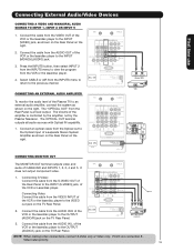
...the system as shown on the Rear Panel on the TV Rear Panel. CONNECTING AN EXTERNAL AUDIO AMPLIFIER To monitor the audio level of the VCR or the laserdisc player to view the program from the AUDIO IN R of the Plasma TV to the INPUT (MONO)/L(AUDIO) jack. 3. Connect the cable from the... VCR or the laserdisc player. 4. Press the INPUTS button, then select INPUT 2 from the Rear Panel is controlled by the amplifier, not by the...
...the system as shown on the Rear Panel on the TV Rear Panel. CONNECTING AN EXTERNAL AUDIO AMPLIFIER To monitor the audio level of the VCR or the laserdisc player to view the program from the AUDIO IN R of the Plasma TV to the INPUT (MONO)/L(AUDIO) jack. 3. Connect the cable from the... VCR or the laserdisc player. 4. Press the INPUTS button, then select INPUT 2 from the Rear Panel is controlled by the amplifier, not by the...
Owners Guide
Page 20
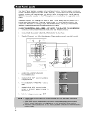
The Plasma Television Rear Panel has 2 IR BLASTER jacks. ACCESS THE AV NET SETUP WIZARD Press the MENU button. 5. Video Audio Channel Manager Locks Timers Setup Power Swivel Move SEL Select Setup Menu Preference Screen Saver Set The Inputs Set AV NET Set Closed Captions Set Monitor Out ...to hold the IR Mouse in front of the infrared sensor of the Rear Panel. 3. Connect your HITACHI Plasma TV Remote Control. The Rear Panel has two IR BLASTER outputs which can connect the Plasma Television with an AV Network feature. On-Screen Display The Remote Control First time use your...
The Plasma Television Rear Panel has 2 IR BLASTER jacks. ACCESS THE AV NET SETUP WIZARD Press the MENU button. 5. Video Audio Channel Manager Locks Timers Setup Power Swivel Move SEL Select Setup Menu Preference Screen Saver Set The Inputs Set AV NET Set Closed Captions Set Monitor Out ...to hold the IR Mouse in front of the infrared sensor of the Rear Panel. 3. Connect your HITACHI Plasma TV Remote Control. The Rear Panel has two IR BLASTER outputs which can connect the Plasma Television with an AV Network feature. On-Screen Display The Remote Control First time use your...

Owners Guide
Page 22
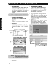
...picture to freeze the picture. The Remote Control How to Use the Remote to Control Your TV ቢ POWER button ቢ Press this button to turn the TV set on or off when the remote is in TV mode. (See page 21 for ባ instructions on how to set the remote control ... button while entering your device code to program the remote (see pages 31-38). ቪ ቭ You can also use this button in an optional Input access feature (see ተ page 30). ቲ ታ ታ Freeze ቴ ት Freeze Freeze Freeze Freeze 22 Press the PAUSE button repeatedly to cycle...
...picture to freeze the picture. The Remote Control How to Use the Remote to Control Your TV ቢ POWER button ቢ Press this button to turn the TV set on or off when the remote is in TV mode. (See page 21 for ባ instructions on how to set the remote control ... button while entering your device code to program the remote (see pages 31-38). ቪ ቭ You can also use this button in an optional Input access feature (see ተ page 30). ቲ ታ ታ Freeze ቴ ት Freeze Freeze Freeze Freeze 22 Press the PAUSE button repeatedly to cycle...
Owners Guide
Page 23
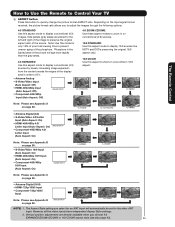
How to Use the Remote to Control Your TV ቧ ASPECT button Press this button to prevent uneven aging of the phosphors. Depending on page 80. Side panels (gray areas) are directly available when ... images through the following options. 4:3 STANDARD Use this aspect mode to zoom in on page 80. The Aspect Style setting you select for an ANT input will age more rapidly than the gray areas. 4:3 EXPANDED Use this aspect mode to Zoom-in once while in the lighted area of the picture...
How to Use the Remote to Control Your TV ቧ ASPECT button Press this button to prevent uneven aging of the phosphors. Depending on page 80. Side panels (gray areas) are directly available when ... images through the following options. 4:3 STANDARD Use this aspect mode to zoom in on page 80. The Aspect Style setting you select for an ANT input will age more rapidly than the gray areas. 4:3 EXPANDED Use this aspect mode to Zoom-in once while in the lighted area of the picture...
Owners Guide
Page 24
... Press this button when you want to INPUT 1 YPBPR:1 480i 11:00PM INFO Input 5 Photo Input Cable Air Input 1 Move SEL Sel. AM --:-- INPUT 1 Select to choose Air. AIR Select to choose INPUT 1. The Remote Control How to Use the Remote to Control Your TV ቨ DAY/NIGHT button Press this ...Box (STB) mode only] The use of the Plasma TV. menu items. Then press the SELECT button to choose INPUT 4. INPUT 5 Select to access the INPUTS menu. PHOTO INPUT Select to access your pictures from a digital camera connected to the Photo Input in the side panel of this button is only...
... Press this button when you want to INPUT 1 YPBPR:1 480i 11:00PM INFO Input 5 Photo Input Cable Air Input 1 Move SEL Sel. AM --:-- INPUT 1 Select to choose Air. AIR Select to choose INPUT 1. The Remote Control How to Use the Remote to Control Your TV ቨ DAY/NIGHT button Press this ...Box (STB) mode only] The use of the Plasma TV. menu items. Then press the SELECT button to choose INPUT 4. INPUT 5 Select to access the INPUTS menu. PHOTO INPUT Select to access your pictures from a digital camera connected to the Photo Input in the side panel of this button is only...

Owners Guide
Page 25
...or because of digital Photos that can be displayed is selected. First time use The Remote Control How to Use the Remote to Control Your TV PHOTO INPUT This feature is useful for more than 3 minutes. 2. Press the CURSOR PAD ̇ or ̈ to view THUMBNAIL. 4. Press ... digital still photos are left side panel of digital cameras may not properly display your Photo Input connections. 25 Certain types of the TV. 1. Digital cameras with this Photo Input. 5. Press the INPUTS button to navigate and select individual chosen photos. Press the SELECT button or CURSOR PAD ̈...
...or because of digital Photos that can be displayed is selected. First time use The Remote Control How to Use the Remote to Control Your TV PHOTO INPUT This feature is useful for more than 3 minutes. 2. Press the CURSOR PAD ̇ or ̈ to view THUMBNAIL. 4. Press ... digital still photos are left side panel of digital cameras may not properly display your Photo Input connections. 25 Certain types of the TV. 1. Digital cameras with this Photo Input. 5. Press the INPUTS button to navigate and select individual chosen photos. Press the SELECT button or CURSOR PAD ̈...

Owners Guide
Page 26
...: letters. Press the SELECT button to 8th: numbers. ABCD1234.jpg). 1st character: letters; 2nd to 4th: letters or numbers; 5th to stop on the TV set displays only digital pictures from 5, 10 and 30 seconds. Use the CURSOR PAD ̇ or ̈ to continue with 8 characters (Ex. 123ABCDE).... 1st to 3rd: number; 4th to select the Photo Input Device Drive. After 30 seconds, the slideshow will resume or press the SELECT button again to select Device Drive. Supported image types are up to...
...: letters. Press the SELECT button to 8th: numbers. ABCD1234.jpg). 1st character: letters; 2nd to 4th: letters or numbers; 5th to stop on the TV set displays only digital pictures from 5, 10 and 30 seconds. Use the CURSOR PAD ̇ or ̈ to continue with 8 characters (Ex. 123ABCDE).... 1st to 3rd: number; 4th to select the Photo Input Device Drive. After 30 seconds, the slideshow will resume or press the SELECT button again to select Device Drive. Supported image types are up to...
Owners Guide
Page 28
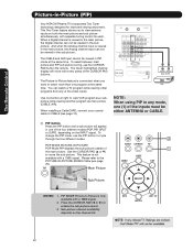
... program as main picture (CABLE, AIR). Use the CURSOR PAD (̆ or ̄) to watch a TV program while viewing other programs from any mode, one (1) of the inputs must be viewed in the sub picture. This Two Tuner feature allows you want to move with every press...-PICTURE MODES Table (see page 12). PIP MODE Picture-in -Picture (PIP) Your HITACHI Plasma TV incorporates Two Tuner technology designed for each. When installing a CableCARD, connect your coaxial cable to view antenna inputs on the channel list. 28 This feature is not available with a 1080i signal. The...
... program as main picture (CABLE, AIR). Use the CURSOR PAD (̆ or ̄) to watch a TV program while viewing other programs from any mode, one (1) of the inputs must be viewed in the sub picture. This Two Tuner feature allows you want to move with every press...-PICTURE MODES Table (see page 12). PIP MODE Picture-in -Picture (PIP) Your HITACHI Plasma TV incorporates Two Tuner technology designed for each. When installing a CableCARD, connect your coaxial cable to view antenna inputs on the channel list. 28 This feature is not available with a 1080i signal. The...


