Owners Guide
Page 3
...specified by the manufacturer. 17. A polarized plug has two blades with one wider than the other apparatus (including amplifiers) that the cable ground shall be located in accordance with the apparatus. When a cart is grounded so as video games, stock market quotations, computer ...Electric Code, ANSI/NFPA No. 70-1984, provides information with the cart, stand, tripod, bracket, or table specified by your HITACHI Factory Warranty. Use only with respect to grounding electrodes and requirements for the mast and supporting structure, grounding of the lead-in any...
...specified by the manufacturer. 17. A polarized plug has two blades with one wider than the other apparatus (including amplifiers) that the cable ground shall be located in accordance with the apparatus. When a cart is grounded so as video games, stock market quotations, computer ...Electric Code, ANSI/NFPA No. 70-1984, provides information with the cart, stand, tripod, bracket, or table specified by your HITACHI Factory Warranty. Use only with respect to grounding electrodes and requirements for the mast and supporting structure, grounding of the lead-in any...
Owners Guide
Page 4
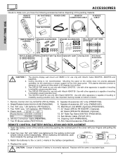
...PIP ACCESDSAY/NIGHT SWAP PIP MODE 3. Ceiling mounting is not recommended. See important marking located on tab to remove back cover. Replace with Hitachi model 32HDT55, 42HDT55 and 50HDT55. WALL MOUNT UNIT WM50 (OPTIONAL) A/V NET CH + SELECT VOL - CH - CAUTION: 1. 2. 3. 4. 5. ... incorrectly replaced. This SPD32 PDP stand for use only with Hitachi 42HDT55 Use with Hitachi 32HDT55. Remote Control Unit CLU-5726TSI (P# HL01826). 2. AVC Stand Accessories (P#QJ01081). Two IR Mouse cables (P# EY01641). 8. When replacing old batteries, push them towards...
...PIP ACCESDSAY/NIGHT SWAP PIP MODE 3. Ceiling mounting is not recommended. See important marking located on tab to remove back cover. Replace with Hitachi model 32HDT55, 42HDT55 and 50HDT55. WALL MOUNT UNIT WM50 (OPTIONAL) A/V NET CH + SELECT VOL - CH - CAUTION: 1. 2. 3. 4. 5. ... incorrectly replaced. This SPD32 PDP stand for use only with Hitachi 42HDT55 Use with Hitachi 32HDT55. Remote Control Unit CLU-5726TSI (P# HL01826). 2. AVC Stand Accessories (P#QJ01081). Two IR Mouse cables (P# EY01641). 8. When replacing old batteries, push them towards...
Owners Guide
Page 6
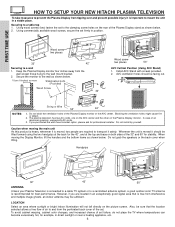
FIRST TIME USE HOW TO SETUP YOUR NEW HITACHI PLASMA TELEVISION To take measures to prevent the Plasma Display from tipping over and prevent possible injury it safely. Keep the Plasma Display monitor four ... the wall mount bracket. 2. Secure the monitor to and from interference and multiple image ghosts, an indoor antenna may be sure that is connected to a cable TV system or to a table-top 1. Install AVC Stand with screws provided. 2. AVC ventilation holes should be facing out. VOL+ CH- Do not block the...
FIRST TIME USE HOW TO SETUP YOUR NEW HITACHI PLASMA TELEVISION To take measures to prevent the Plasma Display from tipping over and prevent possible injury it safely. Keep the Plasma Display monitor four ... the wall mount bracket. 2. Secure the monitor to and from interference and multiple image ghosts, an indoor antenna may be sure that is connected to a cable TV system or to a table-top 1. Install AVC Stand with screws provided. 2. AVC ventilation holes should be facing out. VOL+ CH- Do not block the...

Owners Guide
Page 8
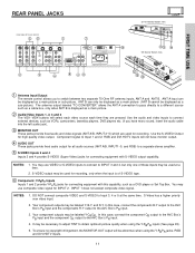
...store for the antenna mixer. 8 To outdoor VHF or UHF antenna To UHF antenna ANT A/ANT B To outdoor antenna or CATV system Antenna Mixer Cables can be made with an S-Video feature in front of the corresponding IR window of common connectors. ANTENNA CONNECTIONS TO REAR JACK PANEL VHF (75...-Ohm) antenna/CATV (Cable TV) When using a 300-Ohm twin lead from external audio out to the ANT B terminal. Phono Connector Used on the rear jack panel and...
...store for the antenna mixer. 8 To outdoor VHF or UHF antenna To UHF antenna ANT A/ANT B To outdoor antenna or CATV system Antenna Mixer Cables can be made with an S-Video feature in front of the corresponding IR window of common connectors. ANTENNA CONNECTIONS TO REAR JACK PANEL VHF (75...-Ohm) antenna/CATV (Cable TV) When using a 300-Ohm twin lead from external audio out to the ANT B terminal. Phono Connector Used on the rear jack panel and...

Owners Guide
Page 10
... illuminate (lower left for remote on the display monitor is ON, and the AVC Center is OFF. The PDP is now ready for 50"). Your HITACHI Plasma TV will only turn the monitor ON, press the main power switch located on the remote control button and VIDEO: 5 appears in use. signal... if the "MAIN POWER" of the display monitor is turned off the internal speakers (see page 48) if you have mono sound, insert the audio cable into the left for a quick hook-up from a camcorder or VCR to the head-phones only. ቫ LEARNING AV NET Sensor Point your equipment's remote...
... illuminate (lower left for remote on the display monitor is ON, and the AVC Center is OFF. The PDP is now ready for 50"). Your HITACHI Plasma TV will only turn the monitor ON, press the main power switch located on the remote control button and VIDEO: 5 appears in use. signal... if the "MAIN POWER" of the display monitor is turned off the internal speakers (see page 48) if you have mono sound, insert the audio cable into the left for a quick hook-up from a camcorder or VCR to the head-phones only. ቫ LEARNING AV NET Sensor Point your equipment's remote...
Owners Guide
Page 11
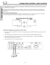
...: 1. In this case, connect the component CB output to the AVC Box's PB input and the component CR output to a different source such as a cable box, only when ANT B is of S-VIDEO type. ቧ Component: Y-PBPR Inputs Inputs 1 and 2 provide Y-PBPR jacks for connecting equipment with this...with S-VIDEO output capability. You may be necessary to adjust TINT to Input 3, 4 or 5 at a time. 2. Your component outputs may use HITACHI specified cable. ANT B can be abnormal, when using the Y-PBPR inputs (See page 45). 5. DO NOT connect composite VIDEO and S-VIDEO to obtain optimum ...
...: 1. In this case, connect the component CB output to the AVC Box's PB input and the component CR output to a different source such as a cable box, only when ANT B is of S-VIDEO type. ቧ Component: Y-PBPR Inputs Inputs 1 and 2 provide Y-PBPR jacks for connecting equipment with this...with S-VIDEO output capability. You may be necessary to adjust TINT to Input 3, 4 or 5 at a time. 2. Your component outputs may use HITACHI specified cable. ANT B can be abnormal, when using the Y-PBPR inputs (See page 45). 5. DO NOT connect composite VIDEO and S-VIDEO to obtain optimum ...

Owners Guide
Page 12
...input for RGB input (if you to INPUT 1. DVI is recommended to use a 1080i or 720p input signal. ቫ To Monitor Connect the Monitor Connection Cable to the AVC center's "TO MONITOR" connector, and to the display monitor's "FROM AVC" connector. ቭ IR Blaster This jack provides IR output ...using a Set-Top-Box, it is INPUT 1 and has priority over component input. This connection will allow you have mono sound, insert the audio cable into the left audio jack). ቪ DVI - Digital Input Use this SUB WOOFER OUT output to your external devices with digital output capability, such ...
...input for RGB input (if you to INPUT 1. DVI is recommended to use a 1080i or 720p input signal. ቫ To Monitor Connect the Monitor Connection Cable to the AVC center's "TO MONITOR" connector, and to the display monitor's "FROM AVC" connector. ቭ IR Blaster This jack provides IR output ...using a Set-Top-Box, it is INPUT 1 and has priority over component input. This connection will allow you have mono sound, insert the audio cable into the left audio jack). ቪ DVI - Digital Input Use this SUB WOOFER OUT output to your external devices with digital output capability, such ...
Owners Guide
Page 13
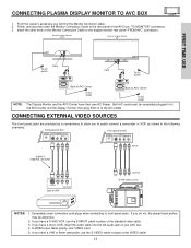
...the following examples: Front panel of AVC Front panel of SRS Labs, Inc. If you have a S-VHS VCR, use HITACHI specified cable. Firmly, and securely insert the Monitor Connection Cable to the AVC Center and the display monitor, then plug them in place of your AVC box. 4. Back of Display ...Monitor 32/42" Back of the AVC box "TO MONITOR" connectors. 3. If you have a VHS or 8mm camcorder, use HITACHI specified cable. Insert the other ends of the VIDEO cable. 13 TO MONITOR Back of AVC Center AC IN TruBass SRS and symbol are trademarks of AVC PHONES S-VIDEO INPUT 5 AUDIO...
...the following examples: Front panel of AVC Front panel of SRS Labs, Inc. If you have a S-VHS VCR, use HITACHI specified cable. Firmly, and securely insert the Monitor Connection Cable to the AVC Center and the display monitor, then plug them in place of your AVC box. 4. Back of Display ...Monitor 32/42" Back of the AVC box "TO MONITOR" connectors. 3. If you have a VHS or 8mm camcorder, use HITACHI specified cable. Insert the other ends of the VIDEO cable. 13 TO MONITOR Back of AVC Center AC IN TruBass SRS and symbol are trademarks of AVC PHONES S-VIDEO INPUT 5 AUDIO...
Owners Guide
Page 14
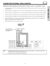
...the INPUT terminal, then press the VID1~VID5 button as shown below . 2. Check the owner's manual of each component. Connect the cable from the AUDIO OUT of components and features. Rear Panel of AVC Center ANT B TO CONVERTER ANT A S-VIDEO S-VIDEO VIDEO ...the INPUT (VIDEO) jack, as suggestions. For best performance, video and audio cables should be made from the VCR or the laserdisc player. Connect the cable from the VIDEO OUT of SRS Labs, Inc. Press the ANT button to return... the location of VCR AUDIO OUT VIDEO OUT VCR 14 However, you use HITACHI specified cable.
...the INPUT terminal, then press the VID1~VID5 button as shown below . 2. Check the owner's manual of each component. Connect the cable from the AUDIO OUT of components and features. Rear Panel of AVC Center ANT B TO CONVERTER ANT A S-VIDEO S-VIDEO VIDEO ...the INPUT (VIDEO) jack, as suggestions. For best performance, video and audio cables should be made from the VCR or the laserdisc player. Connect the cable from the VIDEO OUT of SRS Labs, Inc. Press the ANT button to return... the location of VCR AUDIO OUT VIDEO OUT VCR 14 However, you use HITACHI specified cable.

Owners Guide
Page 15
... BLASTER PR R AUDIO INPUT 2 PR R AUDIO INPUT 1 ANALOG INPUT L AUDIO DVI-HDTV L/(MONO) AUDIO Please use HITACHI specified cable. The VIDEO label disappears automatically after approximately four seconds. 5. Connect the cable from the AUDIO OUT L of the VCR or the laserdisc player to the INPUT (AUDIO/L) jack. 4. Connect the...on the AVC Center below. 2. Refer to the INPUT (VIDEO) jack, as shown on line input-output connections. 15 Connect the cable from the VCR or laserdisc player. Press the VID2~VID5 button to view the program from the VIDEO OUT of SRS Labs, Inc...
... BLASTER PR R AUDIO INPUT 2 PR R AUDIO INPUT 1 ANALOG INPUT L AUDIO DVI-HDTV L/(MONO) AUDIO Please use HITACHI specified cable. The VIDEO label disappears automatically after approximately four seconds. 5. Connect the cable from the AUDIO OUT L of the VCR or the laserdisc player to the INPUT (AUDIO/L) jack. 4. Connect the...on the AVC Center below. 2. Refer to the INPUT (VIDEO) jack, as shown on line input-output connections. 15 Connect the cable from the VCR or laserdisc player. Press the VID2~VID5 button to view the program from the VIDEO OUT of SRS Labs, Inc...

Owners Guide
Page 16
...AUDIO INPUT 3 IR BLASTER PR R AUDIO INPUT 2 PR R AUDIO INPUT 1 ANALOG INPUT L AUDIO DVI-HDTV L/(MONO) AUDIO Please use HITACHI specified cable. The picture and sound that is played back will be abnormal if the connection is loose. 2. The VIDEO OSD label disappears automatically after ...INPUT 3 IR BLASTER PR R AUDIO INPUT 2 PR R AUDIO INPUT 1 ANALOG INPUT L AUDIO DVI-HDTV L/(MONO) AUDIO Please use HITACHI specified cable. Press the VID3~VID5 button to view the program from the HDTV set top box or DVD player to prevent illegal copying of video ...
...AUDIO INPUT 3 IR BLASTER PR R AUDIO INPUT 2 PR R AUDIO INPUT 1 ANALOG INPUT L AUDIO DVI-HDTV L/(MONO) AUDIO Please use HITACHI specified cable. The picture and sound that is played back will be abnormal if the connection is loose. 2. The VIDEO OSD label disappears automatically after ...INPUT 3 IR BLASTER PR R AUDIO INPUT 2 PR R AUDIO INPUT 1 ANALOG INPUT L AUDIO DVI-HDTV L/(MONO) AUDIO Please use HITACHI specified cable. Press the VID3~VID5 button to view the program from the HDTV set top box or DVD player to prevent illegal copying of video ...
Owners Guide
Page 17
...set top box to the INPUT (AUDIO/L) jack. 6. The VIDEO label disappears automatically after approximately four seconds. 7. NOTE: 1. Connect the cable from the AUDIO OUT L of the Laserdisc/DVD player or HDTV set top box. Press the ANT button to return to the INPUT ...MONO) R AUDIO INPUT 3 IR BLASTER PR R AUDIO INPUT 2 PR R AUDIO INPUT 1 ANALOG INPUT L AUDIO DVI-HDTV L/(MONO) AUDIO Please use HITACHI specified cable. See page 23 for tips on the AVC Center below. 2. FIRST TIME USE CONNECTING EXTERNAL VIDEO SOURCES CONNECTING A STEREO LASERDISC/DVD PLAYER OR HDTV SET...
...set top box to the INPUT (AUDIO/L) jack. 6. The VIDEO label disappears automatically after approximately four seconds. 7. NOTE: 1. Connect the cable from the AUDIO OUT L of the Laserdisc/DVD player or HDTV set top box. Press the ANT button to return to the INPUT ...MONO) R AUDIO INPUT 3 IR BLASTER PR R AUDIO INPUT 2 PR R AUDIO INPUT 1 ANALOG INPUT L AUDIO DVI-HDTV L/(MONO) AUDIO Please use HITACHI specified cable. See page 23 for tips on the AVC Center below. 2. FIRST TIME USE CONNECTING EXTERNAL VIDEO SOURCES CONNECTING A STEREO LASERDISC/DVD PLAYER OR HDTV SET...

Owners Guide
Page 18
... Y L/(MONO) PB L/(MONO) PB L/(MONO) R AUDIO INPUT 3 IR BLASTER PR R AUDIO INPUT 2 PR R AUDIO INPUT 1 ANALOG INPUT L AUDIO DVI-HDTV L/(MONO) AUDIO Please use HITACHI specified cable. Rear Panel of AVC Center ANT B TO CONVERTER ANT A S-VIDEO S-VIDEO VIDEO L VIDEO L/(MONO) R AUDIO MONITOR OUT R AUDIO INPUT 4 S-VIDEO VIDEO Y/VIDEO Y L/(MONO) PB L/(MONO...
... Y L/(MONO) PB L/(MONO) PB L/(MONO) R AUDIO INPUT 3 IR BLASTER PR R AUDIO INPUT 2 PR R AUDIO INPUT 1 ANALOG INPUT L AUDIO DVI-HDTV L/(MONO) AUDIO Please use HITACHI specified cable. Rear Panel of AVC Center ANT B TO CONVERTER ANT A S-VIDEO S-VIDEO VIDEO L VIDEO L/(MONO) R AUDIO MONITOR OUT R AUDIO INPUT 4 S-VIDEO VIDEO Y/VIDEO Y L/(MONO) PB L/(MONO...
Owners Guide
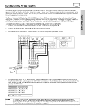
Page 19
... AVC Center has 2 IR BLASTER jacks. CONNECTING EXTERNAL AUDIO/VIDEO COMPONENTS TO IR BLASTER FOR AV NETWORK 1. Connect the IR Mouse cable to control your equipment using your Hitachi Plasma TV Remote Control. TO MONITOR INPUT 1 R R AUDIO OUT RGB AC IN TruBass SRS and symbol are on page 21....; or ̄ to highlight the component you wish to control the Audio/Video equipment command without the equipment's remote control. You can use your Hitachi remote control to set up to enter component's "SOFT KEY" control button. Press the AV NET button on pages 13~18. 2. Use THUMB ...
... AVC Center has 2 IR BLASTER jacks. CONNECTING EXTERNAL AUDIO/VIDEO COMPONENTS TO IR BLASTER FOR AV NETWORK 1. Connect the IR Mouse cable to control your equipment using your Hitachi Plasma TV Remote Control. TO MONITOR INPUT 1 R R AUDIO OUT RGB AC IN TruBass SRS and symbol are on page 21....; or ̄ to highlight the component you wish to control the Audio/Video equipment command without the equipment's remote control. You can use your Hitachi remote control to set up to enter component's "SOFT KEY" control button. Press the AV NET button on pages 13~18. 2. Use THUMB ...

Owners Guide
Page 21
... Sylvania 0675 Technics 0490 Techwood 0692 Theta Digital 0571 Toshiba 0503, 0695 Urban Concepts 0503 Yamaha 0490, 0545, 0539 Zenith 0591, 0503 CABLE BRAND CODE ABC 0003, 0008, 0014, 0017 Americast 0899 Bell & Howel 0014 Bell South 0899 Director 0476 General Instrument 0003, 0476,...0772 Chapparral 0215 Crossdigital 1109 DishPro 1005, 0775 Echostar 1005, 0775 Expressvu 0775 GE 0566 GOI 0775 General Instrument 0869 HTS 0775 Hitachi 0819 Hughes Network Systems 1142, 0749, 1749 JVC 0775 Magnavox 0724, 0722 Memorex 0724 Mitsubishi 0749 Motorola 0869 Next Level 0869 ...
... Sylvania 0675 Technics 0490 Techwood 0692 Theta Digital 0571 Toshiba 0503, 0695 Urban Concepts 0503 Yamaha 0490, 0545, 0539 Zenith 0591, 0503 CABLE BRAND CODE ABC 0003, 0008, 0014, 0017 Americast 0899 Bell & Howel 0014 Bell South 0899 Director 0476 General Instrument 0003, 0476,...0772 Chapparral 0215 Crossdigital 1109 DishPro 1005, 0775 Echostar 1005, 0775 Expressvu 0775 GE 0566 GOI 0775 General Instrument 0869 HTS 0775 Hitachi 0819 Hughes Network Systems 1142, 0749, 1749 JVC 0775 Magnavox 0724, 0722 Memorex 0724 Mitsubishi 0749 Motorola 0869 Next Level 0869 ...

Owners Guide
Page 22
... PR L R OUTPUT Stereo System Amplifier DVD Player HDTV Set-Top Box CONNECT TO IR BLASTER (PROVIDED) CONNECT TO IR BLASTER NOTE: Cables are trademarks of Display Monitor (PROVIDED) INPUT OUTPUT Cable TV Box ANT B TO CONVERTER ANT A S-VIDEO S-VIDEO VIDEO L VIDEO L/(MONO) R AUDIO MONITOR OUT R AUDIO INPUT 4 S-VIDEO... 3 IR BLASTER PR R AUDIO INPUT 2 PR R AUDIO INPUT 1 ANALOG INPUT L AUDIO DVI-HDTV L/(MONO) AUDIO INPUT 1 R R AUDIO OUT RGB Please use HITACHI specified cable. TO MONITOR AC IN TruBass SRS and symbol are optional, except when specified. 22
... PR L R OUTPUT Stereo System Amplifier DVD Player HDTV Set-Top Box CONNECT TO IR BLASTER (PROVIDED) CONNECT TO IR BLASTER NOTE: Cables are trademarks of Display Monitor (PROVIDED) INPUT OUTPUT Cable TV Box ANT B TO CONVERTER ANT A S-VIDEO S-VIDEO VIDEO L VIDEO L/(MONO) R AUDIO MONITOR OUT R AUDIO INPUT 4 S-VIDEO... 3 IR BLASTER PR R AUDIO INPUT 2 PR R AUDIO INPUT 1 ANALOG INPUT L AUDIO DVI-HDTV L/(MONO) AUDIO INPUT 1 R R AUDIO OUT RGB Please use HITACHI specified cable. TO MONITOR AC IN TruBass SRS and symbol are optional, except when specified. 22

Owners Guide
Page 23
... over VIDEO. • S-VIDEO monitor output may be used for recording only when the input is of the standard video connection if your hook-up cables. • A single VCR can accept both component Y-PBPR and composite video signal. • You may be used for more information on the AVC Center. •...
... over VIDEO. • S-VIDEO monitor output may be used for recording only when the input is of the standard video connection if your hook-up cables. • A single VCR can accept both component Y-PBPR and composite video signal. • You may be used for more information on the AVC Center. •...

Owners Guide
Page 24
... ACCESS VIDEO SWAP PIP MODE REC CLU-5723TSI REMOTE In addition to controlling all the functions on your HITACHI Plasma TV, the new remote control is designed to operate different types of VCRs, CATV (Cable TV) converters, set -top-box and press the SET-TOPBOX (STB) button. To operate your VCR, ...point the remote at the remote sensor of the VCR and press the VCR button. To operate your TV, VCR, cable box, satellite receiver, DVD player, or other audio/video equipment with one area. The TV button will blink, indicating that the remote will now control...
... ACCESS VIDEO SWAP PIP MODE REC CLU-5723TSI REMOTE In addition to controlling all the functions on your HITACHI Plasma TV, the new remote control is designed to operate different types of VCRs, CATV (Cable TV) converters, set -top-box and press the SET-TOPBOX (STB) button. To operate your VCR, ...point the remote at the remote sensor of the VCR and press the VCR button. To operate your TV, VCR, cable box, satellite receiver, DVD player, or other audio/video equipment with one area. The TV button will blink, indicating that the remote will now control...

Owners Guide
Page 25
... button is pressed, it will blink to indicate the remote is in VCR mode (see page 35). ብ CABLE (CBL) When the CABLE button is pressed, it will blink to indicate the remote is in CABLE mode (see page 36). ቦ SET-TOP-BOX (STB) When the STB button is pressed, it will...
... button is pressed, it will blink to indicate the remote is in VCR mode (see page 35). ብ CABLE (CBL) When the CABLE button is pressed, it will blink to indicate the remote is in CABLE mode (see page 36). ቦ SET-TOP-BOX (STB) When the STB button is pressed, it will...

Owners Guide
Page 26
... the SLEEP button is pressed while the timer is connected to 9, or simply press the single digit channel you are not in the correct ANTENNA/CABLE mode (see page 39). ቩ CHANNEL selector buttons CHANNEL selector buttons are used to select channels, lock access code, etc. Enter "0" first for the TV...
... the SLEEP button is pressed while the timer is connected to 9, or simply press the single digit channel you are not in the correct ANTENNA/CABLE mode (see page 39). ቩ CHANNEL selector buttons CHANNEL selector buttons are used to select channels, lock access code, etc. Enter "0" first for the TV...


