HP LaserJet MFP and Color MFP Products - Configuring Security for Multiple LaserJet MFP Products
Page 68
.... Firmware Firmware is upgraded with the latest firmware. New firmware is the power supply for it is a web page built into an MFP to the MFP network IP address. The formatter accommodates the MFP hard drive, the Compact Flash cards, the Jetdirect card, the CPU, ...lines using additional solutions on the front of an MFP. HP LaserJet and Color LaserJet MFP Security Checklist 68 EWS Embedded Web Server. Firmware can be locked using common tools), it . The ACL restricts network access to enhance MFP digital sending functionality and security. Since the formatter...
.... Firmware Firmware is upgraded with the latest firmware. New firmware is the power supply for it is a web page built into an MFP to the MFP network IP address. The formatter accommodates the MFP hard drive, the Compact Flash cards, the Jetdirect card, the CPU, ...lines using additional solutions on the front of an MFP. HP LaserJet and Color LaserJet MFP Security Checklist 68 EWS Embedded Web Server. Firmware can be locked using common tools), it . The ACL restricts network access to enhance MFP digital sending functionality and security. Since the formatter...

HP LaserJet MPF Products - Configuring Security for Multiple MFP Products
Page 85
... enhance MFP digital sending functionality and security. HP Jetdirect 635n Print Server The HP Jetdirect 635n Print Server is the power supply for network communications. It provides high-level security for the MFP. IPsec is not covered in it is the MFP capability of the MFPs include ... over network lines using common tools), it is an HP solution to LaserJet and Color LaserJet MFPs and printers. Edgeline MFPs This checklist abbreviates HP CM8050 Color MFP with Edgeline Technology and HP CM8060 Color MFP with Edgeline MFPs and it can be locked using hardware locks. PIN ...
... enhance MFP digital sending functionality and security. HP Jetdirect 635n Print Server The HP Jetdirect 635n Print Server is the power supply for network communications. It provides high-level security for the MFP. IPsec is not covered in it is the MFP capability of the MFPs include ... over network lines using common tools), it is an HP solution to LaserJet and Color LaserJet MFPs and printers. Edgeline MFPs This checklist abbreviates HP CM8050 Color MFP with Edgeline Technology and HP CM8060 Color MFP with Edgeline MFPs and it can be locked using hardware locks. PIN ...

HP LaserJet M3027/M3035 MFP - User Guide for Model Numbers CB414A/CB415A/CB416A/CB417A
Page 185
..., try the following actions: ● Check all covers and doors are printing small sizes (such as index cards), make sure that meets HP specifications. Staples can damage the device and can void warranty. ● Make sure that has had the staple removed. Do not print on... ● If you are printing from a different orientation. ● Check the media quality. Do not use media with staples or media that the power supplied to feed through the device from tray 1, try rotating the stack 180°. ● Try rotating media to the device is open during a print...
..., try the following actions: ● Check all covers and doors are printing small sizes (such as index cards), make sure that meets HP specifications. Staples can damage the device and can void warranty. ● Make sure that has had the staple removed. Do not print on... ● If you are printing from a different orientation. ● Check the media quality. Do not use media with staples or media that the power supplied to feed through the device from tray 1, try rotating the stack 180°. ● Try rotating media to the device is open during a print...

HP LaserJet M3027/M3035 MFP - User Guide for Model Numbers CC476A/CC477A/CC478A/CC479A
Page 185
...● Use only media that has had the staple removed. Staples can damage the device and can void warranty. ● Make sure that the power supplied to separate each sheet. Solve repeated jams If jams occur frequently, try the following actions: ● Check all covers and doors are closed. (... together. 5. See Media considerations on page 219. See Specifications on page 58. ● Do not use media with staples or media that meets HP specifications. A piece of envelopes, transparencies, vellum, or labels. ● Do not use media that has already been used in the trays, that...
...● Use only media that has had the staple removed. Staples can damage the device and can void warranty. ● Make sure that the power supplied to separate each sheet. Solve repeated jams If jams occur frequently, try the following actions: ● Check all covers and doors are closed. (... together. 5. See Media considerations on page 219. See Specifications on page 58. ● Do not use media with staples or media that meets HP specifications. A piece of envelopes, transparencies, vellum, or labels. ● Do not use media that has already been used in the trays, that...

Service Manual
Page 8
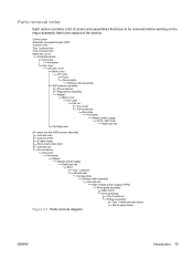
...flowchart 193 1. Fax accessory ...111 Disk drive ...113 Formatter ...116 Stapler ...117 Stapler power-supply ...123 Right-side fan ...128 Engine control unit (ECU) ...131 Left-side riser ...138 Fuser ...139 Laser/scanner ...142 Access plate ...144 Oblique-roller assembly ...146 Left-side fan ...148 High...-voltage power supply (HVPS 149 Feed-guide assembly ...156 Main motor ...159 Gear assembly ...162 Reinstallation ...
...flowchart 193 1. Fax accessory ...111 Disk drive ...113 Formatter ...116 Stapler ...117 Stapler power-supply ...123 Right-side fan ...128 Engine control unit (ECU) ...131 Left-side riser ...138 Fuser ...139 Laser/scanner ...142 Access plate ...144 Oblique-roller assembly ...146 Left-side fan ...148 High...-voltage power supply (HVPS 149 Feed-guide assembly ...156 Main motor ...159 Gear assembly ...162 Reinstallation ...
Service Manual
Page 72
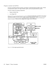
... general structure 60 Chapter 4 Theory of the ECU to commands that the formatter sends. Figure 4-7 LVPS circuit diagram on page 61 shows the low-voltage power supply circuit on the ECU. It drives the laser/scanner system, the image formation system, and the pickup/feed/delivery system.
... general structure 60 Chapter 4 Theory of the ECU to commands that the formatter sends. Figure 4-7 LVPS circuit diagram on page 61 shows the low-voltage power supply circuit on the ECU. It drives the laser/scanner system, the image formation system, and the pickup/feed/delivery system.

Service Manual
Page 73
... circuit diagram ENWW Basic operation 61 Sensors High-voltage power supply circuit Sensor Fuser unit Cartridge Fans Formatter Low-voltage power supply circuit Fuser control circuit Memory tag control circuit Fan motor drive control circuit ECU CPU IC401 Video IF control circuit High-voltage control circuit Laser control circuit Scanner motor control circuit Sequence control...
... circuit diagram ENWW Basic operation 61 Sensors High-voltage power supply circuit Sensor Fuser unit Cartridge Fans Formatter Low-voltage power supply circuit Fuser control circuit Memory tag control circuit Fan motor drive control circuit ECU CPU IC401 Video IF control circuit High-voltage control circuit Laser control circuit Scanner motor control circuit Sequence control...

Service Manual
Page 87
...● Fax accessory ● Disk drive ● Formatter ● Stapler ● Stapler power-supply ● Right-side fan ● Engine control unit (ECU) ● Left-side riser ● Fuser ● Laser/scanner ● Access plate ● Oblique-roller assembly ● Left-side fan ●... High-voltage power supply (HVPS) ● Feed-guide assembly ● Main motor ● Gear assembly ● ...
...● Fax accessory ● Disk drive ● Formatter ● Stapler ● Stapler power-supply ● Right-side fan ● Engine control unit (ECU) ● Left-side riser ● Fuser ● Laser/scanner ● Access plate ● Oblique-roller assembly ● Left-side fan ●... High-voltage power supply (HVPS) ● Feed-guide assembly ● Main motor ● Gear assembly ● ...
Service Manual
Page 91
... Back cover I/O cover Fax rail Top cover Fax accessory Disk drive Formatter Stapler power-supply Front, right cover Right-side fan Cartridge door All covers and the ADF/scanner assembly Left-side riser Laser/scanner E-label reader Face-down-roller shaft Left-side fan Fax accessory Disk drive... Formatter Stapler Stapler power-supply Right-side fan ECU Tray 1 solenoid Left-side riser Access plate Oblique-roller assembly...
... Back cover I/O cover Fax rail Top cover Fax accessory Disk drive Formatter Stapler power-supply Front, right cover Right-side fan Cartridge door All covers and the ADF/scanner assembly Left-side riser Laser/scanner E-label reader Face-down-roller shaft Left-side fan Fax accessory Disk drive... Formatter Stapler Stapler power-supply Right-side fan ECU Tray 1 solenoid Left-side riser Access plate Oblique-roller assembly...

Service Manual
Page 134
...both tests, replace the stapler and the stapler power supply. If the stapler fails either test, remove the stapler and then reinstall it by carefully following the installation steps shown in this manual. WARNING! When the stapler power supply is open, and the stapler cannot be repaired... without ordering parts, disconnect the stapler power supply before reassembling the device and before you leave the customer site. If the staple activates...
...both tests, replace the stapler and the stapler power supply. If the stapler fails either test, remove the stapler and then reinstall it by carefully following the installation steps shown in this manual. WARNING! When the stapler power supply is open, and the stapler cannot be repaired... without ordering parts, disconnect the stapler power supply before reassembling the device and before you leave the customer site. If the staple activates...

Service Manual
Page 135
Stapler power-supply 1. Remove two screws (callout 1) from the side of the I/O plate and one screw (callout 2) from the back of the plate. 2 1 Figure 5-44 Removing the stapler power supply (1 of 5) ENWW Stapler power-supply 123 Remove the following components: ● All covers except for the top cover and the right, front cover (see Covers on page 94) ● ADF/scanner assembly (see Scanner assembly on page 90) ● Fax accessory (see Fax accessory on page 111) ● Formatter (see Formatter on page 116) ● Stapler (see Stapler on page 117) 2.
Stapler power-supply 1. Remove two screws (callout 1) from the side of the I/O plate and one screw (callout 2) from the back of the plate. 2 1 Figure 5-44 Removing the stapler power supply (1 of 5) ENWW Stapler power-supply 123 Remove the following components: ● All covers except for the top cover and the right, front cover (see Covers on page 94) ● ADF/scanner assembly (see Scanner assembly on page 90) ● Fax accessory (see Fax accessory on page 111) ● Formatter (see Formatter on page 116) ● Stapler (see Stapler on page 117) 2.

Service Manual
Page 136
3. Lift the I/O plate up slightly to dislodge it from the tabs (callout 3) on the ECU plate, and then slide it toward the back and off of the device. 3 Figure 5-45 Removing the stapler power supply (2 of 5) 124 Chapter 5 Removal and replacement ENWW
3. Lift the I/O plate up slightly to dislodge it from the tabs (callout 3) on the ECU plate, and then slide it toward the back and off of the device. 3 Figure 5-45 Removing the stapler power supply (2 of 5) 124 Chapter 5 Removal and replacement ENWW

Service Manual
Page 137
Remove three screws (callout 4) from the stapler-power-supply plate. 4 Figure 5-46 Removing the stapler power supply (3 of 5) ENWW Stapler power-supply 125 4.
Remove three screws (callout 4) from the stapler-power-supply plate. 4 Figure 5-46 Removing the stapler power supply (3 of 5) ENWW Stapler power-supply 125 4.

Service Manual
Page 138
Slide the stapler-power-supply plate toward the back of 5) Reinstallation tip Guide the cables through a hole in the stapler-power-supply plate before attaching the plate. 126 Chapter 5 Removal and replacement ENWW 5. Figure 5-47 Removing the stapler power supply (4 of the device until it stops, and then guide cables through the hole in the stapler-power-supply plate while lifting the plate straight away from the device.
Slide the stapler-power-supply plate toward the back of 5) Reinstallation tip Guide the cables through a hole in the stapler-power-supply plate before attaching the plate. 126 Chapter 5 Removal and replacement ENWW 5. Figure 5-47 Removing the stapler power supply (4 of the device until it stops, and then guide cables through the hole in the stapler-power-supply plate while lifting the plate straight away from the device.

Service Manual
Page 139
6. Unplug the power-supply cable (callout 5) and then remove one screw (callout 6) to release the power-supply cover. 5 6 Figure 5-48 Removing the stapler power supply (5 of the plate. ENWW Stapler power-supply 127 Lift the cover off of the power supply and then lift the power supply off of 5) 7.
6. Unplug the power-supply cable (callout 5) and then remove one screw (callout 6) to release the power-supply cover. 5 6 Figure 5-48 Removing the stapler power supply (5 of the plate. ENWW Stapler power-supply 127 Lift the cover off of the power supply and then lift the power supply off of 5) 7.

Service Manual
Page 140
Remove the following components: ● All covers except for the top cover (see Covers on page 94) ● ADF/scanner assembly (see Scanner assembly on page 90) ● Fax accessory (see Fax accessory on page 111) ● Disk drive (see Disk drive on page 113) ● Formatter (see Formatter on page 116) ● Stapler (see Stapler on page 117) and stapler power-supply (see Stapler power-supply on page 123) 2. Remove the grounding wire (callout 1) from the fan housing. 1 Figure 5-49 Removing the right-side fan (1 of 3) 128 Chapter 5 Removal and replacement ENWW Right-side fan 1.
Remove the following components: ● All covers except for the top cover (see Covers on page 94) ● ADF/scanner assembly (see Scanner assembly on page 90) ● Fax accessory (see Fax accessory on page 111) ● Disk drive (see Disk drive on page 113) ● Formatter (see Formatter on page 116) ● Stapler (see Stapler on page 117) and stapler power-supply (see Stapler power-supply on page 123) 2. Remove the grounding wire (callout 1) from the fan housing. 1 Figure 5-49 Removing the right-side fan (1 of 3) 128 Chapter 5 Removal and replacement ENWW Right-side fan 1.

Service Manual
Page 143
...) ● Disk drive (see Disk drive on page 113) ● Formatter (see Formatter on page 116) ● Stapler (see Stapler on page 117) and stapler power-supply (see Stapler power-supply on page 123) ● Right-side fan (see Right-side fan on page 128) 2.
...) ● Disk drive (see Disk drive on page 113) ● Formatter (see Formatter on page 116) ● Stapler (see Stapler on page 117) and stapler power-supply (see Stapler power-supply on page 123) ● Right-side fan (see Right-side fan on page 128) 2.

Service Manual
Page 161
...) 1. Tip the device so that it rests on the workspace. 2. ENWW High-voltage power supply (HVPS) 149 After removing the fan from its top. Remove the following components: ● All covers (see Covers on page 94) and the ADF/scanner ...; Disk drive (see Disk drive on page 113) ● Formatter (see Formatter on page 116) ● Stapler (see Stapler on page 117) and stapler power-supply (see Stapler power-supply on page 123) ● ECU (see Engine control unit (ECU) on page 131) ● Left-side riser (see Left-side riser on page 138...
...) 1. Tip the device so that it rests on the workspace. 2. ENWW High-voltage power supply (HVPS) 149 After removing the fan from its top. Remove the following components: ● All covers (see Covers on page 94) and the ADF/scanner ...; Disk drive (see Disk drive on page 113) ● Formatter (see Formatter on page 116) ● Stapler (see Stapler on page 117) and stapler power-supply (see Stapler power-supply on page 123) ● ECU (see Engine control unit (ECU) on page 131) ● Left-side riser (see Left-side riser on page 138...

Service Manual
Page 163
At the left side of the device, disconnect one cable (callout 2) and then remove two screws (callout 3). 3 2 Figure 5-72 Removing the HVPS (2 of 5) Reinstallation tip Remember how the cable is threaded and connected to the device. ENWW High-voltage power supply (HVPS) 151 4.
At the left side of the device, disconnect one cable (callout 2) and then remove two screws (callout 3). 3 2 Figure 5-72 Removing the HVPS (2 of 5) Reinstallation tip Remember how the cable is threaded and connected to the device. ENWW High-voltage power supply (HVPS) 151 4.

Service Manual
Page 165
6. Guide the ribbon cable (callout 6) through the hole in the chassis and then remove the remaining three screws (callout 7) from the HVPS pan. 6 7 Figure 5-74 Removing the HVPS (4 of 5) ENWW High-voltage power supply (HVPS) 153
6. Guide the ribbon cable (callout 6) through the hole in the chassis and then remove the remaining three screws (callout 7) from the HVPS pan. 6 7 Figure 5-74 Removing the HVPS (4 of 5) ENWW High-voltage power supply (HVPS) 153


