Service Manual
Page 11
...After completing service 222 Screws that are used in the MFP 222 User-replaceable parts ...224 Print cartridge ...224 Control-panel overlays ...224 Control panel ...225 Transfer roller ...226 ADF input tray ...227 ADF pickup and feed rollers 228 ADF separation pad ...229 ADF delivery guide (clear...-bin assembly ...233 Duplex-printing unit ...234 Fuser-entrance guide ...235 Fuser ...235 Tray 2, 3, 4, or 5 pickup and feed rollers 236 Tray 1 pickup roller ...237 Scanner filter cover and scanner filter 238 ADF-hinge flap ...239 Formatter cover and formatter 240 Hard drive ...242 DIMM ...243 ...
...After completing service 222 Screws that are used in the MFP 222 User-replaceable parts ...224 Print cartridge ...224 Control-panel overlays ...224 Control panel ...225 Transfer roller ...226 ADF input tray ...227 ADF pickup and feed rollers 228 ADF separation pad ...229 ADF delivery guide (clear...-bin assembly ...233 Duplex-printing unit ...234 Fuser-entrance guide ...235 Fuser ...235 Tray 2, 3, 4, or 5 pickup and feed rollers 236 Tray 1 pickup roller ...237 Scanner filter cover and scanner filter 238 ADF-hinge flap ...239 Formatter cover and formatter 240 Hard drive ...242 DIMM ...243 ...
Service Manual
Page 15
... the Service ID 462 Converting the service ID to an actual date 462 Troubleshooting the embedded HP Jetdirect print server 463 Firmware-stack trace ...464 Solve common Windows problems 465 Solve common Macintosh... 472 How to use the parts lists and diagrams 472 Screws that are used in the MFP ...473 Customer-replaceable parts and accessories 474 Accessories ...474 Customer-replaceable components (print engine 476...Lifter-drive assembly ...516 Cassette ...518 Paper-feed roller assembly 520 Registration assembly ...522 Multipurpose assembly ...524 Reverse assembly ...526 ENWW xiii
... the Service ID 462 Converting the service ID to an actual date 462 Troubleshooting the embedded HP Jetdirect print server 463 Firmware-stack trace ...464 Solve common Windows problems 465 Solve common Macintosh... 472 How to use the parts lists and diagrams 472 Screws that are used in the MFP ...473 Customer-replaceable parts and accessories 474 Accessories ...474 Customer-replaceable components (print engine 476...Lifter-drive assembly ...516 Cassette ...518 Paper-feed roller assembly 520 Registration assembly ...522 Multipurpose assembly ...524 Reverse assembly ...526 ENWW xiii
Service Manual
Page 130
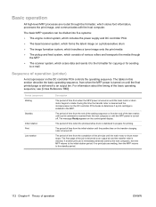
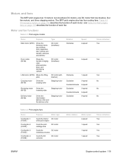
...is immediately detected (sent by the host computer), then the MFP returns to the initial rotation period. If another print job is stabilized to prepare for sending to e-mail Sequence of operation (printer) A microprocessor on the transfer-charging roller is received from the end of the last rotation until ... information, processes the print image, and communicates with the host computer. The tables in the MFP. The final page of the job is delivered to an output bin and the transfer roller is delivered to an output bin. The message Ready appears on a photosensitive drum ● The...
...is immediately detected (sent by the host computer), then the MFP returns to the initial rotation period. If another print job is stabilized to prepare for sending to e-mail Sequence of operation (printer) A microprocessor on the transfer-charging roller is received from the end of the last rotation until ... information, processes the print image, and communicates with the host computer. The tables in the MFP. The final page of the job is delivered to an output bin and the transfer roller is delivered to an output bin. The message Ready appears on a photosensitive drum ● The...
Service Manual
Page 137
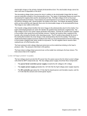
...Motor rotation Motor speed 2-speed 1-speed 1-speed 1-speed Failure detection Yes Yes Yes Yes ENWW Engine-control system 119 Motors and fans The MFP print engine has 10 motors: two brushless DC motors, one DC motor that has brushes, four fan motors, and three stepping motors. Motor... and fan functions Table 4-1 Print-engine motors Name Purpose Type Main motor (M101) Drives the following rollers: tray 2 pickup, feed, separation, tray 1 pickup, pretransfer, pressure, and delivery DC motor (brushless) Drum motor (M102) Drives the transfer-charging...
...Motor rotation Motor speed 2-speed 1-speed 1-speed 1-speed Failure detection Yes Yes Yes Yes ENWW Engine-control system 119 Motors and fans The MFP print engine has 10 motors: two brushless DC motors, one DC motor that has brushes, four fan motors, and three stepping motors. Motor... and fan functions Table 4-1 Print-engine motors Name Purpose Type Main motor (M101) Drives the following rollers: tray 2 pickup, feed, separation, tray 1 pickup, pretransfer, pressure, and delivery DC motor (brushless) Drum motor (M102) Drives the transfer-charging...
Service Manual
Page 143
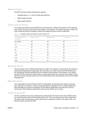
...image on the photosensitive drum. The transfer voltage (bias) transfers the toner image on one another and then applied to the primary charging roller, which transfers the biases to the media. Transfer DC positive bias is not present. Two types of developing biases are used: the ...9679; The DC controller generates the +5 Vdc that the laser/scanner and formatter require, and the +3.3 Vdc that the MFP components use. Two types of the transfer roller. The fuser-sleeve bias is DC-positive. ENWW Engine-control system 125 The high-voltage circuit on the primary charged ...
...image on the photosensitive drum. The transfer voltage (bias) transfers the toner image on one another and then applied to the primary charging roller, which transfers the biases to the media. Transfer DC positive bias is not present. Two types of developing biases are used: the ...9679; The DC controller generates the +5 Vdc that the laser/scanner and formatter require, and the +3.3 Vdc that the MFP components use. Two types of the transfer roller. The fuser-sleeve bias is DC-positive. ENWW Engine-control system 125 The high-voltage circuit on the primary charged ...

Service Manual
Page 150
... ● When the DC controller PCA receives a command from the formatter Writing timing ● When printing is EEPROM built into the cartridge, so that the MFP can detect the cartridge conditions. Cartridge memory The cartridge memory is completed ● When the DC controller PCA receives a command from the DC controller PCA... rotations and the toner level. The cartridge memory read /write process is passed to the memory. Print cartridge The print cartridge contains the primary-charging roller, photosensitive drum, and developing cylinder.
... ● When the DC controller PCA receives a command from the formatter Writing timing ● When printing is EEPROM built into the cartridge, so that the MFP can detect the cartridge conditions. Cartridge memory The cartridge memory is completed ● When the DC controller PCA receives a command from the DC controller PCA... rotations and the toner level. The cartridge memory read /write process is passed to the memory. Print cartridge The print cartridge contains the primary-charging roller, photosensitive drum, and developing cylinder.

Service Manual
Page 153
... The pickup-and-feed system consists of these sensors, see Figure 4-13 Motor, clutch, and solenoid locations on the tray 1 pickup assembly; The MFP uses tray 1 (the manual feeding tray) and a cassette in tray 1. The delivery operation uses five motors (M101, M102, M104, M105, ...paper path, but pages are discussed later in reversing unit that the printer motors drive. The MFP has a built-in this chapter. These input and output accessories are stacked in tray 2. For the locations of various rollers that can be installed. The tray 1 paper sensor (on page 136...
... The pickup-and-feed system consists of these sensors, see Figure 4-13 Motor, clutch, and solenoid locations on the tray 1 pickup assembly; The MFP uses tray 1 (the manual feeding tray) and a cassette in tray 1. The delivery operation uses five motors (M101, M102, M104, M105, ...paper path, but pages are discussed later in reversing unit that the printer motors drive. The MFP has a built-in this chapter. These input and output accessories are stacked in tray 2. For the locations of various rollers that can be installed. The tray 1 paper sensor (on page 136...
Service Manual
Page 159
... the presence of the cassette, and it detects the size of media is fed into the MFP. PS112 detects media that the formatter specifies, the DC controller sends a signal to swing down, and the pickup roller contacts the surface of the media by measuring the time between detecting the leading and trailing... edges. One sheet of the media that is attached to the pickup roller to the formatter. If the media size that PS103 measures is shorter than the media size that is loaded in the cassette. If either of...
... the presence of the cassette, and it detects the size of media is fed into the MFP. PS112 detects media that the formatter specifies, the DC controller sends a signal to swing down, and the pickup roller contacts the surface of the media by measuring the time between detecting the leading and trailing... edges. One sheet of the media that is attached to the pickup roller to the formatter. If the media size that PS103 measures is shorter than the media size that is loaded in the cassette. If either of...

Service Manual
Page 161
... are picked up, however, the low friction force between the sheets weakens the rotational force from the feed roller to the separation roller. Multifeed prevention The MFP uses the separation roller in tray 2 to have a stabilized pickup operation regardless of the size of the separation... roller and rotates it in the same direction as the feed roller. Consequently, the torque limiter takes control of the media in the tray 2...
... are picked up, however, the low friction force between the sheets weakens the rotational force from the feed roller to the separation roller. Multifeed prevention The MFP uses the separation roller in tray 2 to have a stabilized pickup operation regardless of the size of the separation... roller and rotates it in the same direction as the feed roller. Consequently, the torque limiter takes control of the media in the tray 2...

Service Manual
Page 163
...overall print speed is corrected and the registration shutter opens. Media-skew prevention The MFP uses a registration shutter on the registration assembly to sag. When the shutter opens, the media can continue into the printer paper path. When the entire leading edge comes in full contact with the ...shutter, the media skew is not affected. When the leading edge of the media contacts the shutter ENWW Pickup, feed, and delivery system 145 The feed roller continues to rotate...
...overall print speed is corrected and the registration shutter opens. Media-skew prevention The MFP uses a registration shutter on the registration assembly to sag. When the shutter opens, the media can continue into the printer paper path. When the entire leading edge comes in full contact with the ...shutter, the media skew is not affected. When the leading edge of the media contacts the shutter ENWW Pickup, feed, and delivery system 145 The feed roller continues to rotate...
Service Manual
Page 169
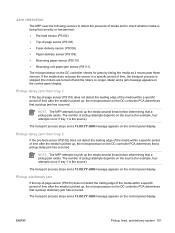
...paper-jam sensor (PS111) The microprocessor on the DC controller checks for jams by timing the media as it moves past these sensors. NOTE The MFP attempts to pick up , the microprocessor on the DC controller PCA determines that a pickup stationary jam has occurred. Pickup delay jam from tray ...the presence of media and to check whether media is stopped (the motors are turned off and the rollers no longer rotate) and a jam message appears on the control-panel display. NOTE The MFP attempts to pick up , the microprocessor on the control-panel display. The transport process stops and ...
...paper-jam sensor (PS111) The microprocessor on the DC controller checks for jams by timing the media as it moves past these sensors. NOTE The MFP attempts to pick up , the microprocessor on the DC controller PCA determines that a pickup stationary jam has occurred. Pickup delay jam from tray ...the presence of media and to check whether media is stopped (the motors are turned off and the rollers no longer rotate) and a jam message appears on the control-panel display. NOTE The MFP attempts to pick up , the microprocessor on the control-panel display. The transport process stops and ...
Service Manual
Page 178
... media and the stack height in the 3-bin mailbox. The 3-bin mailbox has the following components: ● One feed motor that drives the rollers ● Two solenoids that operate the inlet deflector and the bin deflector ● Six sensors that detect the presence of operation ENWW 3-bin mailbox...● One switch that determines whether the 3-bin mailbox is installed, it receives print media from the print engine and delivers it to the MFP correctly ● One fan that cools components inside the 3-bin mailbox The 3-bin mailbox has three operating modes: stacker mode, mailbox mode, and...
... media and the stack height in the 3-bin mailbox. The 3-bin mailbox has the following components: ● One feed motor that drives the rollers ● Two solenoids that operate the inlet deflector and the bin deflector ● Six sensors that detect the presence of operation ENWW 3-bin mailbox...● One switch that determines whether the 3-bin mailbox is installed, it receives print media from the print engine and delivers it to the MFP correctly ● One fan that cools components inside the 3-bin mailbox The 3-bin mailbox has three operating modes: stacker mode, mailbox mode, and...
Service Manual
Page 242
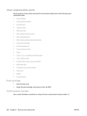
...two control-panel overlays (callout 1). 224 Chapter 5 Removal and replacement ENWW Grasp the print cartridge, and remove it from the MFP. User-replaceable parts The procedures in this section describe the removal and replacement of the following userreplaceable parts: ● Print ...-bin assembly ● Duplex-printing unit ● Fuser-entrance guide ● Fuser ● Tray 2, 3, 4, or 5 pickup and feed rollers ● Tray 1 pickup roller ● Scanner filter cover and scanner filter ● ADF-hinge flap ● Formatter cover and formatter ● Hard drive ● DIMM ...
...two control-panel overlays (callout 1). 224 Chapter 5 Removal and replacement ENWW Grasp the print cartridge, and remove it from the MFP. User-replaceable parts The procedures in this section describe the removal and replacement of the following userreplaceable parts: ● Print ...-bin assembly ● Duplex-printing unit ● Fuser-entrance guide ● Fuser ● Tray 2, 3, 4, or 5 pickup and feed rollers ● Tray 1 pickup roller ● Scanner filter cover and scanner filter ● ADF-hinge flap ● Formatter cover and formatter ● Hard drive ● DIMM ...
Service Manual
Page 247
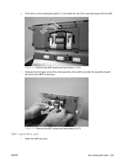
Release the front (gear end) of the roller-assembly drive-shaft, and slide the assembly toward the front of 2) ADF separation pad 1. 2. Figure 5-9 Remove the ADF pickup and feed rollers (2 of the MFP to remove it. Figure 5-8 Remove the ADF pickup and feed rollers (1 of the assembly away from the ADF. Push down on the locking tab (callout 1), and rotate the top of 2) 3. Open the ADF top cover ENWW User-replaceable parts 229
Release the front (gear end) of the roller-assembly drive-shaft, and slide the assembly toward the front of 2) ADF separation pad 1. 2. Figure 5-9 Remove the ADF pickup and feed rollers (2 of the MFP to remove it. Figure 5-8 Remove the ADF pickup and feed rollers (1 of the assembly away from the ADF. Push down on the locking tab (callout 1), and rotate the top of 2) 3. Open the ADF top cover ENWW User-replaceable parts 229
Service Manual
Page 254
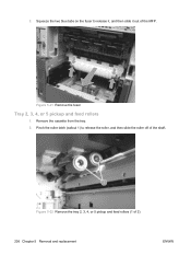
2. Pinch the roller latch (callout 1) to release it, and then slide it out of the shaft. Squeeze the two blue tabs on the fuser to release the roller, and then slide the roller off of the MFP. Figure 5-22 Remove the tray 2, 3, 4, or 5 pickup and feed rollers (1 of 2) 236 Chapter 5 Removal and replacement ENWW Figure 5-21 Remove the fuser Tray 2, 3, 4, or 5 pickup and feed rollers 1. Remove the cassette from the tray. 2.
2. Pinch the roller latch (callout 1) to release it, and then slide it out of the shaft. Squeeze the two blue tabs on the fuser to release the roller, and then slide the roller off of the MFP. Figure 5-22 Remove the tray 2, 3, 4, or 5 pickup and feed rollers (1 of 2) 236 Chapter 5 Removal and replacement ENWW Figure 5-21 Remove the fuser Tray 2, 3, 4, or 5 pickup and feed rollers 1. Remove the cassette from the tray. 2.
Service Manual
Page 296
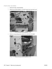
Remove two screws (callout 1), and then remove the inner front cover. Figure 5-97 Remove the feed-roller assembly (2 of the MFP. Remove one grounding screw (callout 2) on the front of 4) 278 Chapter 5 Removal and replacement ENWW Figure 5-96 Remove the feed-roller assembly (1 of 4) 3. Feed-roller assembly 1. Remove the tray 1 feed-assembly. 2.
Remove two screws (callout 1), and then remove the inner front cover. Figure 5-97 Remove the feed-roller assembly (2 of the MFP. Remove one grounding screw (callout 2) on the front of 4) 278 Chapter 5 Removal and replacement ENWW Figure 5-96 Remove the feed-roller assembly (1 of 4) 3. Feed-roller assembly 1. Remove the tray 1 feed-assembly. 2.
Service Manual
Page 297
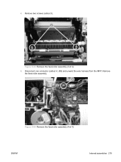
J89) and unwind the wire harness from the MFP. Figure 5-99 Remove the feed-roller assembly (4 of 4) 5. Remove the feed-roller assembly. 4. Remove two screws (callout 3). Disconnect one connector (callout 4; Figure 5-98 Remove the feed-roller assembly (3 of 4) ENWW Internal assemblies 279
J89) and unwind the wire harness from the MFP. Figure 5-99 Remove the feed-roller assembly (4 of 4) 5. Remove the feed-roller assembly. 4. Remove two screws (callout 3). Disconnect one connector (callout 4; Figure 5-98 Remove the feed-roller assembly (3 of 4) ENWW Internal assemblies 279
Service Manual
Page 298
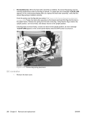
... error message 13.20.00 JAM appears on the control-panel display when the MFP power is installed correctly. Verify that this sensor-flag spring is turned on the flag. Reinstallation tip: When the feed-roller assembly is installed, the sensor-flag spring must be correctly positioned in Figure 5-100... Sensor-flag spring placement on the control-panel display after you replace the feed-roller assembly, verify that the flag is held in the plastic frame. If the flag does not move freely, and always returns to the ...
... error message 13.20.00 JAM appears on the control-panel display when the MFP power is installed correctly. Verify that this sensor-flag spring is turned on the flag. Reinstallation tip: When the feed-roller assembly is installed, the sensor-flag spring must be correctly positioned in Figure 5-100... Sensor-flag spring placement on the control-panel display after you replace the feed-roller assembly, verify that the flag is held in the plastic frame. If the flag does not move freely, and always returns to the ...
Service Manual
Page 316
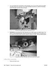
... small, flat-blade screwdriver to unlatch the retaining hook on the cassette feed-roller shaft to keep the shaft from slipping into MFP. Put pressure on the gear, and then remove the gear. Figure 5-134 Cassette feed-roller shaft (push here while replacing the gear) Lifter-drive assembly 1. CAUTION:... Do not let the pickup roller shaft slide into can get stuck on this ...
... small, flat-blade screwdriver to unlatch the retaining hook on the cassette feed-roller shaft to keep the shaft from slipping into MFP. Put pressure on the gear, and then remove the gear. Figure 5-134 Cassette feed-roller shaft (push here while replacing the gear) Lifter-drive assembly 1. CAUTION:... Do not let the pickup roller shaft slide into can get stuck on this ...
Service Manual
Page 386
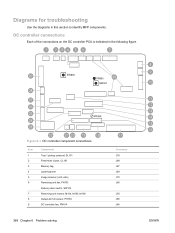
Figure 6-1 DC controller component connections Item 1 2 3 4 5 6 7 8 9 Component Tray 1 pickup solenoid, SL101 Feed-roller clutch, CL101 Memory tag Laser/scanner Image scanner (+24 volts) Reversing-unit fan, FN103 Delivery-door switch, SW103 Reversing-unit motors: M104, M105, M106 Output-... J70 J65 J50 J85 J66 ENWW DC controller connections Each of the connections on the DC controller PCA is indicated in this section to identify MFP components. Diagrams for troubleshooting Use the diagrams in the following figure.
Figure 6-1 DC controller component connections Item 1 2 3 4 5 6 7 8 9 Component Tray 1 pickup solenoid, SL101 Feed-roller clutch, CL101 Memory tag Laser/scanner Image scanner (+24 volts) Reversing-unit fan, FN103 Delivery-door switch, SW103 Reversing-unit motors: M104, M105, M106 Output-... J70 J65 J50 J85 J66 ENWW DC controller connections Each of the connections on the DC controller PCA is indicated in this section to identify MFP components. Diagrams for troubleshooting Use the diagrams in the following figure.


