Manual
Page 3
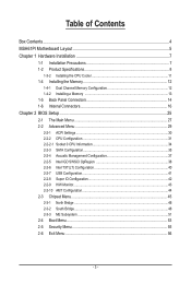
... 8 1-3-2 Installing the CPU Cooler 11 1-4 Installing the Memory 12 1-4-1 Dual Channel Memory Configuration 12 1-4-2 Installing a Memory 13 1-5 Back Panel Connectors 14 1-6 Internal Connectors 16 Chapter 2 BIOS Setup 25 2-1 The Main Menu 27 2-2 Advanced Menu 29 2-2-1 ACPI Settings...30 2-2-2 CPU Configuration 31 2-2-2-1 Socket 0 CPU Information 34 2-2-3 SATA Configuration 35 2-2-4 Acoustic Management Configuration...
... 8 1-3-2 Installing the CPU Cooler 11 1-4 Installing the Memory 12 1-4-1 Dual Channel Memory Configuration 12 1-4-2 Installing a Memory 13 1-5 Back Panel Connectors 14 1-6 Internal Connectors 16 Chapter 2 BIOS Setup 25 2-1 The Main Menu 27 2-2 Advanced Menu 29 2-2-1 ACPI Settings...30 2-2-2 CPU Configuration 31 2-2-2-1 Socket 0 CPU Information 34 2-2-3 SATA Configuration 35 2-2-4 Acoustic Management Configuration...

Manual
Page 15
Hardware Monitor BIOS ŠŠ CPU/System temperature detection ŠŠ CPU fan speed detection ŠŠ 1 x 64 Mbit flash ŠŠ AMI BIOS Form Factor ŠŠ Mini ITX Form Factor; 170cm x 170cm * GIGABYTE reserves the right to make any changes to the product specifications and product-related information without prior notice. - 9 - Hardware Installation
Hardware Monitor BIOS ŠŠ CPU/System temperature detection ŠŠ CPU fan speed detection ŠŠ 1 x 64 Mbit flash ŠŠ AMI BIOS Form Factor ŠŠ Mini ITX Form Factor; 170cm x 170cm * GIGABYTE reserves the right to make any changes to the product specifications and product-related information without prior notice. - 9 - Hardware Installation
Manual
Page 18
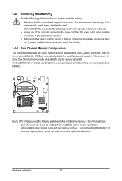
.... Enabling Dual Channel memory mode will automatically detect the specifications and capacity of the memory. Hardware Installation - 12 - A memory module can be used . (Go to GIGABYTE's website for optimum performance. When enabling Dual Channel mode with two memory modules, it is recommended that memory of the same capacity, brand, speed, and... as following: SODIMMB1 SODIMMA1 Due to CPU limitations, read the following guidelines before installing the memory in only one DDR3 memory module is installed, the BIOS will double the original memory bandwidth.
.... Enabling Dual Channel memory mode will automatically detect the specifications and capacity of the memory. Hardware Installation - 12 - A memory module can be used . (Go to GIGABYTE's website for optimum performance. When enabling Dual Channel mode with two memory modules, it is recommended that memory of the same capacity, brand, speed, and... as following: SODIMMB1 SODIMMA1 Due to CPU limitations, read the following guidelines before installing the memory in only one DDR3 memory module is installed, the BIOS will double the original memory bandwidth.
Manual
Page 20
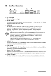
...supported depend on the monitor being used. • When After installing the HDMI device, make sure the default device for details.), and enter BIOS Setup, then set Onboard VGA output connect to an external audio system that your audio system provides an optical digital audio in jack. Refer ...the figures below for sound playback is HDCP compliant. Optical S/PDIF Out Connector This connector provides digital audio out to D-SUB/ HDMI under Advanced BIOS Features.. • Please note the HDMI audio output only supports AC3, DTS and 2-channel-LPCM formats. (AC3 and DTS require the use of...
...supported depend on the monitor being used. • When After installing the HDMI device, make sure the default device for details.), and enter BIOS Setup, then set Onboard VGA output connect to an external audio system that your audio system provides an optical digital audio in jack. Refer ...the figures below for sound playback is HDCP compliant. Optical S/PDIF Out Connector This connector provides digital audio out to D-SUB/ HDMI under Advanced BIOS Features.. • Please note the HDMI audio output only supports AC3, DTS and 2-channel-LPCM formats. (AC3 and DTS require the use of...
Manual
Page 29
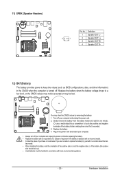
... Headers) 4 1 Pin No. 1 2 3 4 Definition Speaker OUT LSpeaker OUT L+ Speaker OUT R+ Speaker OUT R- 12) BAT (Battery) The battery provides power to keep the values (such as BIOS configurations, date, and time information) in the CMOS when the computer is replaced with an incorrect model. • Contact the place of purchase or local...
... Headers) 4 1 Pin No. 1 2 3 4 Definition Speaker OUT LSpeaker OUT L+ Speaker OUT R+ Speaker OUT R- 12) BAT (Battery) The battery provides power to keep the values (such as BIOS configurations, date, and time information) in the CMOS when the computer is replaced with an incorrect model. • Contact the place of purchase or local...
Manual
Page 30
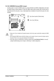
...13) CLR_CMOSHW (Clearing CMOS Jumper) Use this jumper to Chapter 2, "BIOS Setup," for a few seconds. Failure to do so may cause damage to the motherboard. • After system restart, go to BIOS Setup to load factory defaults (select Load Optimized Defaults) or manually configure ...the BIOS settings (refer to clear the CMOS values (e.g. Open: Normal operation (Default setting) Close: Clear CMOS ...
...13) CLR_CMOSHW (Clearing CMOS Jumper) Use this jumper to Chapter 2, "BIOS Setup," for a few seconds. Failure to do so may cause damage to the motherboard. • After system restart, go to BIOS Setup to load factory defaults (select Load Optimized Defaults) or manually configure ...the BIOS settings (refer to clear the CMOS values (e.g. Open: Normal operation (Default setting) Close: Clear CMOS ...
Manual
Page 31
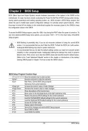
... Power-On Self-Test (POST) during the POST when the power is turned on the motherboard. BIOS Setup If this occurs, try to clear the CMOS values and reset the board to default values....to keep the configuration values in Chapter 1 for how to clear the CMOS values.) BIOS Setup Program Function Keys Move the selection bar to select an item Execute command or enter the submenu Main... Menu: Exit the BIOS Setup program Submenus: Exit current submenu Increase the numeric value or make changes Decrease the numeric...
... Power-On Self-Test (POST) during the POST when the power is turned on the motherboard. BIOS Setup If this occurs, try to clear the CMOS values and reset the board to default values....to keep the configuration values in Chapter 1 for how to clear the CMOS values.) BIOS Setup Program Function Keys Move the selection bar to select an item Execute command or enter the submenu Main... Menu: Exit the BIOS Setup program Submenus: Exit current submenu Increase the numeric value or make changes Decrease the numeric...
Manual
Page 32
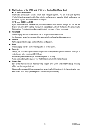
...default profile name, use the SPACE key) and then press to complete. F12: Load CMOS from BIOS If your system becomes unstable and you have loaded the BIOS default settings, you wish to load, then press to complete. Advanced This setup page includes all... Security Change, set, or disable supervisor and user password. You can also carry out this task.) Abandon all the items of AMI BIOS special enhanced features. (ex: Auto detect fan and temperature status, automatically configure hard disk parameters.) Chipset Northbridge and Southbridge additional features ...
...default profile name, use the SPACE key) and then press to complete. F12: Load CMOS from BIOS If your system becomes unstable and you have loaded the BIOS default settings, you wish to load, then press to complete. Advanced This setup page includes all... Security Change, set, or disable supervisor and user password. You can also carry out this task.) Abandon all the items of AMI BIOS special enhanced features. (ex: Auto detect fan and temperature status, automatically configure hard disk parameters.) Chipset Northbridge and Southbridge additional features ...
Manual
Page 33
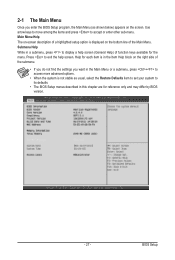
Submenu Help While in a submenu, press to display a help screen. BIOS Setup Press to exit the help screen (General Help) of function keys ...on-screen description of a highlighted setup option is displayed on the screen. 2-1 The Main Menu Once you enter the BIOS Setup program, the Main Menu (as shown below) appears on the bottom line of the submenu. • If you... Restore Defaults item to set your system to its defaults. • The BIOS Setup menus described in this chapter are for reference only and may differ by BIOS version. - 27 - Use arrow keys to move among the items and ...
Submenu Help While in a submenu, press to display a help screen. BIOS Setup Press to exit the help screen (General Help) of function keys ...on-screen description of a highlighted setup option is displayed on the screen. 2-1 The Main Menu Once you enter the BIOS Setup program, the Main Menu (as shown below) appears on the bottom line of the submenu. • If you... Restore Defaults item to set your system to its defaults. • The BIOS Setup menus described in this chapter are for reference only and may differ by BIOS version. - 27 - Use arrow keys to move among the items and ...
Manual
Page 34
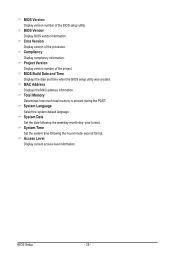
...total memory is present during the POST. System Language Select the system default language. year format. BIOS Vendor Display BIOS vendor information. second format. Project Version Display version number of the processor. MAC Address Displays the MAC address information.... BIOS Setup - 28 - Access Level Display current access level information. Compliency Display compliency information. BIOS Version Display version number of the BIOS setup utility. BIOS Build Date and Time Displays the date and time when ...
...total memory is present during the POST. System Language Select the system default language. year format. BIOS Vendor Display BIOS vendor information. second format. Project Version Display version number of the processor. MAC Address Displays the MAC address information.... BIOS Setup - 28 - Access Level Display current access level information. Compliency Display compliency information. BIOS Version Display version number of the BIOS setup utility. BIOS Build Date and Time Displays the date and time when ...
Manual
Page 35
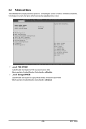
Select a submenu item, then press Enter to access the related submenu screen. Default setting is Enabled. - 29 - BIOS Setup Launch Storage OPROM Enable/Disable Boot Option for Legacy Mass Storage device with option ROM. 2-2 Advanced Menu The Advanced menu display submenu options for PXE device with option ROM. Options available: Enabled/Disabled. Default setting is Disabled. Launch PXE OPROM Enable/Disable Boot Option for configuring the function of various hardware components. Options available: Enabled/Disabled.
Select a submenu item, then press Enter to access the related submenu screen. Default setting is Enabled. - 29 - BIOS Setup Launch Storage OPROM Enable/Disable Boot Option for Legacy Mass Storage device with option ROM. 2-2 Advanced Menu The Advanced menu display submenu options for PXE device with option ROM. Options available: Enabled/Disabled. Default setting is Disabled. Launch PXE OPROM Enable/Disable Boot Option for configuring the function of various hardware components. Options available: Enabled/Disabled.
Manual
Page 36
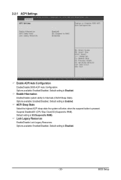
... Sleep State Select the highest ACPI sleep state the system will enter, when the suspend button is S3 (Suspend to RAM). Default setting is pressed. BIOS Setup Options available: Enabled/Disabled. Lock Legacy Resources Enable/Disable Lock Legacy Resources. Default setting is Enabled. Default setting is Disabled. - 30 - Options available: Enabled...
... Sleep State Select the highest ACPI sleep state the system will enter, when the suspend button is S3 (Suspend to RAM). Default setting is pressed. BIOS Setup Options available: Enabled/Disabled. Lock Legacy Resources Enable/Disable Lock Legacy Resources. Default setting is Enabled. Default setting is Disabled. - 30 - Options available: Enabled...
Manual
Page 38
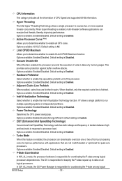
... (Note) Allows you to determine whether to enable all CPU cores. Options available: Enabled/Disabled. Default setting is responsible for coordinating the P-state among logical BIOS Setup - 32 - Options available: Enabled/Disabled. The OS is Enabled. Adjacent Cache Line Prefetch When enabled, cache lines are not multi-threaded or optimized for...
... (Note) Allows you to determine whether to enable all CPU cores. Options available: Enabled/Disabled. Default setting is responsible for coordinating the P-state among logical BIOS Setup - 32 - Options available: Enabled/Disabled. The OS is Enabled. Adjacent Cache Line Prefetch When enabled, cache lines are not multi-threaded or optimized for...
Manual
Page 39
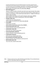
...When enabled, the CPU core frequency and voltage will be reduced during system halt state to determine desire values. Auto lets the BIOS automatically configure this feature. Default setting is ACPI C2. Default setting is HW_ALL. Factory long duration maintained Display the information of ... you install a CPU that supports this setting. Default setting is present only if you to determine whether to determine desire values. BIOS Setup - 33 - Options available: HW_ALL/SW_ALL/SW_ANY. Short duration power limit Press numeric keys to determine desire values. (Note) This item...
...When enabled, the CPU core frequency and voltage will be reduced during system halt state to determine desire values. Auto lets the BIOS automatically configure this feature. Default setting is ACPI C2. Default setting is HW_ALL. Factory long duration maintained Display the information of ... you install a CPU that supports this setting. Default setting is present only if you to determine whether to determine desire values. BIOS Setup - 33 - Options available: HW_ALL/SW_ALL/SW_ANY. Short duration power limit Press numeric keys to determine desire values. (Note) This item...
Manual
Page 40
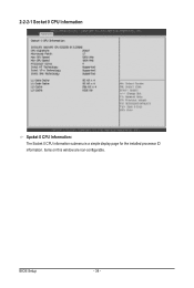
Items on this window are non-configurable. BIOS Setup - 34 - 2-2-2-1 Socket 0 CPU Information Spcket 0 CPU Information: The Socket 0 CPU information submenu is a simple display page for the installed processor ID information.
Items on this window are non-configurable. BIOS Setup - 34 - 2-2-2-1 Socket 0 CPU Information Spcket 0 CPU Information: The Socket 0 CPU information submenu is a simple display page for the installed processor ID information.
Manual
Page 41
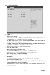
... information. - 35 - System will be labeled on chip SATA controller 0/1 mode. RAID Mode: When set to access RAID setup utility. Default setting is IDE Mode. BIOS Setup
... information. - 35 - System will be labeled on chip SATA controller 0/1 mode. RAID Mode: When set to access RAID setup utility. Default setting is IDE Mode. BIOS Setup
Manual
Page 42
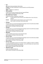
... particular IDE channel. The S.M.A.R.T. (Self Monitoring Analysis And Reporting) technology is Auto. Default setting is installed here. Option available: Auto/Disabled. Option available: Auto/Disabled. BIOS Setup - 36 - Block (Multi-Sector Transfer) Configure the information of the device in the specific IDE channel support LBA Mode. Option available: Auto/Disabled. S.M.A.R.T Mode...
... particular IDE channel. The S.M.A.R.T. (Self Monitoring Analysis And Reporting) technology is Auto. Default setting is installed here. Option available: Auto/Disabled. Option available: Auto/Disabled. BIOS Setup - 36 - Block (Multi-Sector Transfer) Configure the information of the device in the specific IDE channel support LBA Mode. Option available: Auto/Disabled. S.M.A.R.T Mode...
Manual
Page 44
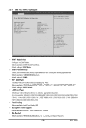
... OpRegion DVMT Mode Select Confiigure the DVMT Mode. Options available: 128MB/256MB/Maximum. Boot Type Select the Video Device that will be activated during POST. BIOS Setup Default setting is VBIOS Default. Options available: VBIOS Default/CRT/LFP/CRT+LFP/CRT+LFP - DVMT/Fixed Memory Select DVMT Pre-Allocated (Fixed) Graphics...
... OpRegion DVMT Mode Select Confiigure the DVMT Mode. Options available: 128MB/256MB/Maximum. Boot Type Select the Video Device that will be activated during POST. BIOS Setup Default setting is VBIOS Default. Options available: VBIOS Default/CRT/LFP/CRT+LFP/CRT+LFP - DVMT/Fixed Memory Select DVMT Pre-Allocated (Fixed) Graphics...

Manual
Page 45
BIOS Setup Spread Spectrum Clock Enable/Disabled Spread Spectrum Clock. Options available: VBIOS Default/NTSC-M/NTSC-J/NTSC-443/PAL-B/PAL-G/PAL-D/PAL-H/PAL-I/PAL-K/PAL-M/PAL-N/ PAL-Nc/SECAM-L/SECAM-B/SECAM-D/SECAM-G/SECAM-H/SECAM-K/1080i59/1080i60/ 33K 576i @50Hz/31K 576p @50Hz/ 1080i50/1080p50/720p59/720p60/480p60/480p59/480i60/480i59/1 080p60/1080p59/1080i60/1080i59 - 39 - Options available: Enabled/Disabled. Deafult setting is Disabled. TV Standard elect the TV standard used by the Internal graphics device.
BIOS Setup Spread Spectrum Clock Enable/Disabled Spread Spectrum Clock. Options available: VBIOS Default/NTSC-M/NTSC-J/NTSC-443/PAL-B/PAL-G/PAL-D/PAL-H/PAL-I/PAL-K/PAL-M/PAL-N/ PAL-Nc/SECAM-L/SECAM-B/SECAM-D/SECAM-G/SECAM-H/SECAM-K/1080i59/1080i60/ 33K 576i @50Hz/31K 576p @50Hz/ 1080i50/1080p50/720p59/720p60/480p60/480p59/480i60/480i59/1 080p60/1080p59/1080i60/1080i59 - 39 - Options available: Enabled/Disabled. Deafult setting is Disabled. TV Standard elect the TV standard used by the Internal graphics device.
Manual
Page 46
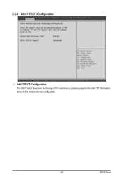
Items on this window are non-configurable. - 40 - BIOS Setup 2-2-6 Intel TXT(LT) Configuration Intel TXT(LT) Configuration The Intel Trusted Execution Technology (TXT) submenu is a display page for the Intel TXT information.
Items on this window are non-configurable. - 40 - BIOS Setup 2-2-6 Intel TXT(LT) Configuration Intel TXT(LT) Configuration The Intel Trusted Execution Technology (TXT) submenu is a display page for the Intel TXT information.


