Manual
Page 3
...the motherboard is exclusively licensed to their respective owners. Changes to the specifications and features in the use of this product, GIGABYTE provides the following types of documentations: „ For quick set-up of the product, read the Quick Installation Guide included...Support\Motherboard\Technology Guide page on your motherboard revision before updating motherboard BIOS, drivers, or when looking for technical information. Documentation Classifications In order to assist in this manual are legally registered to GIGABYTE UNITED INC. by GIGA-BYTE TECHNOLOGY CO., LTD as the ...
...the motherboard is exclusively licensed to their respective owners. Changes to the specifications and features in the use of this product, GIGABYTE provides the following types of documentations: „ For quick set-up of the product, read the Quick Installation Guide included...Support\Motherboard\Technology Guide page on your motherboard revision before updating motherboard BIOS, drivers, or when looking for technical information. Documentation Classifications In order to assist in this manual are legally registered to GIGABYTE UNITED INC. by GIGA-BYTE TECHNOLOGY CO., LTD as the ...
Manual
Page 4
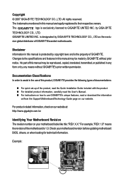
Table of Contents Box Contents ...6 OptionalItems ...6 GA-N650SLI-DS4L Motherboard Layout 7 Block Diagram ...8 Chapter 1 Hardware Installation 9 1-1 Installation Precautions 9 1-2 Product Specifications 10 1-3 Installing the CPU and CPU Cooler 13...an SLI (Scalable Link Interface) Configuration 19 1-7 Back Panel Connectors 22 1-8 Internal Connectors 24 Chapter 2 BIOS Setup 35 2-1 Startup Screen 36 2-2 The Main Menu 37 2-3 Standard CMOS Features 39 2-4 Advanced BIOS Features 41 2-5 IntegratedPeripherals 43 2-6 Power Management Setup 47 2-7 PnP/PCI Configurations 49 2-8 PC Health ...
Table of Contents Box Contents ...6 OptionalItems ...6 GA-N650SLI-DS4L Motherboard Layout 7 Block Diagram ...8 Chapter 1 Hardware Installation 9 1-1 Installation Precautions 9 1-2 Product Specifications 10 1-3 Installing the CPU and CPU Cooler 13...an SLI (Scalable Link Interface) Configuration 19 1-7 Back Panel Connectors 22 1-8 Internal Connectors 24 Chapter 2 BIOS Setup 35 2-1 Startup Screen 36 2-2 The Main Menu 37 2-3 Standard CMOS Features 39 2-4 Advanced BIOS Features 41 2-5 IntegratedPeripherals 43 2-6 Power Management Setup 47 2-7 PnP/PCI Configurations 49 2-8 PC Health ...

Manual
Page 5
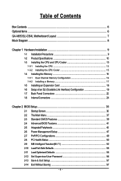
... 60 3-3 Driver CD Information 60 3-4 Hardware Information 61 3-5 Contact Us ...61 Chapter 4 Unique Features 63 4-1 Xpress Recovery2 63 4-2 BIOS Update Utilities 68 4-2-1 Updating the BIOS with the Q-Flash Utility 68 4-2-2 Updating the BIOS with the @BIOS Utility 71 4-3 EasyTune 5 ...73 4-4 Windows Vista ReadyBoost 74 Chapter 5 Appendix ...75 5-1 Configuring SATA Hard Drive(s 75 5-1-1 Configuring the...
... 60 3-3 Driver CD Information 60 3-4 Hardware Information 61 3-5 Contact Us ...61 Chapter 4 Unique Features 63 4-1 Xpress Recovery2 63 4-2 BIOS Update Utilities 68 4-2-1 Updating the BIOS with the Q-Flash Utility 68 4-2-2 Updating the BIOS with the @BIOS Utility 71 4-3 EasyTune 5 ...73 4-4 Windows Vista ReadyBoost 74 Chapter 5 Appendix ...75 5-1 Configuring SATA Hard Drive(s 75 5-1-1 Configuring the...
Manual
Page 8
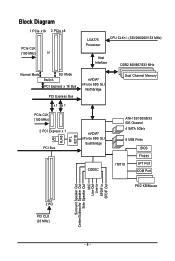
... Express x 1 PCI Bus LAN RJ45 RTL 8211B nVIDIA® nForce 650i SLI Southbridge CODEC ATA-133/100/66/33 IDE Channel 4 SATA 3Gb/s 8 USB Ports BIOS Floppy IT8718 LPT Port COM Port PS/2 KB/Mouse 2 PCI PCI CLK (33 MHz) Surround Speaker Out Center/Subwoofer Speaker Out Side Speaker Out MIC...
... Express x 1 PCI Bus LAN RJ45 RTL 8211B nVIDIA® nForce 650i SLI Southbridge CODEC ATA-133/100/66/33 IDE Channel 4 SATA 3Gb/s 8 USB Ports BIOS Floppy IT8718 LPT Port COM Port PS/2 KB/Mouse 2 PCI PCI CLK (33 MHz) Surround Speaker Out Center/Subwoofer Speaker Out Side Speaker Out MIC...
Manual
Page 12
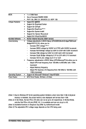
Adjust Memory frequency - GA-N650SLI-DS4L Motherboard - 12 - Increase North Bridge voltage by 0.025V to 0.775V with 0.05V increment - Increase DDR2 voltage by 0.05V to 0.35V with 0.025V increment - Adjust CPU ... on the CPU being used. Increase VCC12_DL voltage by 0.1V to 0.3V with 1 MHz increment Š Support for Virtual Dual BIOS Š Norton Internet Security (OEM version) Š Voltage adjustments in BIOS Setup (CPU/Memory/PCIe) allow you to 0.35V with 1 MHz increment - Increase South Bridge voltage by 0.1V or 0.2V Š...
Adjust Memory frequency - GA-N650SLI-DS4L Motherboard - 12 - Increase North Bridge voltage by 0.025V to 0.775V with 0.05V increment - Increase DDR2 voltage by 0.05V to 0.35V with 0.025V increment - Adjust CPU ... on the CPU being used. Increase VCC12_DL voltage by 0.1V to 0.3V with 1 MHz increment Š Support for Virtual Dual BIOS Š Norton Internet Security (OEM version) Š Voltage adjustments in BIOS Setup (CPU/Memory/PCIe) allow you to 0.35V with 1 MHz increment - Increase South Bridge voltage by 0.1V or 0.2V Š...
Manual
Page 16
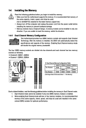
DS/SS - - Dual Channel mode cannot be installed in only one DDR2 memory module is installed, the BIOS will double the original memory bandwidth. When enabling Dual Channel mode with two or four memory modules, it is recommended that ... A memory module can be enabled if only one direction. If you begin to GIGABYTE's website for optimum performance. Enabling Dual Channel memory mode will automatically detect the specifications and capacity of the same capacity, brand, speed, and chips be used and installed in Dual Channel mode. 1. GA-N650SLI-DS4L Motherboard - 16 -
DS/SS - - Dual Channel mode cannot be installed in only one DDR2 memory module is installed, the BIOS will double the original memory bandwidth. When enabling Dual Channel mode with two or four memory modules, it is recommended that ... A memory module can be enabled if only one direction. If you begin to GIGABYTE's website for optimum performance. Enabling Dual Channel memory mode will automatically detect the specifications and capacity of the same capacity, brand, speed, and chips be used and installed in Dual Channel mode. 1. GA-N650SLI-DS4L Motherboard - 16 -
Manual
Page 18
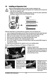
... is fully seated in the expansion slot. 1. After installing all expansion cards, replace the chassis cover(s). 6. Install the driver provided with a screw. 5. GA-N650SLI-DS4L Motherboard - 18 - • Removing the Card from the slot. Secure the card's metal bracket to the chassis back panel with the expansion card in ...an expansion slot that came with the slot, and press down on the top edge of the PCI Express x16 slot to make any required BIOS changes for your card. Turn on the card until it is fully inserted into the slot. 4. Example: Installing and Removing a PCI ...
... is fully seated in the expansion slot. 1. After installing all expansion cards, replace the chassis cover(s). 6. Install the driver provided with a screw. 5. GA-N650SLI-DS4L Motherboard - 18 - • Removing the Card from the slot. Secure the card's metal bracket to the chassis back panel with the expansion card in ...an expansion slot that came with the slot, and press down on the top edge of the PCI Express x16 slot to make any required BIOS changes for your card. Turn on the card until it is fully inserted into the slot. 4. Example: Installing and Removing a PCI ...
Manual
Page 29
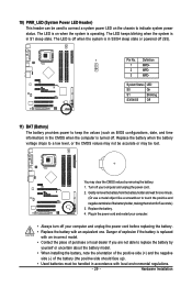
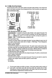
.... - 29 - System Status LED S0 On S1 Blinking S3/S4/S5 Off 11) BAT (Battery) The battery provides power to keep the values (such as BIOS configurations, date, and time information) in S1 sleep state. 10) PWR_LED (System Power LED Header) This header can be used to connect a system power LED...
.... - 29 - System Status LED S0 On S1 Blinking S3/S4/S5 Off 11) BAT (Battery) The battery provides power to keep the values (such as BIOS configurations, date, and time information) in S1 sleep state. 10) PWR_LED (System Power LED Header) This header can be used to connect a system power LED...
Manual
Page 30
...power switch (refer to Chapter 2, "BIOS Setup," "Power Management Setup," for information about beep codes. • HD (IDE Hard Drive Activity LED, Blue) Connects to this header according to the power status indicator on when the system is detected at system startup. GA-N650SLI-DS4L Motherboard - 30 - Note the ... different patterns to the speaker on the chassis front panel. If a problem is on the chassis front panel. The S0 On LED is detected, the BIOS may differ by issuing a beep code. PW+ PWSPEAK+ SPEAK- 2 20 1 19 HD+ HD- RESRES+ NC IDE Hard Disk Reset Active LED ...
...power switch (refer to Chapter 2, "BIOS Setup," "Power Management Setup," for information about beep codes. • HD (IDE Hard Drive Activity LED, Blue) Connects to this header according to the power status indicator on when the system is detected at system startup. GA-N650SLI-DS4L Motherboard - 30 - Note the ... different patterns to the speaker on the chassis front panel. If a problem is on the chassis front panel. The S0 On LED is detected, the BIOS may differ by issuing a beep code. PW+ PWSPEAK+ SPEAK- 2 20 1 19 HD+ HD- RESRES+ NC IDE Hard Disk Reset Active LED ...
Manual
Page 34
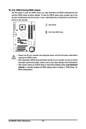
date information and BIOS configurations) and reset the CMOS values to clear the CMOS values (e.g. GA-N650SLI-DS4L Motherboard - 34 - To clear the CMOS values, place a jumper cap on your computer and unplug the power cord from the power outlet before clearing...temporarily short the two pins or use a metal object like a screwdriver to touch the two pins for BIOS configurations). Open: Normal Short: Clear CMOS Values • Always turn off your computer, be sure to Chapter 2, "BIOS Setup," for a few seconds. 19) CLR_CMOS (Clearing CMOS Jumper) Use this jumper to factory defaults....
date information and BIOS configurations) and reset the CMOS values to clear the CMOS values (e.g. GA-N650SLI-DS4L Motherboard - 34 - To clear the CMOS values, place a jumper cap on your computer and unplug the power cord from the power outlet before clearing...temporarily short the two pins or use a metal object like a screwdriver to touch the two pins for BIOS configurations). Open: Normal Short: Clear CMOS Values • Always turn off your computer, be sure to Chapter 2, "BIOS Setup," for a few seconds. 19) CLR_CMOS (Clearing CMOS Jumper) Use this jumper to factory defaults....
Manual
Page 35
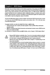
... the CMOS values.) - 35 - BIOS includes a BIOS Setup program that you not alter the default settings (unless you can press + in the main menu of the BIOS Setup program. For instructions on . To upgrade the BIOS, use either the GIGABYTE Q-Flash or @BIOS utility. • Q-Flash allows the... user to quickly and easily upgrade or back up BIOS without entering the operating system. • @BIOS is turned off, the battery ...
... the CMOS values.) - 35 - BIOS includes a BIOS Setup program that you not alter the default settings (unless you can press + in the main menu of the BIOS Setup program. For instructions on . To upgrade the BIOS, use either the GIGABYTE Q-Flash or @BIOS utility. • Q-Flash allows the... user to quickly and easily upgrade or back up BIOS without entering the operating system. • @BIOS is turned off, the battery ...
Manual
Page 36
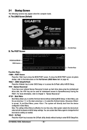
....00PG, An Energy Star Ally Copyright (C) 1984-2007, Award Software, Inc. A. GA-N650SLI-DS4L D1 . . . . : BIOS Setup/Q-Flash : XpressRecovery2 : Boot Menu : Qflash 09/20/2007-C55-MCP51-6A61IG04C-00 Function Keys Function Keys: : POST Screen Press...during the POST. The system will still be used for one time only. GA-N650SLI-DS4L Motherboard - 36 - To exit Boot Menu, press . 2-1 Startup Screen The following screens may appear when the computer boots. The LOGO Screen (Default) : POST Screen : BIOS Setup/Q-Flash : XpressRecovery2 : Boot Menu : Qflash B. For more information, ...
....00PG, An Energy Star Ally Copyright (C) 1984-2007, Award Software, Inc. A. GA-N650SLI-DS4L D1 . . . . : BIOS Setup/Q-Flash : XpressRecovery2 : Boot Menu : Qflash 09/20/2007-C55-MCP51-6A61IG04C-00 Function Keys Function Keys: : POST Screen Press...during the POST. The system will still be used for one time only. GA-N650SLI-DS4L Motherboard - 36 - To exit Boot Menu, press . 2-1 Startup Screen The following screens may appear when the computer boots. The LOGO Screen (Default) : POST Screen : BIOS Setup/Q-Flash : XpressRecovery2 : Boot Menu : Qflash B. For more information, ...
Manual
Page 37
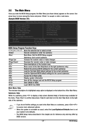
... screen. Press to exit the help screen (General Help) of the submenu. • If you do not find the settings you enter the BIOS Setup program, the Main Menu (as usual, select the Load Optimized Defaults item to set your system to display a help screen. Submenu Help ... of a highlighted setup option is in a submenu, press to its defaults. • The BIOS Setup menus described in this chapter are for reference only and may differ by BIOS version. - 37 - BIOS Setup Help for the current submenus Access the Q-Flash utility Display system information Save all the changes...
... screen. Press to exit the help screen (General Help) of the submenu. • If you do not find the settings you enter the BIOS Setup program, the Main Menu (as usual, select the Load Optimized Defaults item to set your system to display a help screen. Submenu Help ... of a highlighted setup option is in a submenu, press to its defaults. • The BIOS Setup menus described in this chapter are for reference only and may differ by BIOS version. - 37 - BIOS Setup Help for the current submenus Access the Q-Flash utility Display system information Save all the changes...
Manual
Page 38
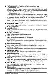
...temperature, system voltage and fan speed, etc. „ MB Intelligent Tweaker(M.I.T.) Use this menu to configure all changes and the previous settings remain in BIOS Setup. „ Set User Password Change, set , or disable password. A supervisor password allows you wish to load, then press to complete. ... restrict access to the system and BIOS Setup. „ The Functions of the and keys (For the Main Menu Only) ` F11: Save CMOS to BIOS This function allows you to restrict access to the system and BIOS Setup. You can use this task.) GA-N650SLI-DS4L Motherboard - 38 - It allows you...
...temperature, system voltage and fan speed, etc. „ MB Intelligent Tweaker(M.I.T.) Use this menu to configure all changes and the previous settings remain in BIOS Setup. „ Set User Password Change, set , or disable password. A supervisor password allows you wish to load, then press to complete. ... restrict access to the system and BIOS Setup. „ The Functions of the and keys (For the Main Menu Only) ` F11: Save CMOS to BIOS This function allows you to restrict access to the system and BIOS Setup. You can use this task.) GA-N650SLI-DS4L Motherboard - 38 - It allows you...
Manual
Page 39
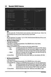
... hard drive access mode is set to set this item to autodetect the parameters of the two methods below : • Auto Lets BIOS automatically detect IDE/SATA devices during the POST for faster system startup. Sets the hard drive access mode. Extended IDE Drive Configure your ... Channel 2/3/4/5 Master IDE Auto-Detection Press to None so the system will • Manual skip the detection of the IDE/SATA device on this channel. BIOS Setup Options are : Auto (default), CHS, LBA, Large. For example, 1 p.m. IDE Channel 0 Master/Slave IDE HDD Auto-Detection Press to autodetect...
... hard drive access mode is set to set this item to autodetect the parameters of the two methods below : • Auto Lets BIOS automatically detect IDE/SATA devices during the POST for faster system startup. Sets the hard drive access mode. Extended IDE Drive Configure your ... Channel 2/3/4/5 Master IDE Auto-Detection Press to None so the system will • Manual skip the detection of the IDE/SATA device on this channel. BIOS Setup Options are : Auto (default), CHS, LBA, Large. For example, 1 p.m. IDE Channel 0 Master/Slave IDE HDD Auto-Detection Press to autodetect...
Manual
Page 40
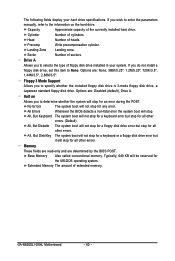
... 360K/5.25", 1.2M/5.25", 720K/3.5", 1.44M/3.5", 2.88M/3.5". Landing Zone Landing zone. Sector Number of cylinders. Options are determined by the BIOS POST. Typically, 640 KB will not stop for all other errors. Cylinder Number of sectors. Floppy 3 Mode Support Allows you do not ... of the currently installed hard drive. All Errors Whenever the BIOS detects a non-fatal error the system boot will stop for a keyboard or a floppy disk drive error but stop for an error during the POST. GA-N650SLI-DS4L Motherboard - 40 - Options are: Disabled (default), Drive ...
... 360K/5.25", 1.2M/5.25", 720K/3.5", 1.44M/3.5", 2.88M/3.5". Landing Zone Landing zone. Sector Number of cylinders. Options are determined by the BIOS POST. Typically, 640 KB will not stop for all other errors. Cylinder Number of sectors. Floppy 3 Mode Support Allows you do not ... of the currently installed hard drive. All Errors Whenever the BIOS detects a non-fatal error the system boot will stop for a keyboard or a floppy disk drive error but stop for an error during the POST. GA-N650SLI-DS4L Motherboard - 40 - Options are: Disabled (default), Drive ...
Manual
Page 41
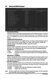
... allows your hard drive. Enabled Enables all CPU cores and multi-threading function when using an Intel® CPU that supports multi-core technology. BIOS Setup to 3 (Note) No-Execute Memory Protect (Note) CPU Enhanced Halt (C1E) (Note) CPU Thermal Monitor 2(TM2) (Note) CPU...This item is required for booting the system and for operating systems that supports this feature. Setup A password is only required for entering the BIOS Setup program. (Default) System A password is present only if you install a CPU that support multi-processor mode. Capability Enables or disables ...
... allows your hard drive. Enabled Enables all CPU cores and multi-threading function when using an Intel® CPU that supports multi-core technology. BIOS Setup to 3 (Note) No-Execute Memory Protect (Note) CPU Enhanced Halt (C1E) (Note) CPU Thermal Monitor 2(TM2) (Note) CPU...This item is required for booting the system and for operating systems that supports this feature. Setup A password is only required for entering the BIOS Setup program. (Default) System A password is present only if you install a CPU that support multi-processor mode. Capability Enables or disables ...
Manual
Page 43
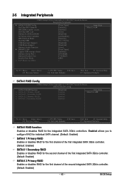
... first channel of the first integrated SATA 3Gb/s controller. (Default: Enabled) SATA-II 2 Primary RAID Enables or disables RAID for the integrated SATA 3Gb/s controllers. BIOS Setup
... first channel of the first integrated SATA 3Gb/s controller. (Default: Enabled) SATA-II 2 Primary RAID Enables or disables RAID for the integrated SATA 3Gb/s controllers. BIOS Setup
Manual
Page 45
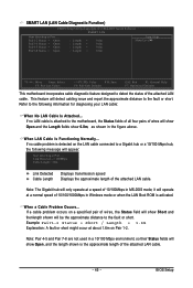
... Is Functioning Normally... Link Detected --> 100Mbps Cable Length= 30m Link Detected Cable Length Displays transmission speed Displays the approximate length of the attached LAN cable. BIOS Setup SMART LAN (LAN Cable Diagnostic Function) CMOS Setup Utility-Copyright (C) 1984-2007 Award Software SMART LAN Start detecting at about 1.6m on Pair 1-2.
... Is Functioning Normally... Link Detected --> 100Mbps Cable Length= 30m Link Detected Cable Length Displays transmission speed Displays the approximate length of the attached LAN cable. BIOS Setup SMART LAN (LAN Cable Diagnostic Function) CMOS Setup Utility-Copyright (C) 1984-2007 Award Software SMART LAN Start detecting at about 1.6m on Pair 1-2.
Manual
Page 47
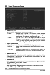
... in a low power mode. S1(POS) Enables the system to turn off the system. In S3 sleep state, the system appears to RAM) sleep state. BIOS Setup If the power button is pressed for 4 seconds to enter the ACPI S1 (Power on Windows® Vista® operating system only. - 47 -
... in a low power mode. S1(POS) Enables the system to turn off the system. In S3 sleep state, the system appears to RAM) sleep state. BIOS Setup If the power button is pressed for 4 seconds to enter the ACPI S1 (Power on Windows® Vista® operating system only. - 47 -


