Manual
Page 1
GA-N650SLI-DS4L LGA775 socket motherboard for Intel® CoreTM processor family/ Intel® Pentium® processor family/Intel® Celeron® processor family User's Manual Rev. 1001 12ME-N650DS4L-1001R
GA-N650SLI-DS4L LGA775 socket motherboard for Intel® CoreTM processor family/ Intel® Pentium® processor family/Intel® Celeron® processor family User's Manual Rev. 1001 12ME-N650DS4L-1001R
Manual
Page 3
... GIGA-BYTE TECHNOLOGY CO., LTD as the exclu- No part of GIGABYTE branded motherboards. For product-related information, check on our website at: http://www.gigabyte.com.tw Identifying Your Motherboard Revision The revision number on our website. Check your motherboard looks like this product, GIGABYTE provides the following types of documentations: „ For quick set...
... GIGA-BYTE TECHNOLOGY CO., LTD as the exclu- No part of GIGABYTE branded motherboards. For product-related information, check on our website at: http://www.gigabyte.com.tw Identifying Your Motherboard Revision The revision number on our website. Check your motherboard looks like this product, GIGABYTE provides the following types of documentations: „ For quick set...
Manual
Page 4
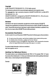
Table of Contents Box Contents ...6 OptionalItems ...6 GA-N650SLI-DS4L Motherboard Layout 7 Block Diagram ...8 Chapter 1 Hardware Installation 9 1-1 Installation Precautions 9 1-2 Product Specifications 10 1-3 Installing the CPU and CPU Cooler 13 1-3-1 Installing the CPU 13 1-3-2 Installing the CPU ...
Table of Contents Box Contents ...6 OptionalItems ...6 GA-N650SLI-DS4L Motherboard Layout 7 Block Diagram ...8 Chapter 1 Hardware Installation 9 1-1 Installation Precautions 9 1-2 Product Specifications 10 1-3 Installing the CPU and CPU Cooler 13 1-3-1 Installing the CPU 13 1-3-2 Installing the CPU ...
Manual
Page 6
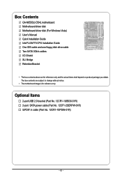
... Contents GA-N650SLI-DS4L motherboard Motherboard driver disk Motherboard driver disk (For Windows Vista) User's Manual Quick Installation Guide Intel® LGA775 CPU Installation Guide One IDE cable and one floppy disk drive cable Two SATA 3Gb/s cables I/O Shield SLI Bridge Retention Bracket • The box contents above are subject to change without notice. • The motherboard...
... Contents GA-N650SLI-DS4L motherboard Motherboard driver disk Motherboard driver disk (For Windows Vista) User's Manual Quick Installation Guide Intel® LGA775 CPU Installation Guide One IDE cable and one floppy disk drive cable Two SATA 3Gb/s cables I/O Shield SLI Bridge Retention Bracket • The box contents above are subject to change without notice. • The motherboard...
Manual
Page 9
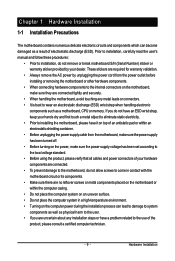
..., please verify that all cables and power connectors of your dealer. Hardware Installation Chapter 1 Hardware Installation 1-1 Installation Precautions The motherboard contains numerous delicate electronic circuits and components which can lead to damage to system components as well as physical harm to the ...: • Prior to installation, do not allow screws to come in a high-temperature environment. • Turning on the motherboard, make sure the power supply voltage has been set according to wear an electrostatic discharge (ESD) wrist strap when handling electronic components...
..., please verify that all cables and power connectors of your dealer. Hardware Installation Chapter 1 Hardware Installation 1-1 Installation Precautions The motherboard contains numerous delicate electronic circuits and components which can lead to damage to system components as well as physical harm to the ...: • Prior to installation, do not allow screws to come in a high-temperature environment. • Turning on the motherboard, make sure the power supply voltage has been set according to wear an electrostatic discharge (ESD) wrist strap when handling electronic components...
Manual
Page 10
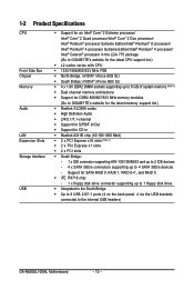
...system memory (Note 1) Š Dual channel memory architecture Š Support for DDR2 800/667/533 MHz memory modules (Go to GIGABYTE's website for the latest memory support list.) Š Realtek ALC888 codec Š High Definition Audio Š 2/4/5.1/7.1-channel Š ...GIGABYTE's website for the latest CPU support list.) Š L2 cache varies with CPU Š 1333/1066/800/533 MHz FSB Š North Bridge: nVIDIA® nForce 650i SLI Š South Bridge: nVIDIA® nForce 650i SLI Š 4 x 1.8V DDR2 DIMM sockets supporting up to the internal USB headers) GA-N650SLI-DS4L Motherboard...
...system memory (Note 1) Š Dual channel memory architecture Š Support for DDR2 800/667/533 MHz memory modules (Go to GIGABYTE's website for the latest memory support list.) Š Realtek ALC888 codec Š High Definition Audio Š 2/4/5.1/7.1-channel Š ...GIGABYTE's website for the latest CPU support list.) Š L2 cache varies with CPU Š 1333/1066/800/533 MHz FSB Š North Bridge: nVIDIA® nForce 650i SLI Š South Bridge: nVIDIA® nForce 650i SLI Š 4 x 1.8V DDR2 DIMM sockets supporting up to the internal USB headers) GA-N650SLI-DS4L Motherboard...
Manual
Page 12
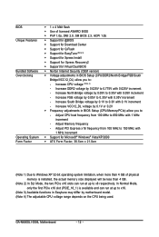
...the two PCIe x16 slots can run at up to x8 respectively. Adjust CPU host frequency from 100 MHz to 650 MHz with 0.1V increment - GA-N650SLI-DS4L Motherboard - 12 - Adjust PCI Express x16 frequency from 100 MHz to 150 MHz with 0.05V increment - Increase FSB voltage by 0.1V to : ...- Increase VCC12_DL voltage by 0.1V or 0.2V Š Frequency adjustments in Easytune may differ by motherboard model. (Note 4) The adjustable CPU voltage range depends on the CPU being used. In Normal Mode, only the first PCIe x16 slot (PCIE_16_1)...
...the two PCIe x16 slots can run at up to x8 respectively. Adjust CPU host frequency from 100 MHz to 650 MHz with 0.1V increment - GA-N650SLI-DS4L Motherboard - 12 - Adjust PCI Express x16 frequency from 100 MHz to 150 MHz with 0.05V increment - Increase FSB voltage by 0.1V to : ...- Increase VCC12_DL voltage by 0.1V or 0.2V Š Frequency adjustments in Easytune may differ by motherboard model. (Note 4) The adjustable CPU voltage range depends on the CPU being used. In Normal Mode, only the first PCIe x16 slot (PCIE_16_1)...
Manual
Page 13
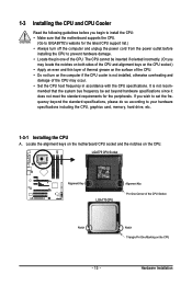
... 13 - LGA775 CPU Socket Alignment Key LGA 775 CPU Alignment Key Pin One Corner of the CPU. Locate the alignment keys on the motherboard CPU socket and the notches on the computer if the CPU cooler is not recom- The CPU cannot be set the frequency beyond hardware ...specifications since it does not meet the standard requirements for the peripherals. mended that the motherboard supports the CPU. (Go to GIGABYTE's website for the latest CPU support list.) • Always turn on the CPU. If you may occur. • Set ...
... 13 - LGA775 CPU Socket Alignment Key LGA 775 CPU Alignment Key Pin One Corner of the CPU. Locate the alignment keys on the motherboard CPU socket and the notches on the computer if the CPU cooler is not recom- The CPU cannot be set the frequency beyond hardware ...specifications since it does not meet the standard requirements for the peripherals. mended that the motherboard supports the CPU. (Go to GIGABYTE's website for the latest CPU support list.) • Always turn on the CPU. If you may occur. • Set ...
Manual
Page 14
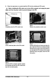
... CPU socket (or you may align the CPU notches with your thumb and index fingers. CPU Socket Lever Step 1: Completely raise the CPU socket lever. GA-N650SLI-DS4L Motherboard - 14 - Step 5: Once the CPU is properly inserted, replace the load plate and push the CPU socket lever back into position. B. Step 2: ...sure to turn off the computer and unplug the power cord from the power outlet to prevent damage to correctly install the CPU into the motherboard CPU socket. Step 4: Hold the CPU with the socket alignment keys) and gently insert the CPU into its locked position. Follow the steps...
... CPU socket (or you may align the CPU notches with your thumb and index fingers. CPU Socket Lever Step 1: Completely raise the CPU socket lever. GA-N650SLI-DS4L Motherboard - 14 - Step 5: Once the CPU is properly inserted, replace the load plate and push the CPU socket lever back into position. B. Step 2: ...sure to turn off the computer and unplug the power cord from the power outlet to prevent damage to correctly install the CPU into the motherboard CPU socket. Step 4: Hold the CPU with the socket alignment keys) and gently insert the CPU into its locked position. Follow the steps...
Manual
Page 15
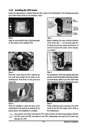
... 1: Apply an even and thin layer of thermal grease on installing the cooler.) Step 5: After the installation, check the back of the motherboard. Check that the Male and Female push pins are joined closely. (Refer to your CPU cooler installation manual for instructions on the surface of...the cooler atop the CPU, aligning the four push pins through the pin holes on the motherboard. 1-3-2 Installing the CPU Cooler Follow the steps below to correctly install the CPU cooler on the motherboard. (The following procedure uses Intel® boxed cooler as the picture above, the installation is...
... 1: Apply an even and thin layer of thermal grease on installing the cooler.) Step 5: After the installation, check the back of the motherboard. Check that the Male and Female push pins are joined closely. (Refer to your CPU cooler installation manual for instructions on the surface of...the cooler atop the CPU, aligning the four push pins through the pin holes on the motherboard. 1-3-2 Installing the CPU Cooler Follow the steps below to correctly install the CPU cooler on the motherboard. (The following procedure uses Intel® boxed cooler as the picture above, the installation is...
Manual
Page 16
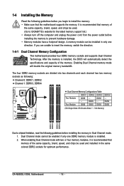
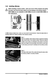
...be used . (Go to GIGABYTE's website for optimum performance. DS/SS DS/SS (SS=Single-Sided, DS=Double-Sided, "- -"=No Memory) DDRII1 DDRII2 DDRII3 DDRII4 Due to install the memory: • Make sure that the motherboard supports the memory. GA-N650SLI-DS4L Motherboard - 16 - After the...following guidelines before installing the memory to insert the memory, switch the direction. 1-4-1 Dual Channel Memory Configuration This motherboard provides four DDR2 memory sockets and supports Dual Channel Technology. Enabling Dual Channel memory mode will automatically detect the ...
...be used . (Go to GIGABYTE's website for optimum performance. DS/SS DS/SS (SS=Single-Sided, DS=Double-Sided, "- -"=No Memory) DDRII1 DDRII2 DDRII3 DDRII4 Due to install the memory: • Make sure that the motherboard supports the memory. GA-N650SLI-DS4L Motherboard - 16 - After the...following guidelines before installing the memory to insert the memory, switch the direction. 1-4-1 Dual Channel Memory Configuration This motherboard provides four DDR2 memory sockets and supports Dual Channel Technology. Enabling Dual Channel memory mode will automatically detect the ...
Manual
Page 17
... , make sure to turn off the computer and unplug the power cord from the power outlet to prevent damage to install DDR2 DIMMs on this motherboard. Follow the steps below to correctly install your fingers on the top edge of the memory module. As indicated in the picture on the socket...
... , make sure to turn off the computer and unplug the power cord from the power outlet to prevent damage to install DDR2 DIMMs on this motherboard. Follow the steps below to correctly install your fingers on the top edge of the memory module. As indicated in the picture on the socket...
Manual
Page 18
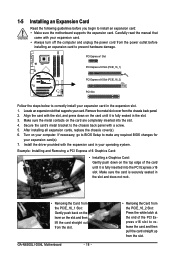
... the card and then pull the card straight up from the power outlet before you begin to install an expansion card: • Make sure the motherboard supports the expansion card. Make sure the card is fully inserted into the slot. 4. Remove the metal slot cover from the PCIE_16_2 Slot: Press the... Express x16 slot. 1-5 Installing an Expansion Card Read the following guidelines before installing an expansion card to prevent hardware damage. Align the card with a screw. 5. GA-N650SLI-DS4L Motherboard - 18 - • Removing the Card from the chassis back panel. 2.
... the card and then pull the card straight up from the power outlet before you begin to install an expansion card: • Make sure the motherboard supports the expansion card. Make sure the card is fully inserted into the slot. 4. Remove the metal slot cover from the PCIE_16_2 Slot: Press the... Express x16 slot. 1-5 Installing an Expansion Card Read the following guidelines before installing an expansion card to prevent hardware damage. Align the card with a screw. 5. GA-N650SLI-DS4L Motherboard - 18 - • Removing the Card from the chassis back panel. 2.
Manual
Page 20
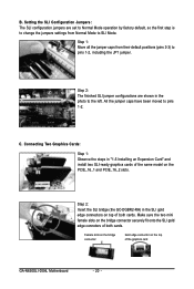
... gold edge connectors on top of the same model on the bridge connector securely fit onto the SLI gold edge connetors of the graphics card GA-N650SLI-DS4L Motherboard - 20 - Step 2: Insert the SLI bridge (the GC-DGBR2-RH) in the photo to pins 1-2. Step 1: Move all the jumper caps from Normal Mode to...
... gold edge connectors on top of the same model on the bridge connector securely fit onto the SLI gold edge connetors of the graphics card GA-N650SLI-DS4L Motherboard - 20 - Step 2: Insert the SLI bridge (the GC-DGBR2-RH) in the photo to pins 1-2. Step 1: Move all the jumper caps from Normal Mode to...
Manual
Page 21
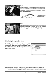
... panel with a screw. Step 3: In order to securely fix the bridge connector beween the two cards, you must install the retention bracket included with the motherboard and secure the retention bracket to the SLI configuration screen. Ensure SLI mode is enabled. (The SLI configuration screen may differ by driver version.) (Note...
... panel with a screw. Step 3: In order to securely fix the bridge connector beween the two cards, you must install the retention bracket included with the motherboard and secure the retention bracket to the SLI configuration screen. Ensure SLI mode is enabled. (The SLI configuration screen may differ by driver version.) (Note...
Manual
Page 22
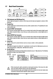
... your device and then remove it from the connector. Serial Port Use the serial port to an external audio system that supports digital coaxial audio. GA-N650SLI-DS4L Motherboard - 22 - The following describes the states of the LAN port LEDs. Do not rock it straight out from the... motherboard. • When removing the cable, pull it side to side to a back panel connector, first remove the cable from your audio system provides an optical ...
... your device and then remove it from the connector. Serial Port Use the serial port to an external audio system that supports digital coaxial audio. GA-N650SLI-DS4L Motherboard - 22 - The following describes the states of the LAN port LEDs. Do not rock it straight out from the... motherboard. • When removing the cable, pull it side to side to a back panel connector, first remove the cable from your audio system provides an optical ...
Manual
Page 24
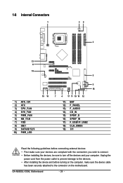
... 12) F_PANEL 13) F_AUDIO 14) CD_IN 15) SPDIF_O 16) SPDIF_IN 17) F_USB1/F_USB2 18) CLR_CMOS 19) CI1 Read the following guidelines before turning on the motherboard. Unplug the power cord from the power outlet to prevent damage to the devices. • After installing the device and before connecting external devices: •..., be sure to the connector on the computer, make sure the device cable has been securely attached to turn off the devices and your computer. GA-N650SLI-DS4L Motherboard - 24 -
... 12) F_PANEL 13) F_AUDIO 14) CD_IN 15) SPDIF_O 16) SPDIF_IN 17) F_USB1/F_USB2 18) CLR_CMOS 19) CI1 Read the following guidelines before turning on the motherboard. Unplug the power cord from the power outlet to prevent damage to the devices. • After installing the device and before connecting external devices: •..., be sure to the connector on the computer, make sure the device cable has been securely attached to turn off the devices and your computer. GA-N650SLI-DS4L Motherboard - 24 -
Manual
Page 25
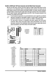
... power supply cable into pins under the protective cover when using a 2x12 power supply, remove the protective cover from the main power connector on the motherboard. When using a 2x10 power supply. 4 3 2 1 ATX_12V ATX_12V: Pin No. 1 2 3 4 Definition GND GND +12V +12V 12 24 1 13 ATX ATX: Pin No. 1 2 3... 25 - Before connecting the power connector, first make sure the power supply is turned off and all the components on the motherboard. Connect the power supply cable to the CPU. Hardware Installation The power connector possesses a foolproof design. If a power supply is...
... power supply cable into pins under the protective cover when using a 2x12 power supply, remove the protective cover from the main power connector on the motherboard. When using a 2x10 power supply. 4 3 2 1 ATX_12V ATX_12V: Pin No. 1 2 3 4 Definition GND GND +12V +12V 12 24 1 13 ATX ATX: Pin No. 1 2 3... 25 - Before connecting the power connector, first make sure the power supply is turned off and all the components on the motherboard. Connect the power supply cable to the CPU. Hardware Installation The power connector possesses a foolproof design. If a power supply is...
Manual
Page 26
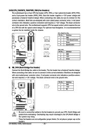
...+12V 3 NC • Be sure to connect fan cables to the fan headers to this header. 3/4/5) CPU_FAN/SYS_FAN/PWR_FAN (Fan Headers) The motherboard has a 4-pin CPU fan header (CPU_FAN), a 4-pin system fan header (SYS_FAN), and a 3-pin power fan header (PWR_FAN). For optimum ... the correct orientation. Do not place a jumper cap on the headers. The motherboard supports CPU fan speed control, which requires the use of a CPU fan with color-coded power connector wires. GA-N650SLI-DS4L Motherboard - 26 - When connecting a fan cable, be installed inside the chassis. ...
...+12V 3 NC • Be sure to connect fan cables to the fan headers to this header. 3/4/5) CPU_FAN/SYS_FAN/PWR_FAN (Fan Headers) The motherboard has a 4-pin CPU fan header (CPU_FAN), a 4-pin system fan header (SYS_FAN), and a 3-pin power fan header (PWR_FAN). For optimum ... the correct orientation. Do not place a jumper cap on the headers. The motherboard supports CPU fan speed control, which requires the use of a CPU fan with color-coded power connector wires. GA-N650SLI-DS4L Motherboard - 26 - When connecting a fan cable, be installed inside the chassis. ...
Manual
Page 28
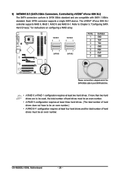
... the SATA 3Gb/s cable to be an even number.) • A RAID 0+1 configuration requires at least two hard drives. Each SATA connector supports a single SATA device. GA-N650SLI-DS4L Motherboard - 28 - 9) SATAII0/1/2/3 (SATA 3Gb/s Connectors, Controlled by nVIDIA® nForce 650i SLI) The SATA connectors conform to Chapter 5, "Configuring SATA Hard Drive(s)," for instructions on...
... the SATA 3Gb/s cable to be an even number.) • A RAID 0+1 configuration requires at least two hard drives. Each SATA connector supports a single SATA device. GA-N650SLI-DS4L Motherboard - 28 - 9) SATAII0/1/2/3 (SATA 3Gb/s Connectors, Controlled by nVIDIA® nForce 650i SLI) The SATA connectors conform to Chapter 5, "Configuring SATA Hard Drive(s)," for instructions on...


