
Manual
Page 3
... GIGA-BYTE TECHNOLOGY CO., LTD. The logo is 1.0. Documentation Classifications In order to use GIGABYTE's unique features, read or download the information on/from the Support\Motherboard\Technology Guide page on your motherboard revision before updating motherboard BIOS, drivers, or when looking for technical information. For product-related information, check on our...
... GIGA-BYTE TECHNOLOGY CO., LTD. The logo is 1.0. Documentation Classifications In order to use GIGABYTE's unique features, read or download the information on/from the Support\Motherboard\Technology Guide page on your motherboard revision before updating motherboard BIOS, drivers, or when looking for technical information. For product-related information, check on our...
Manual
Page 4
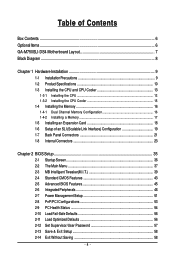
Table of Contents Box Contents ...6 OptionalItems ...6 GA-M750SLI-DS4 Motherboard Layout 7 Block Diagram ...8 Chapter 1 Hardware Installation 9 1-1 Installation Precautions 9 1-2 Product Specifications 10 1-3 Installing the CPU and CPU Cooler...Link Interface) Configuration 19 1-7 Back Panel Connectors 21 1-8 Internal Connectors 23 Chapter 2 BIOS Setup 35 2-1 Startup Screen 36 2-2 The Main Menu 37 2-3 MB Intelligent Tweaker(M.I.T 39 2-4 Standard CMOS Features 43 2-5 Advanced BIOS Features 45 2-6 IntegratedPeripherals 48 2-7 Power Management Setup 51 2-8 PnP/PCI Configurations 53 ...
Table of Contents Box Contents ...6 OptionalItems ...6 GA-M750SLI-DS4 Motherboard Layout 7 Block Diagram ...8 Chapter 1 Hardware Installation 9 1-1 Installation Precautions 9 1-2 Product Specifications 10 1-3 Installing the CPU and CPU Cooler...Link Interface) Configuration 19 1-7 Back Panel Connectors 21 1-8 Internal Connectors 23 Chapter 2 BIOS Setup 35 2-1 Startup Screen 36 2-2 The Main Menu 37 2-3 MB Intelligent Tweaker(M.I.T 39 2-4 Standard CMOS Features 43 2-5 Advanced BIOS Features 45 2-6 IntegratedPeripherals 48 2-7 Power Management Setup 51 2-8 PnP/PCI Configurations 53 ...

Manual
Page 5
... 60 3-3 Driver CD Information 60 3-4 Hardware Information 61 3-5 Contact Us ...61 Chapter 4 Unique Features 63 4-1 Xpress Recovery2 63 4-2 BIOS Update Utilities 68 4-2-1 Updating the BIOS with the Q-Flash Utility 68 4-2-2 Updating the BIOS with the @BIOS Utility 71 4-3 EasyTune 5 Pro 73 4-4 Windows Vista ReadyBoost 74 Chapter 5 Appendix ...75 5-1 Configuring SATA Hard Drive(s 75 5-1-1 Configuring...
... 60 3-3 Driver CD Information 60 3-4 Hardware Information 61 3-5 Contact Us ...61 Chapter 4 Unique Features 63 4-1 Xpress Recovery2 63 4-2 BIOS Update Utilities 68 4-2-1 Updating the BIOS with the Q-Flash Utility 68 4-2-2 Updating the BIOS with the @BIOS Utility 71 4-3 EasyTune 5 Pro 73 4-4 Windows Vista ReadyBoost 74 Chapter 5 Appendix ...75 5-1 Configuring SATA Hard Drive(s 75 5-1-1 Configuring...

Manual
Page 8
... D-Sub DVI-D NVIDIA® nForce® 750a SLI 6 SATA 3Gb/s 12 USB Ports CODEC ATA-133/100/66/33 IDE Channel LPC Bus IT8720 Dual BIOS Floppy LPT Port COM Port PS/2 KB or Mouse Surround Speaker Out Center/Subwoofer Speaker Out Side Speaker Out MIC Line-Out Line-In SPDIF...
... D-Sub DVI-D NVIDIA® nForce® 750a SLI 6 SATA 3Gb/s 12 USB Ports CODEC ATA-133/100/66/33 IDE Channel LPC Bus IT8720 Dual BIOS Floppy LPT Port COM Port PS/2 KB or Mouse Surround Speaker Out Center/Subwoofer Speaker Out Side Speaker Out MIC Line-Out Line-In SPDIF...
Manual
Page 12
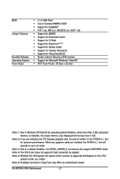
... Center Š Support for Q-Flash Š Support for EasyTune (Note 6) Š Support for Xpress Install Š Support for Xpress Recovery2 Š Support for Virtual Dual BIOS Š Norton Internet Security (OEM version) Š Support for optimum performance. When two graphics cards are installed, the PCIEX16_1 slot will depend on the CPU... fan speed control function is supported will operate at up to x8 mode. (Note 3) Due to install it in EasyTune may differ by motherboard model. GA-M750SLI-DS4 Motherboard - 12 -
... Center Š Support for Q-Flash Š Support for EasyTune (Note 6) Š Support for Xpress Install Š Support for Xpress Recovery2 Š Support for Virtual Dual BIOS Š Norton Internet Security (OEM version) Š Support for optimum performance. When two graphics cards are installed, the PCIEX16_1 slot will depend on the CPU... fan speed control function is supported will operate at up to x8 mode. (Note 3) Due to install it in EasyTune may differ by motherboard model. GA-M750SLI-DS4 Motherboard - 12 -
Manual
Page 16
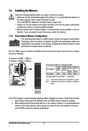
... Memory Configurations Table DDR2_1 DDR2_2 DDR2_3 DDR2_4 Two Modules DS/SS DS/SS - - - - - - - - GA-M750SLI-DS4 Motherboard - 16 - A memory module can be enabled if only one direction. After the memory is installed. 2. ...are to be used and installed in only one DDR2 memory module is installed, the BIOS will double the original memory bandwidth. If you install them in Dual Channel mode. ... capacity of the same capacity, brand, speed, and chips be used . (Go to GIGABYTE's website for optimum performance. The four DDR2 memory sockets are unable to insert the memory,...
... Memory Configurations Table DDR2_1 DDR2_2 DDR2_3 DDR2_4 Two Modules DS/SS DS/SS - - - - - - - - GA-M750SLI-DS4 Motherboard - 16 - A memory module can be enabled if only one direction. After the memory is installed. 2. ...are to be used and installed in only one DDR2 memory module is installed, the BIOS will double the original memory bandwidth. If you install them in Dual Channel mode. ... capacity of the same capacity, brand, speed, and chips be used . (Go to GIGABYTE's website for optimum performance. The four DDR2 memory sockets are unable to insert the memory,...
Manual
Page 18
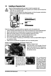
... the slot. 3. If necessary, go to BIOS Setup to make any required BIOS changes for your expansion card in the slot and does not rock. • Removing the Card: Press the white latch at the end of the card until it is fully seated in your computer. GA-M750SLI-DS4 Motherboard - 18 - • The motherboard...
... the slot. 3. If necessary, go to BIOS Setup to make any required BIOS changes for your expansion card in the slot and does not rock. • Removing the Card: Press the white latch at the end of the card until it is fully seated in your computer. GA-M750SLI-DS4 Motherboard - 18 - • The motherboard...
Manual
Page 28
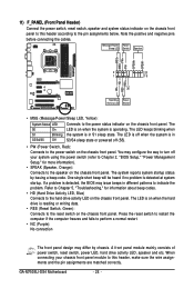
..., reset switch, power LED, hard drive activity LED, speaker and etc. When connecting your system using the power switch (refer to Chapter 2, "BIOS Setup," "Power Management Setup," for information about beep codes. • HD (Hard Drive Activity LED, Blue) Connects to turn off when the ...the power switch on when the system is in different patterns to the pin assignments below. The system reports system startup status by chassis. GA-M750SLI-DS4 Motherboard - 28 - Message/Power/ Power Sleep LED Switch Speaker MSG+ MSG- The LED is off your chassis front panel module to ...
..., reset switch, power LED, hard drive activity LED, speaker and etc. When connecting your system using the power switch (refer to Chapter 2, "BIOS Setup," "Power Management Setup," for information about beep codes. • HD (Hard Drive Activity LED, Blue) Connects to turn off when the ...the power switch on when the system is in different patterns to the pin assignments below. The system reports system startup status by chassis. GA-M750SLI-DS4 Motherboard - 28 - Message/Power/ Power Sleep LED Switch Speaker MSG+ MSG- The LED is off your chassis front panel module to ...

Manual
Page 33
...motherboard. • After system restart, go to BIOS Setup to load factory defaults (select Load Optimized Defaults) or manually configure the BIOS settings (refer to Chapter 2, "BIOS Setup," for a few seconds. Pin No. date information and BIOS configurations) and reset the CMOS values to remove ... like a screwdriver to clear the CMOS values (e.g. 20) CLR_CMOS (Clearing CMOS Jumper) Use this jumper to touch the two pins for BIOS configurations). 21) CI (Chassis Intrusion Header) This motherboard provides a chassis detection feature that detects if the chassis cover has been removed. ...
...motherboard. • After system restart, go to BIOS Setup to load factory defaults (select Load Optimized Defaults) or manually configure the BIOS settings (refer to Chapter 2, "BIOS Setup," for a few seconds. Pin No. date information and BIOS configurations) and reset the CMOS values to remove ... like a screwdriver to clear the CMOS values (e.g. 20) CLR_CMOS (Clearing CMOS Jumper) Use this jumper to touch the two pins for BIOS configurations). 21) CI (Chassis Intrusion Header) This motherboard provides a chassis detection feature that detects if the chassis cover has been removed. ...

Manual
Page 34
... Plug in accordance with an equivalent one minute. (Or use a metal object like a screwdriver to replace the battery by removing the battery: 1. GA-M750SLI-DS4 Motherboard - 34 - Danger of explosion if the battery is turned off. Replace the battery. 4. 22) BATTERY The battery provides power to a ...8226; Replace the battery with local environmental regulations. Replace the battery when the battery voltage drops to keep the values (such as BIOS configurations, date, and time information) in the CMOS when the computer is replaced with an incorrect model. • Contact the ...
... Plug in accordance with an equivalent one minute. (Or use a metal object like a screwdriver to replace the battery by removing the battery: 1. GA-M750SLI-DS4 Motherboard - 34 - Danger of explosion if the battery is turned off. Replace the battery. 4. 22) BATTERY The battery provides power to a ...8226; Replace the battery with local environmental regulations. Replace the battery when the battery voltage drops to keep the values (such as BIOS configurations, date, and time information) in the CMOS when the computer is replaced with an incorrect model. • Contact the ...

Manual
Page 35
... or to quickly and easily upgrade or back up BIOS without entering the operating system. • @BIOS is a Windows-based utility that searches and downloads the latest version of BIOS from the Internet and updates the BIOS. Inadequate BIOS flashing may result in system's failure to boot. ...to) to prevent system instability or other unexpected results. To upgrade the BIOS, use either the GIGABYTE Q-Flash or @BIOS utility. • Q-Flash allows the user to activate certain system features. To access the BIOS Setup program, press the key during the POST when the power is turned...
... or to quickly and easily upgrade or back up BIOS without entering the operating system. • @BIOS is a Windows-based utility that searches and downloads the latest version of BIOS from the Internet and updates the BIOS. Inadequate BIOS flashing may result in system's failure to boot. ...to) to prevent system instability or other unexpected results. To upgrade the BIOS, use either the GIGABYTE Q-Flash or @BIOS utility. • Q-Flash allows the user to activate certain system features. To access the BIOS Setup program, press the key during the POST when the power is turned...

Manual
Page 36
.... The system will still be used for one time only. A. The POST Screen Motherboard Model BIOS Version Award Modular BIOS v6.00PG, An Energy Star Ally Copyright (C) 1984-2008, Award Software, Inc. M750SLI-DS4 D28 . . . . : BIOS Setup : XpressRecovery2 : Boot Menu : Qflash 04/30/2008-NF-MCP78-6A61OG04C-00 Function Keys Function Keys: : POST Screen Press... Menu. After system restart, the device boot order will directly boot from the device configured in Boot Menu is effective for subsequent access to enter BIOS Setup first. GA-M750SLI-D4 Motherboard - 36 -
.... The system will still be used for one time only. A. The POST Screen Motherboard Model BIOS Version Award Modular BIOS v6.00PG, An Energy Star Ally Copyright (C) 1984-2008, Award Software, Inc. M750SLI-DS4 D28 . . . . : BIOS Setup : XpressRecovery2 : Boot Menu : Qflash 04/30/2008-NF-MCP78-6A61OG04C-00 Function Keys Function Keys: : POST Screen Press... Menu. After system restart, the device boot order will directly boot from the device configured in Boot Menu is effective for subsequent access to enter BIOS Setup first. GA-M750SLI-D4 Motherboard - 36 -

Manual
Page 37
... (General Help) of function keys available for the menu. Press to display a help screen. Help for reference only and may differ by BIOS version. - 37 - BIOS Setup BIOS Setup Program Function Keys Move the selection bar to select an item Execute command or enter the submenu Main Menu: Exit the... & Exit Setup Exit Without Saving ESC: Quit F8: Q-Flash KLJI: Select Item F10: Save & Exit Setup F11: Save CMOS to BIOS F12: Load CMOS from BIOS Main Menu Help The onscreen description of a highlighted setup option is in the Item Help block on the right side of the submenu...
... (General Help) of function keys available for the menu. Press to display a help screen. Help for reference only and may differ by BIOS version. - 37 - BIOS Setup BIOS Setup Program Function Keys Move the selection bar to select an item Execute command or enter the submenu Main Menu: Exit the... & Exit Setup Exit Without Saving ESC: Quit F8: Q-Flash KLJI: Select Item F10: Save & Exit Setup F11: Save CMOS to BIOS F12: Load CMOS from BIOS Main Menu Help The onscreen description of a highlighted setup option is in the Item Help block on the right side of the submenu...
Manual
Page 38
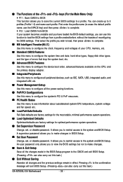
... message will exit BIOS Setup. (Pressing can also carry out this task.) „ Exit Without Saving Abandon all the power-saving functions. „ PnP/PCI Configurations Use this menu to configure the system's PCI & PnP resources. „ PC Health Status Use this task.) GA-M750SLI-D4 Motherboard - ...38 - „ The Functions of the and keys (For the Main Menu Only) ` F11 : Save CMOS to BIOS This function allows you to save the current BIOS settings to 8 profiles (Profile 1-8) and name each profile. ...
... message will exit BIOS Setup. (Pressing can also carry out this task.) „ Exit Without Saving Abandon all the power-saving functions. „ PnP/PCI Configurations Use this menu to configure the system's PCI & PnP resources. „ PC Health Status Use this task.) GA-M750SLI-D4 Motherboard - ...38 - „ The Functions of the and keys (For the Main Menu Only) ` F11 : Save CMOS to BIOS This function allows you to save the current BIOS settings to 8 profiles (Profile 1-8) and name each profile. ...

Manual
Page 39
...the CMOS values and reset the board to manually set the CPU host frequency. PCIE Clock Allows you to optimize the system voltage settings. BIOS Setup CPU Frequency Allows you to default values.) • When the System Voltage Optimized item blinks in red, it is dependent on the... set the PCIe clock frequency. Incorrectly doing overclock/overvoltage may result in damage to alter the clock ratio for the installed CPU. Auto BIOS will work stably with the CPU specifications. Important It is dependent on your overall system configurations. This page is from 100 MHz to...
...the CMOS values and reset the board to manually set the CPU host frequency. PCIE Clock Allows you to optimize the system voltage settings. BIOS Setup CPU Frequency Allows you to default values.) • When the System Voltage Optimized item blinks in red, it is dependent on the... set the PCIe clock frequency. Incorrectly doing overclock/overvoltage may result in damage to alter the clock ratio for the installed CPU. Auto BIOS will work stably with the CPU specifications. Important It is dependent on your overall system configurations. This page is from 100 MHz to...
Manual
Page 40
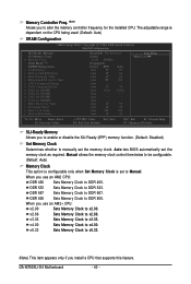
... RAS Active Time x 1T/2T Command Timing x TwTr Command Delay x Trfc0 for DIMM1 x Trfc2 for DIMM2 x Trfc1 for DIMM3 x Trfc3 for the installed CPU. Auto - - - - GA-M750SLI-D4 Motherboard - 40 - The adjustable range is set the memory clock as required. Memory Controller Freq. (Note) Allows you use an AM2+ CPU: x2.00... Auto 6T 6T Auto 6T 6T Auto 18T 18T Auto - - - - Auto 3T 3T Auto 105ns 105ns Auto - - - - Sets Memory Clock to x2.66. Auto lets BIOS automatically set to Manual. x2.66 x3.33 Sets Memory Clock to DDR 800.
... RAS Active Time x 1T/2T Command Timing x TwTr Command Delay x Trfc0 for DIMM1 x Trfc2 for DIMM2 x Trfc1 for DIMM3 x Trfc3 for the installed CPU. Auto - - - - GA-M750SLI-D4 Motherboard - 40 - The adjustable range is set the memory clock as required. Memory Controller Freq. (Note) Allows you use an AM2+ CPU: x2.00... Auto 6T 6T Auto 6T 6T Auto 18T 18T Auto - - - - Auto 3T 3T Auto 105ns 105ns Auto - - - - Sets Memory Clock to x2.66. Auto lets BIOS automatically set to Manual. x2.66 x3.33 Sets Memory Clock to DDR 800.

Manual
Page 41
... Command Delay Options are : 75ns, 105ns, 127.5ns, 195ns, 327.5ns. Trfc3 for DIMM2 Options are : Auto (default), 3T~6T. BIOS Setup Ganged Sets memory control mode to manually set memory control mode. RAS to CAS R/W Delay Options are : Auto (default), 3T~6T. Row... Command Timing Options are : 75ns, 105ns, 127.5ns, 195ns, 327.5ns. RAS to RAS Delay Options are : Auto (default), 11T~26T. Auto lets BIOS automatically set the system voltages as required. CAS# latency Options are : Auto (default), Manual. Options are : Auto (default), 3T~7T. Trfc0 for DIMM3 Options...
... Command Delay Options are : 75ns, 105ns, 127.5ns, 195ns, 327.5ns. Trfc3 for DIMM2 Options are : Auto (default), 3T~6T. BIOS Setup Ganged Sets memory control mode to manually set memory control mode. RAS to CAS R/W Delay Options are : Auto (default), 3T~6T. Row... Command Timing Options are : 75ns, 105ns, 127.5ns, 195ns, 327.5ns. RAS to RAS Delay Options are : Auto (default), 11T~26T. Auto lets BIOS automatically set the system voltages as required. CAS# latency Options are : Auto (default), Manual. Options are : Auto (default), 3T~7T. Trfc0 for DIMM3 Options...

Manual
Page 43
...None so the system will skip the detection of the two methods below : • Auto • None • Manual Access Mode Lets BIOS automatically detect IDE/SATA devices during the POST for faster system startup. IDE Channel 2, 3 Master/Slave IDE Auto-Detection Press to autodetect the parameters... of the IDE/SATA device on this item to manually enter the specifications of the three methods below : • Auto Lets BIOS automatically detect IDE/SATA devices during the POST for faster system startup. Extended IDE Drive Configure your IDE/SATA devices by using one ...
...None so the system will skip the detection of the two methods below : • Auto • None • Manual Access Mode Lets BIOS automatically detect IDE/SATA devices during the POST for faster system startup. IDE Channel 2, 3 Master/Slave IDE Auto-Detection Press to autodetect the parameters... of the IDE/SATA device on this item to manually enter the specifications of the three methods below : • Auto Lets BIOS automatically detect IDE/SATA devices during the POST for faster system startup. Extended IDE Drive Configure your IDE/SATA devices by using one ...

Manual
Page 44
... system boot will be reserved for any error. Typically, 640 KB will not stop for a keyboard or a floppy disk drive error but stop . GA-M750SLI-D4 Motherboard - 44 - Head Precomp Landing Zone Sector Number of cylinders. Write precompensation cylinder. Floppy 3 Mode Support Allows you do not install a ...-fatal error the system boot will stop for the MS-DOS operating system. Memory These fields are read-only and are determined by the BIOS POST. Cylinder Number of heads. The system boot will not stop for a keyboard error but stop for all other errors. Halt On ...
... system boot will be reserved for any error. Typically, 640 KB will not stop for a keyboard or a floppy disk drive error but stop . GA-M750SLI-D4 Motherboard - 44 - Head Precomp Landing Zone Sector Number of cylinders. Write precompensation cylinder. Floppy 3 Mode Support Allows you do not install a ...-fatal error the system boot will stop for the MS-DOS operating system. Memory These fields are read-only and are determined by the BIOS POST. Cylinder Number of heads. The system boot will not stop for a keyboard error but stop for all other errors. Halt On ...
Manual
Page 45
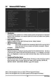
BIOS Setup Capability Away Mode Full Screen LOGO Show x Hybrid SLI (Note 2) x Display Detection (Note 2) Init Display First iGPU Frame Buffer Control x Frame Buffer Size Onboard ... press the plus key (or ) or the minus key (or ) to move it up or down on the list. 2-5 Advanced BIOS Features CMOS Setup Utility-Copyright (C) 1984-2008 Award Software Advanced BIOS Features Virtualization Patch AMD TLB Erratum (Note 1) AMD K8 Cool&Quiet control ` Hard Disk Boot Priority First Boot Device Second...
BIOS Setup Capability Away Mode Full Screen LOGO Show x Hybrid SLI (Note 2) x Display Detection (Note 2) Init Display First iGPU Frame Buffer Control x Frame Buffer Size Onboard ... press the plus key (or ) or the minus key (or ) to move it up or down on the list. 2-5 Advanced BIOS Features CMOS Setup Utility-Copyright (C) 1984-2008 Award Software Advanced BIOS Features Virtualization Patch AMD TLB Erratum (Note 1) AMD K8 Cool&Quiet control ` Hard Disk Boot Priority First Boot Device Second...


