Manual
Page 4
... ...6 GA-M750SLI-DS4 Motherboard Layout 7 Block Diagram ...8 Chapter 1 Hardware Installation 9 1-1 Installation Precautions 9 1-2 Product Specifications 10 1-3 Installing the CPU and CPU Cooler 13 1-3-1 Installing the CPU 13 1-3-2 Installing the CPU Cooler 15 1-4 Installing the Memory 16 1-4-1 Dual Channel Memory Configuration 16 1-4-2 Installing a Memory 17 1-5 Installing an Expansion Card 18 1-6 Setup of an SLI (Scalable Link Interface) Configuration 19 1-7 Back Panel Connectors 21 1-8 Internal Connectors 23 Chapter 2 BIOS Setup 35 2-1 Startup Screen 36 2-2 The Main Menu 37...
... ...6 GA-M750SLI-DS4 Motherboard Layout 7 Block Diagram ...8 Chapter 1 Hardware Installation 9 1-1 Installation Precautions 9 1-2 Product Specifications 10 1-3 Installing the CPU and CPU Cooler 13 1-3-1 Installing the CPU 13 1-3-2 Installing the CPU Cooler 15 1-4 Installing the Memory 16 1-4-1 Dual Channel Memory Configuration 16 1-4-2 Installing a Memory 17 1-5 Installing an Expansion Card 18 1-6 Setup of an SLI (Scalable Link Interface) Configuration 19 1-7 Back Panel Connectors 21 1-8 Internal Connectors 23 Chapter 2 BIOS Setup 35 2-1 Startup Screen 36 2-2 The Main Menu 37...
Manual
Page 10
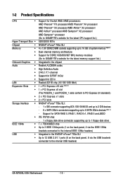
... SLI: - 1 x IDE connector supporting ATA-133/100/66/33 and up to 2 IDE devices - 6 x SATA 3Gb/s connectors supporting up to 6 SATA 3Gb/s devices (Note 3) - 1-2 Product Specifications CPU Š Hyper Transport Bus Š Chipset Š Memory Š Š Š Onboard Graphics Š Audio Š Š Š Š Š LAN Š Expansion Slots Š Š Š Š Storage Interface Š Š IEEE 1394a Š Š USB Š Š Support for Socket AM2+/AM2 processors: AMD PhenomTM FX processor/AMD PhenomTM X4 processor/ AMD...
... SLI: - 1 x IDE connector supporting ATA-133/100/66/33 and up to 2 IDE devices - 6 x SATA 3Gb/s connectors supporting up to 6 SATA 3Gb/s devices (Note 3) - 1-2 Product Specifications CPU Š Hyper Transport Bus Š Chipset Š Memory Š Š Š Onboard Graphics Š Audio Š Š Š Š Š LAN Š Expansion Slots Š Š Š Š Storage Interface Š Š IEEE 1394a Š Š USB Š Š Support for Socket AM2+/AM2 processors: AMD PhenomTM FX processor/AMD PhenomTM X4 processor/ AMD...
Manual
Page 12
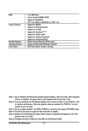
... installed, the actual memory size displayed will depend on the CPU/ system cooler you are installed, the PCIEX16_1 slot will operate at up to x8 mode. (Note 3) Due to install it in EasyTune may differ by adapter. (Note 5) Whether the CPU/system fan speed control function is supported will be sure to a chipset limitation, the SATA2_4/SATA2_5 connectors only support AHCI/RAID mode. (Note 4) The DVI-D port does not support D-Sub connection by motherboard model. BIOS...
... installed, the actual memory size displayed will depend on the CPU/ system cooler you are installed, the PCIEX16_1 slot will operate at up to x8 mode. (Note 3) Due to install it in EasyTune may differ by adapter. (Note 5) Whether the CPU/system fan speed control function is supported will be sure to a chipset limitation, the SATA2_4/SATA2_5 connectors only support AHCI/RAID mode. (Note 4) The DVI-D port does not support D-Sub connection by motherboard model. BIOS...
Manual
Page 16
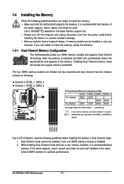
..., speed, and chips be used and installed in Dual Channel mode. 1. The four DDR2 memory sockets are unable to insert the memory, switch the direction. 1-4-1 Dual Channel Memory Configuration This motherboard provides four DDR2 memory sockets and supports Dual Channel Technology. If you install them in only one DDR2 memory module is installed, the BIOS will double the original memory bandwidth. A memory module can be enabled if only one direction. Dual Channel mode cannot be installed in the DDR2_1 and DDR2_2 sockets. 1-4 Installing the Memory Read...
..., speed, and chips be used and installed in Dual Channel mode. 1. The four DDR2 memory sockets are unable to insert the memory, switch the direction. 1-4-1 Dual Channel Memory Configuration This motherboard provides four DDR2 memory sockets and supports Dual Channel Technology. If you install them in only one DDR2 memory module is installed, the BIOS will double the original memory bandwidth. A memory module can be enabled if only one direction. Dual Channel mode cannot be installed in the DDR2_1 and DDR2_2 sockets. 1-4 Installing the Memory Read...
Manual
Page 18
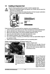
... driver provided with a screw. 5. Make sure the card is fully seated in the slot and does not rock. • Removing the Card: Press the white latch at the end of the card until it is fully inserted into the slot. 4. GA-M750SLI-DS4 Motherboard - 18 - • The motherboard provides a PCIE_12V power connector, which can supply extra power to the onboard PCI Express slots. Secure the card's metal bracket to the chassis back panel...
... driver provided with a screw. 5. Make sure the card is fully seated in the slot and does not rock. • Removing the Card: Press the white latch at the end of the card until it is fully inserted into the slot. 4. GA-M750SLI-DS4 Motherboard - 18 - • The motherboard provides a PCIE_12V power connector, which can supply extra power to the onboard PCI Express slots. Secure the card's metal bracket to the chassis back panel...
Manual
Page 20
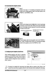
... SLI configuration screen may differ by driver version.) Procedure for more information about enabling SLI technology. Step 2: Insert the SLI bridge (the GC-DGBR2-RH) in "1-5 Installing an Expansion Card" and install two SLI-ready graphics cards of the same model on top of both cards. Browse to the NVIDIA Control Panel. Make sure the two mini female slots on the PCIEX16_1 slot.) C. B. Configuring the Graphics Card Driver: After installing graphics card driver in operating system, go to the SLI configuration screen. GA-M750SLI-DS4 Motherboard...
... SLI configuration screen may differ by driver version.) Procedure for more information about enabling SLI technology. Step 2: Insert the SLI bridge (the GC-DGBR2-RH) in "1-5 Installing an Expansion Card" and install two SLI-ready graphics cards of the same model on top of both cards. Browse to the NVIDIA Control Panel. Make sure the two mini female slots on the PCIEX16_1 slot.) C. B. Configuring the Graphics Card Driver: After installing graphics card driver in operating system, go to the SLI configuration screen. GA-M750SLI-DS4 Motherboard...
Manual
Page 25
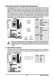
... connect fan cables to the fan headers to this connector when using two graphics cards. Most fans are not configuration jumper blocks. Do not place a jumper cap on the motherboard. Definition 1 NC 1 2 GND 3 GND 4 +12V - 25 - For optimum heat dissipation, it in damage to the CPU or the system may lead to the PCI Express slots on the headers. 6) PCIE_12V (Power Connector) This power connector can supply extra power to an unstable system. Each fan header supplies a +12V power voltage...
... connect fan cables to the fan headers to this connector when using two graphics cards. Most fans are not configuration jumper blocks. Do not place a jumper cap on the motherboard. Definition 1 NC 1 2 GND 3 GND 4 +12V - 25 - For optimum heat dissipation, it in damage to the CPU or the system may lead to the PCI Express slots on the headers. 6) PCIE_12V (Power Connector) This power connector can supply extra power to an unstable system. Each fan header supplies a +12V power voltage...
Manual
Page 38
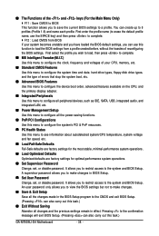
... CPU, memory, etc. „ Standard CMOS Features Use this menu to configure the system time and date, hard drive types, floppy disk drive types, and the type of errors that stop the system boot, etc. „ Advanced BIOS Features Use this menu to configure the device boot order, advanced features available on the CPU, and the primary display adapter. „ Integrated Peripherals Use this menu to configure all peripheral devices, such as IDE, SATA, USB, integrated audio, and integrated LAN, etc. „ Power Management Setup Use...
... CPU, memory, etc. „ Standard CMOS Features Use this menu to configure the system time and date, hard drive types, floppy disk drive types, and the type of errors that stop the system boot, etc. „ Advanced BIOS Features Use this menu to configure the device boot order, advanced features available on the CPU, and the primary display adapter. „ Integrated Peripherals Use this menu to configure all peripheral devices, such as IDE, SATA, USB, integrated audio, and integrated LAN, etc. „ Power Management Setup Use...
Manual
Page 40
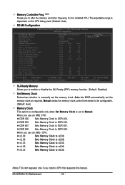
...-Safe Defaults ESC: Exit F1: General Help F7: Optimized Defaults SLI-Ready Memory Allows you to enable or disable the SLI-Ready (EPP) memory function. (Default: Disabled) Set Memory Clock Determines whether to DDR 667. Manual allows the memory clock control item below to be configurable. (Default: Auto) Memory Clock This option is configurable only when Set Memory Clock is dependent on the CPU being used. (Default: Auto) DRAM Configuration CMOS Setup Utility-Copyright (C) 1984-2008 Award Software DRAM Configuration SLI-Ready Memory Set Memory Clock x Memory Clock DCTs Mode (Note...
...-Safe Defaults ESC: Exit F1: General Help F7: Optimized Defaults SLI-Ready Memory Allows you to enable or disable the SLI-Ready (EPP) memory function. (Default: Disabled) Set Memory Clock Determines whether to DDR 667. Manual allows the memory clock control item below to be configurable. (Default: Auto) Memory Clock This option is configurable only when Set Memory Clock is dependent on the CPU being used. (Default: Auto) DRAM Configuration CMOS Setup Utility-Copyright (C) 1984-2008 Award Software DRAM Configuration SLI-Ready Memory Set Memory Clock x Memory Clock DCTs Mode (Note...
Manual
Page 45
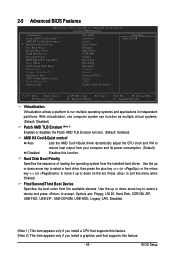
... BIOS Features CMOS Setup Utility-Copyright (C) 1984-2008 Award Software Advanced BIOS Features Virtualization Patch AMD TLB Erratum (Note 1) AMD K8 Cool&Quiet control ` Hard Disk Boot Priority First Boot Device Second Boot Device Third Boot Device Password Check HDD S.M.A.R.T. Capability Away Mode Full Screen LOGO Show x Hybrid SLI (Note 2) x Display Detection (Note 2) Init Display First iGPU Frame Buffer Control x Frame Buffer Size Onboard GPU [Disabled] [Enabled] [Auto] [Press Enter] [Floppy] [Hard Disk] [CDROM] [Setup] [Disabled] [Disabled] [Enabled] Disabled Enable [Onboard VGA] [Auto...
... BIOS Features CMOS Setup Utility-Copyright (C) 1984-2008 Award Software Advanced BIOS Features Virtualization Patch AMD TLB Erratum (Note 1) AMD K8 Cool&Quiet control ` Hard Disk Boot Priority First Boot Device Second Boot Device Third Boot Device Password Check HDD S.M.A.R.T. Capability Away Mode Full Screen LOGO Show x Hybrid SLI (Note 2) x Display Detection (Note 2) Init Display First iGPU Frame Buffer Control x Frame Buffer Size Onboard GPU [Disabled] [Enabled] [Auto] [Press Enter] [Floppy] [Hard Disk] [CDROM] [Setup] [Disabled] [Disabled] [Enabled] Disabled Enable [Onboard VGA] [Auto...
Manual
Page 46
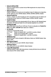
... boots, or only when you enter BIOS Setup. HDD S.M.A.R.T. Options are: 128M (default), 256M, 512M, Disabled. (Note 2) This item appears only if you to determine whether to manually set the password(s) under the Set Supervisor/User Password item in Windows XP Media Center operating system. GA-M750SLI-D4 Motherboard - 46 - After configuring this memory for the onboard graphics controller. Disabled displays normal POST message. (Default: Enabled) Hybrid SLI (Note 2) Enables or disables the Hybrid SLI function. (Default: Disabled) Display Detection (Note 2) Enabled...
... boots, or only when you enter BIOS Setup. HDD S.M.A.R.T. Options are: 128M (default), 256M, 512M, Disabled. (Note 2) This item appears only if you to determine whether to manually set the password(s) under the Set Supervisor/User Password item in Windows XP Media Center operating system. GA-M750SLI-D4 Motherboard - 46 - After configuring this memory for the onboard graphics controller. Disabled displays normal POST message. (Default: Enabled) Hybrid SLI (Note 2) Enables or disables the Hybrid SLI function. (Default: Disabled) Display Detection (Note 2) Enabled...
Manual
Page 48
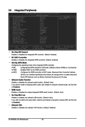
...GA-M750SLI-D4 Motherboard - 48 - IDE Configures the SATA controller to AHCI mode. Advanced Host Controller Interface (AHCI) is an interface specification that allows the storage driver to Disabled. 2-6 Integrated Peripherals CMOS Setup Utility-Copyright (C) 1984-2008 Award Software Integrated Peripherals On-Chip IDE Channel NV SATA Controller Onchip SATA Mode Onboard Audio Function HDMI Audio On-Chip MAC Lan Onboard 1394 ` SMART LAN Onboard LAN Boot ROM Onboard Serial Port 1 Onboard Parallel Port Parallel Port Mode x ECP Mode Use DMA On-Chip USB USB Memory Type USB Keyboard...
...GA-M750SLI-D4 Motherboard - 48 - IDE Configures the SATA controller to AHCI mode. Advanced Host Controller Interface (AHCI) is an interface specification that allows the storage driver to Disabled. 2-6 Integrated Peripherals CMOS Setup Utility-Copyright (C) 1984-2008 Award Software Integrated Peripherals On-Chip IDE Channel NV SATA Controller Onchip SATA Mode Onboard Audio Function HDMI Audio On-Chip MAC Lan Onboard 1394 ` SMART LAN Onboard LAN Boot ROM Onboard Serial Port 1 Onboard Parallel Port Parallel Port Mode x ECP Mode Use DMA On-Chip USB USB Memory Type USB Keyboard...
Manual
Page 50
...ECP Mode Use DMA Selects DMA channel for the LPT port in MS-DOS. (Default: Disabled) Legacy USB storage detect Determines whether to detect USB storage devices, including USB flash drives and USB hard drives during the POST. (Default: Enabled) GA-M750SLI-D4 Motherboard - 50 - Options are : Auto, 3F8/IRQ4 (default), 2F8/IRQ3, 3E8/IRQ4, 2E8/IRQ3, Disabled. Options are : SHADOW (default), Base Memory (640K). V1.1+V2.0 Enables the integrated USB 1.1 and USB 2.0 controllers. (Default) V1.1 Disabled Enables only the integrated USB 1.1 controller. Onboard Parallel Port Enables...
...ECP Mode Use DMA Selects DMA channel for the LPT port in MS-DOS. (Default: Disabled) Legacy USB storage detect Determines whether to detect USB storage devices, including USB flash drives and USB hard drives during the POST. (Default: Enabled) GA-M750SLI-D4 Motherboard - 50 - Options are : Auto, 3F8/IRQ4 (default), 2F8/IRQ3, 3E8/IRQ4, 2E8/IRQ3, Disabled. Options are : SHADOW (default), Base Memory (640K). V1.1+V2.0 Enables the integrated USB 1.1 and USB 2.0 controllers. (Default) V1.1 Disabled Enables only the integrated USB 1.1 controller. Onboard Parallel Port Enables...
Manual
Page 55
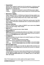
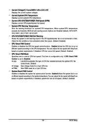
...) CPU Smart FAN Control Enables or disables the CPU fan speed control function. You can adjust the fan speed with EasyTune based on system requirements. Current Voltage(V) Vcore/DDR2 1.8V/+3.3V/+12V Displays the current system voltages. Current System/CPU Temperature Displays current system/CPU temperature. CPU/SYSTEM/POWER FAN Fail Warning Allows the system to emit warning sound if the CPU/system/power fan is set to the CPU temperature. Auto Voltage PWM Lets BIOS autodetect the type of CPU fan installed and sets the optimal CPU fan control mode. (Default) Sets Voltage mode...
...) CPU Smart FAN Control Enables or disables the CPU fan speed control function. You can adjust the fan speed with EasyTune based on system requirements. Current Voltage(V) Vcore/DDR2 1.8V/+3.3V/+12V Displays the current system voltages. Current System/CPU Temperature Displays current system/CPU temperature. CPU/SYSTEM/POWER FAN Fail Warning Allows the system to emit warning sound if the CPU/system/power fan is set to the CPU temperature. Auto Voltage PWM Lets BIOS autodetect the type of CPU fan installed and sets the optimal CPU fan control mode. (Default) Sets Voltage mode...
Manual
Page 69
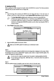
... Updating the BIOS When updating the BIOS, choose the location where the BIOS file is displayed on the screen. Step 1: 1. The monitor will display the update process. • Do not turn off or restart the system when the system is reading/updating the BIOS. • Do not remove the floppy disk, USB flash drive, or hard drive when the system is saved to a hard drive in RAID/AHCI mode or a hard drive attached to an independent IDE/SATA controller, use the key during the POST to update BIOS...
... Updating the BIOS When updating the BIOS, choose the location where the BIOS file is displayed on the screen. Step 1: 1. The monitor will display the update process. • Do not turn off or restart the system when the system is reading/updating the BIOS. • Do not remove the floppy disk, USB flash drive, or hard drive when the system is saved to a hard drive in RAID/AHCI mode or a hard drive attached to an independent IDE/SATA controller, use the key during the POST to update BIOS...
Manual
Page 75
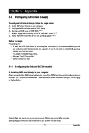
...formatted floppy disks. • Windows Vista/XP setup disk. • Motherboard driver disk. 5-1-1 Configuring the Onboard SATA Controller A. Configure SATA controller mode in RAID BIOS. (Note 1) D. Configure a RAID array in BIOS Setup. Installing SATA hard drive(s) in your power supply to the hard drive. (Note 1) Skip this step if you do not want to create RAID array on the motherboard. C . Install the SATA RAID/AHCI driver and operating system. (Note 2) Before you use two hard drives with identical model and capacity). Make a floppy disk containing the SATA RAID/AHCI driver...
...formatted floppy disks. • Windows Vista/XP setup disk. • Motherboard driver disk. 5-1-1 Configuring the Onboard SATA Controller A. Configure SATA controller mode in RAID BIOS. (Note 1) D. Configure a RAID array in BIOS Setup. Installing SATA hard drive(s) in your power supply to the hard drive. (Note 1) Skip this step if you do not want to create RAID array on the motherboard. C . Install the SATA RAID/AHCI driver and operating system. (Note 2) Before you use two hard drives with identical model and capacity). Make a floppy disk containing the SATA RAID/AHCI driver...
Manual
Page 80
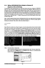
... the instructions below about how to exit this menu when all , copy the driver for the SATA controller from the motherboard driver disk during the Windows setup process. Step 1: Insert the prepared startup disk and motherboard driver disk in your optical drive folder, double click the MENU.exe file in MS-DOS mode . (Note) Prepare a startup disk that has CD-ROM support and two blank formatted floppy disks. Boot from the menu. At the D:\> prompt, type...
... the instructions below about how to exit this menu when all , copy the driver for the SATA controller from the motherboard driver disk during the Windows setup process. Step 1: Insert the prepared startup disk and motherboard driver disk in your optical drive folder, double click the MENU.exe file in MS-DOS mode . (Note) Prepare a startup disk that has CD-ROM support and two blank formatted floppy disks. Boot from the menu. At the D:\> prompt, type...
Manual
Page 81
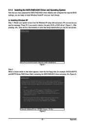
... BIOS settings, you are ready to install Windows Vista/XP onto your system, or you have any device support disks from a mass storage device manufacturer, or do not have chosen to manually specify an adapter. Currently, Setup will be a few moments of one or more mass storage devices installed in your hard drive(s). 5-1-3 Installing the SATA RAID/AHCI Driver and Operating System Now that below appears, insert the first floppy disk (for use with Windows...
... BIOS settings, you are ready to install Windows Vista/XP onto your system, or you have any device support disks from a mass storage device manufacturer, or do not have chosen to manually specify an adapter. Currently, Setup will be a few moments of one or more mass storage devices installed in your hard drive(s). 5-1-3 Installing the SATA RAID/AHCI Driver and Operating System Now that below appears, insert the first floppy disk (for use with Windows...
Manual
Page 82
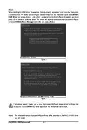
...-ROM drives, or special disk controllers for use with Windows, including those for which you have a device support disk from the motherboard driver disk. (Note) The selectable item(s) displayed in Figure 3 may differ according to the RAID or AHCI driver you must press to that in Figure 3 below will return to select NVIDIA RAID Driver and press . GA-M750SLI-DS4 Motherboard - 82 - NVIDIA RAID Driver (required) NVIDIA nForce Storage Controller (required) ENTER=Select F3=Exit Figure 3 Windows Setup Setup will install...
...-ROM drives, or special disk controllers for use with Windows, including those for which you have a device support disk from the motherboard driver disk. (Note) The selectable item(s) displayed in Figure 3 may differ according to the RAID or AHCI driver you must press to that in Figure 3 below will return to select NVIDIA RAID Driver and press . GA-M750SLI-DS4 Motherboard - 82 - NVIDIA RAID Driver (required) NVIDIA nForce Storage Controller (required) ENTER=Select F3=Exit Figure 3 Windows Setup Setup will install...
Manual
Page 94
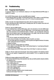
... Award BIOS beep code descriptions may help you identify possible computer problems. (For reference only.) 1 short: System boots successfully 2 short: CMOS setting error 1 long, 1 short: Memory or motherboard error 1 long, 2 short: Monitor or graphics card error 1 long, 3 short: Keyboard error 1 long, 9 short: BIOS ROM error Continuous long beeps: Graphics card not inserted properly Continuous short beeps: Power error GA-M750SLI-DS4 Motherboard - 94 - A: Some advanced options are some BIOS options missing? Q: Why is still on after the computer shuts down ? Gently remove the battery...
... Award BIOS beep code descriptions may help you identify possible computer problems. (For reference only.) 1 short: System boots successfully 2 short: CMOS setting error 1 long, 1 short: Memory or motherboard error 1 long, 2 short: Monitor or graphics card error 1 long, 3 short: Keyboard error 1 long, 9 short: BIOS ROM error Continuous long beeps: Graphics card not inserted properly Continuous short beeps: Power error GA-M750SLI-DS4 Motherboard - 94 - A: Some advanced options are some BIOS options missing? Q: Why is still on after the computer shuts down ? Gently remove the battery...


