
Manual
Page 9
... an ESD wrist strap, keep your hands dry and first touch a metal object to eliminate static electricity. • Prior to installing the motherboard, please have a problem related to the use of electrostatic discharge (ESD). Hardware Installation These stickers are required for warranty validation. • Always remove the AC power by your...
... an ESD wrist strap, keep your hands dry and first touch a metal object to eliminate static electricity. • Prior to installing the motherboard, please have a problem related to the use of electrostatic discharge (ESD). Hardware Installation These stickers are required for warranty validation. • Always remove the AC power by your...
Manual
Page 28
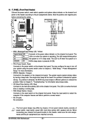
...connection The front panel design may differ by issuing a beep code. One single short beep will be heard if no problem is in different patterns to the power switch on the chassis front panel. 11) F_PANEL (Front Panel Header) Connect ... are matched correctly. The LED keeps blinking when S1 Blinking the system is detected at system startup. If a problem is reading or writing data. • RES (Reset Switch, Green): Connects to the reset switch on the ...status indicator on the chassis front panel. PW+ PWSPEAK+ SPEAK- 2 20 1 19 HD+ HD- GA-M750SLI-DS4 Motherboard - 28 -
...connection The front panel design may differ by issuing a beep code. One single short beep will be heard if no problem is in different patterns to the power switch on the chassis front panel. 11) F_PANEL (Front Panel Header) Connect ... are matched correctly. The LED keeps blinking when S1 Blinking the system is detected at system startup. If a problem is reading or writing data. • RES (Reset Switch, Green): Connects to the reset switch on the ...status indicator on the chassis front panel. PW+ PWSPEAK+ SPEAK- 2 20 1 19 HD+ HD- GA-M750SLI-DS4 Motherboard - 28 -

Manual
Page 35
...alter the default settings (unless you can press + in the main menu of the system in the CMOS. To upgrade the BIOS, use either the GIGABYTE Q-Flash or @BIOS utility. • Q-Flash allows the user to the "Load Optimized Defaults" section in system malfunction. • BIOS will emit...flash the BIOS. For instructions on the motherboard supplies the necessary power to the CMOS to boot. To flash the BIOS, do not encounter problems using the current version of BIOS, it with caution. Refer to Chapter 5, "Troubleshooting," for how to activate certain system features. To access...
...alter the default settings (unless you can press + in the main menu of the system in the CMOS. To upgrade the BIOS, use either the GIGABYTE Q-Flash or @BIOS utility. • Q-Flash allows the user to the "Load Optimized Defaults" section in system malfunction. • BIOS will emit...flash the BIOS. For instructions on the motherboard supplies the necessary power to the CMOS to boot. To flash the BIOS, do not encounter problems using the current version of BIOS, it with caution. Refer to Chapter 5, "Troubleshooting," for how to activate certain system features. To access...

Manual
Page 49
...Cable Diagnostic Function) CMOS Setup Utility-Copyright (C) 1984-2008 Award Software SMART LAN Start detecting at about 2m on Part 1-2. If no cable problem is detected on a specified pair of 10/100 Mbps in the figure above. Link Detected --> 100Mbps Cable Length= 30m Link Detected Cable Length... at Port..... This feature will be the approximate distance to detect the status of the attached LAN cable. When a Cable Problem Occurs... If a cable problem occurs on the LAN cable connected to the motherboard, the Status fields of all four pairs of the attached LAN cable. ...
...Cable Diagnostic Function) CMOS Setup Utility-Copyright (C) 1984-2008 Award Software SMART LAN Start detecting at about 2m on Part 1-2. If no cable problem is detected on a specified pair of 10/100 Mbps in the figure above. Link Detected --> 100Mbps Cable Length= 30m Link Detected Cable Length... at Port..... This feature will be the approximate distance to detect the status of the attached LAN cable. When a Cable Problem Occurs... If a cable problem occurs on the LAN cable connected to the motherboard, the Status fields of all four pairs of the attached LAN cable. ...
Manual
Page 94
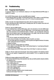
...problems. (For reference only.) 1 short: System boots successfully 2 short: CMOS setting error 1 long, 1 short: Memory or motherboard error 1 long, 2 short: Monitor or graphics card error 1 long, 3 short: Keyboard error 1 long, 9 short: BIOS ROM error Continuous long beeps: Graphics card not inserted properly Continuous short beeps: Power error GA-M750SLI-DS4... to show the advanced options. A: If your motherboard has a clearing CMOS jumper, refer to the instructions on GIGABYTE's website. If not, try a speaker with an internal amplifier. Select "Load Fail-Safe Defaults" (or "...
...problems. (For reference only.) 1 short: System boots successfully 2 short: CMOS setting error 1 long, 1 short: Memory or motherboard error 1 long, 2 short: Monitor or graphics card error 1 long, 3 short: Keyboard error 1 long, 9 short: BIOS ROM error Continuous long beeps: Graphics card not inserted properly Continuous short beeps: Power error GA-M750SLI-DS4... to show the advanced options. A: If your motherboard has a clearing CMOS jumper, refer to the instructions on GIGABYTE's website. If not, try a speaker with an internal amplifier. Select "Load Fail-Safe Defaults" (or "...

Manual
Page 95
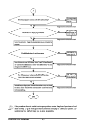
...motherboard. Connect the CPU cooler power cable to start the computer. A (Continued...) - 95 - Yes Isolate the short circuit. The problem is installed properly on the CPU. Press to the CPU_FAN header properly? Remove all peripherals, connecting cables, and power cord etc. Connect ... Is the power connector of the CPU cooler connected to enter BIOS Setup. Select "Save & Exit Setup" to solve the problem. 5-3-2 Troubleshooting Procedure If you encounter any troubles during system startup, follow the troubleshooting procedure below to save changes and exit BIOS...
...motherboard. Connect the CPU cooler power cable to start the computer. A (Continued...) - 95 - Yes Isolate the short circuit. The problem is installed properly on the CPU. Press to the CPU_FAN header properly? Remove all peripherals, connecting cables, and power cord etc. Connect ... Is the power connector of the CPU cooler connected to enter BIOS Setup. Select "Save & Exit Setup" to solve the problem. 5-3-2 Troubleshooting Procedure If you encounter any troubles during system startup, follow the troubleshooting procedure below to save changes and exit BIOS...
Manual
Page 96
... verified and solved. Select "Save & Exit Setup" to enter BIOS Setup. Turn off the computer. The problem is verified and solved. GA-M750SLI-DS4 Motherboard - 96 - The problem is verified and solved. No The keyboard or mouse might fail. No The graphics card, expansion slot, or monitor might fail....). Yes Turn off the computer and connect the IDE/SATA devices. Or go to the Support\Technical Service Zone page to submit your problem, contact the place of purchase or local dealer for help. No The IDE/SATA device, connector, or cable might fail. Yes Check...
... verified and solved. Select "Save & Exit Setup" to enter BIOS Setup. Turn off the computer. The problem is verified and solved. GA-M750SLI-DS4 Motherboard - 96 - The problem is verified and solved. No The keyboard or mouse might fail. No The graphics card, expansion slot, or monitor might fail....). Yes Turn off the computer and connect the IDE/SATA devices. Or go to the Support\Technical Service Zone page to submit your problem, contact the place of purchase or local dealer for help. No The IDE/SATA device, connector, or cable might fail. Yes Check...


