Manual
Page 1
GA-M750SLI-DS4 AM2+/AM2 socket motherboard for AMD PhenomTM FX processor/AMD PhenomTM X4 processor/ AMD PhenomTM X3 processor/AMD AthlonTM X2 processor/ AMD AthlonTM processor/AMD SempronTM X2 processor AMD SempronTM processor User's Manual Rev. 1002 12ME-M75SLID4-1002R
GA-M750SLI-DS4 AM2+/AM2 socket motherboard for AMD PhenomTM FX processor/AMD PhenomTM X4 processor/ AMD PhenomTM X3 processor/AMD AthlonTM X2 processor/ AMD AthlonTM processor/AMD SempronTM X2 processor AMD SempronTM processor User's Manual Rev. 1002 12ME-M75SLID4-1002R
Manual
Page 4
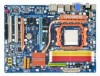
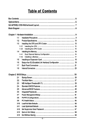
Table of Contents Box Contents ...6 OptionalItems ...6 GA-M750SLI-DS4 Motherboard Layout 7 Block Diagram ...8 Chapter 1 Hardware Installation 9 1-1 Installation Precautions 9 1-2 Product Specifications 10 1-3 Installing the CPU and CPU Cooler 13 1-3-1 Installing the CPU 13 1-3-2 Installing the ...
Table of Contents Box Contents ...6 OptionalItems ...6 GA-M750SLI-DS4 Motherboard Layout 7 Block Diagram ...8 Chapter 1 Hardware Installation 9 1-1 Installation Precautions 9 1-2 Product Specifications 10 1-3 Installing the CPU and CPU Cooler 13 1-3-1 Installing the CPU 13 1-3-2 Installing the ...
Manual
Page 6
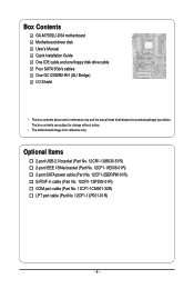
...) COM port cable (Part No. 12CF1-1CM001-32R) LPT port cable (Part No. 12CF1-1LP001-01R) - 6 - The box contents are for reference only. Box Contents GA-M750SLI-DS4 motherboard Motherboard driver disk User's Manual Quick Installation Guide One IDE cable and one floppy disk drive cable Four SATA 3Gb/s cables One GC-DGBR2...
...) COM port cable (Part No. 12CF1-1CM001-32R) LPT port cable (Part No. 12CF1-1LP001-01R) - 6 - The box contents are for reference only. Box Contents GA-M750SLI-DS4 motherboard Motherboard driver disk User's Manual Quick Installation Guide One IDE cable and one floppy disk drive cable Four SATA 3Gb/s cables One GC-DGBR2...
Manual
Page 10
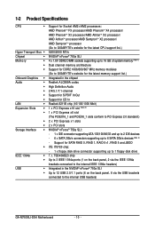
.../AMD PhenomTM X4 processor/ AMD PhenomTM X3 processor/AMD AthlonTM X2 processor/ AMD AthlonTM processor/AMD SempronTM X2 processor/ AMD SempronTM processor (Go to GIGABYTE's website for the latest CPU support list.) 5200/2000 MT/s NVIDIA® nForce® 750a SLI 4 x 1.8V DDR2 DIMM sockets supporting... 1066/800/667 MHz memory modules (Go to GIGABYTE's website for the latest memory support list.) Integrated in the NVIDIA® nForce® 750a SLI Up to 12 USB 2.0/1.1 ports (6 on the back panel, 6 via the USB brackets connected to the internal USB headers) GA-M750SLI-DS4 Motherboard - 10 -
.../AMD PhenomTM X4 processor/ AMD PhenomTM X3 processor/AMD AthlonTM X2 processor/ AMD AthlonTM processor/AMD SempronTM X2 processor/ AMD SempronTM processor (Go to GIGABYTE's website for the latest CPU support list.) 5200/2000 MT/s NVIDIA® nForce® 750a SLI 4 x 1.8V DDR2 DIMM sockets supporting... 1066/800/667 MHz memory modules (Go to GIGABYTE's website for the latest memory support list.) Integrated in the NVIDIA® nForce® 750a SLI Up to 12 USB 2.0/1.1 ports (6 on the back panel, 6 via the USB brackets connected to the internal USB headers) GA-M750SLI-DS4 Motherboard - 10 -
Manual
Page 12
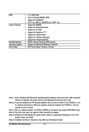
... you are installed, the PCIEX16_1 slot will operate at up to x8 mode. (Note 3) Due to install it in EasyTune may differ by motherboard model. GA-M750SLI-DS4 Motherboard - 12 - BIOS Unique Features Bundled Software Operating System Form Factor Š 2 x 8 Mbit flash Š Use of licensed AWARD BIOS Š Support for DualBIOSTM Š...
... you are installed, the PCIEX16_1 slot will operate at up to x8 mode. (Note 3) Due to install it in EasyTune may differ by motherboard model. GA-M750SLI-DS4 Motherboard - 12 - BIOS Unique Features Bundled Software Operating System Form Factor Š 2 x 8 Mbit flash Š Use of licensed AWARD BIOS Š Support for DualBIOSTM Š...
Manual
Page 14
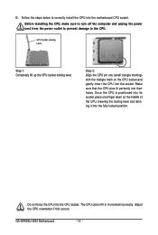
... the middle of the CPU, lowering the locking lever and latching it into the motherboard CPU socket. Do not force the CPU into their holes. GA-M750SLI-DS4 Motherboard - 14 - CPU Socket Locking Lever Step 1: Completely lift up the CPU socket locking lever.
... the middle of the CPU, lowering the locking lever and latching it into the motherboard CPU socket. Do not force the CPU into their holes. GA-M750SLI-DS4 Motherboard - 14 - CPU Socket Locking Lever Step 1: Completely lift up the CPU socket locking lever.
Manual
Page 16
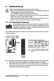
.... When enabling Dual Channel mode with two or four memory modules, it is installed, the BIOS will double the original memory bandwidth. GA-M750SLI-DS4 Motherboard - 16 - If you install them in only one DDR2 memory module is recommended that the motherboard supports the memory. DS/SS...memory module can be installed, it is recommended that memory of the same capacity, brand, speed, and chips be used . (Go to GIGABYTE's website for optimum performance. After the memory is recommended that you are divided into two channels and each channel has two memory sockets as following...
.... When enabling Dual Channel mode with two or four memory modules, it is installed, the BIOS will double the original memory bandwidth. GA-M750SLI-DS4 Motherboard - 16 - If you install them in only one DDR2 memory module is recommended that the motherboard supports the memory. DS/SS...memory module can be installed, it is recommended that memory of the same capacity, brand, speed, and chips be used . (Go to GIGABYTE's website for optimum performance. After the memory is recommended that you are divided into two channels and each channel has two memory sockets as following...
Manual
Page 18
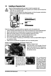
...: Installing and Removing a PCI Express Graphics Card: • Installing a Graphics Card: Gently push down on the card are completely inserted into the PCI Express slot. GA-M750SLI-DS4 Motherboard - 18 - • The motherboard provides a PCIE_12V power connector, which can supply extra power to release the card and then pull the card straight up...
...: Installing and Removing a PCI Express Graphics Card: • Installing a Graphics Card: Gently push down on the card are completely inserted into the PCI Express slot. GA-M750SLI-DS4 Motherboard - 18 - • The motherboard provides a PCIE_12V power connector, which can supply extra power to release the card and then pull the card straight up...
Manual
Page 20
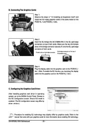
GA-M750SLI-DS4 Motherboard - 20 - B. Female slots on the bridge connector Gold edge connector on the top of the graphics card Step 4: Plug the display cable into the ...
GA-M750SLI-DS4 Motherboard - 20 - B. Female slots on the bridge connector Gold edge connector on the top of the graphics card Step 4: Plug the display cable into the ...
Manual
Page 22
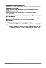
..., walkman, etc. Side Speaker Out Jack (Gray) Use this audio jack to the instructions on setting up a 2/4/5.1/ 7.1-channel audio configuration in Chapter 5, "Configuring 2/4/5.1/7.1-Channel Audio." GA-M750SLI-DS4 Motherboard - 22 - Line In Jack (Blue) The default line in a 5.1/7.1-channel audio configuration. Center/Subwoofer Speaker Out Jack (Orange) Use this audio jack to connect...
..., walkman, etc. Side Speaker Out Jack (Gray) Use this audio jack to the instructions on setting up a 2/4/5.1/ 7.1-channel audio configuration in Chapter 5, "Configuring 2/4/5.1/7.1-Channel Audio." GA-M750SLI-DS4 Motherboard - 22 - Line In Jack (Blue) The default line in a 5.1/7.1-channel audio configuration. Center/Subwoofer Speaker Out Jack (Orange) Use this audio jack to connect...
Manual
Page 24
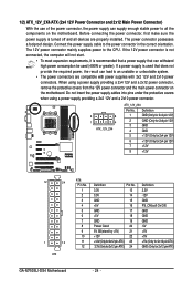
... 3.3V -12V GND PS_ON(soft On/Off) GND GND GND -5V +5V +5V +5V (Only for 2x12 pin ATX) GND (Only for 2x12 pin ATX) GA-M750SLI-DS4 Motherboard - 24 - 1/2) ATX_12V_2X4/ATX (2x4 12V Power Connector and 2x12 Main Power Connector) With the use of the power connector, the power supply can lead...
... 3.3V -12V GND PS_ON(soft On/Off) GND GND GND -5V +5V +5V +5V (Only for 2x12 pin ATX) GND (Only for 2x12 pin ATX) GA-M750SLI-DS4 Motherboard - 24 - 1/2) ATX_12V_2X4/ATX (2x4 12V Power Connector and 2x12 Main Power Connector) With the use of the power connector, the power supply can lead...
Manual
Page 26
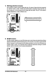
... (for example, master or slave). (For information about configuring master/slave settings for the IDE devices, read the instructions from the device manufacturers.) 40 39 GA-M750SLI-DS4 Motherboard 2 1 - 26 - Before connecting a floppy disk drive, be sure to locate pin 1 of floppy disk drives supported are: 360 KB, 720 KB, 1.2 MB, 1.44 MB...
... (for example, master or slave). (For information about configuring master/slave settings for the IDE devices, read the instructions from the device manufacturers.) 40 39 GA-M750SLI-DS4 Motherboard 2 1 - 26 - Before connecting a floppy disk drive, be sure to locate pin 1 of floppy disk drives supported are: 360 KB, 720 KB, 1.2 MB, 1.44 MB...
Manual
Page 28
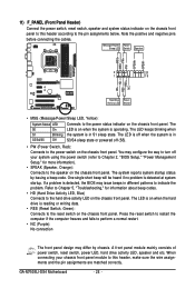
...; RES (Reset Switch, Green): Connects to the power status indicator on the chassis front panel. Note the positive and negative pins before connecting the cables. GA-M750SLI-DS4 Motherboard - 28 - Refer to Chapter 5, "Troubleshooting," for more information). • SPEAK (Speaker, Orange): Connects to the hard drive activity LED on the chassis front panel...
...; RES (Reset Switch, Green): Connects to the power status indicator on the chassis front panel. Note the positive and negative pins before connecting the cables. GA-M750SLI-DS4 Motherboard - 28 - Refer to Chapter 5, "Troubleshooting," for more information). • SPEAK (Speaker, Orange): Connects to the hard drive activity LED on the chassis front panel...
Manual
Page 30
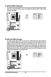
... output from your motherboard to the graphics card and have digital audio output from your motherboard to your expansion card. Pin No. Definition 1 1 SPDIFO 2 GND GA-M750SLI-DS4 Motherboard - 30 - Definition 1 Power 2 SPDIFI 3 GND 15) SPDIF_OUT (S/PDIF Out Header) This header supports digital S/PDIF out and connects a S/PDIF digital audio cable (provided by...
... output from your motherboard to the graphics card and have digital audio output from your motherboard to your expansion card. Pin No. Definition 1 1 SPDIFO 2 GND GA-M750SLI-DS4 Motherboard - 30 - Definition 1 Power 2 SPDIFI 3 GND 15) SPDIF_OUT (S/PDIF Out Header) This header supports digital S/PDIF out and connects a S/PDIF digital audio cable (provided by...
Manual
Page 32
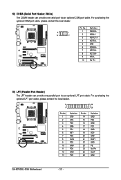
... 16 17 18 19 20 21 22 23 24 25 26 Definition GND PD6 GND PD7 GND ACKGND BUSY GND PE No Pin SLCT GND GA-M750SLI-DS4 Motherboard - 32 - Pin No.
... 16 17 18 19 20 21 22 23 24 25 26 Definition GND PD6 GND PD7 GND ACKGND BUSY GND PE No Pin SLCT GND GA-M750SLI-DS4 Motherboard - 32 - Pin No.

Manual
Page 34
... battery holder and wait for 5 seconds.) 3. Replace the battery. 4. Danger of explosion if the battery is turned off your computer and unplug the power cord. 2. GA-M750SLI-DS4 Motherboard - 34 - You may be handled in accordance with local environmental regulations. Turn off your computer and unplug the power cord before replacing the battery...
... battery holder and wait for 5 seconds.) 3. Replace the battery. 4. Danger of explosion if the battery is turned off your computer and unplug the power cord. 2. GA-M750SLI-DS4 Motherboard - 34 - You may be handled in accordance with local environmental regulations. Turn off your computer and unplug the power cord before replacing the battery...

Manual
Page 36
M750SLI-DS4 D28 . . . . : BIOS Setup : XpressRecovery2 : Boot Menu : Qflash 04/30/2008-NF-MCP78-6A61OG04C-00 Function Keys Function Keys: : POST Screen Press the key to show the BIOS POST screen at system startup, refer to the instructions on the Full Screen LOGO Show item on BIOS Setup settings. GA-M750SLI-D4 Motherboard - 36 - In...
M750SLI-DS4 D28 . . . . : BIOS Setup : XpressRecovery2 : Boot Menu : Qflash 04/30/2008-NF-MCP78-6A61OG04C-00 Function Keys Function Keys: : POST Screen Press the key to show the BIOS POST screen at system startup, refer to the instructions on the Full Screen LOGO Show item on BIOS Setup settings. GA-M750SLI-D4 Motherboard - 36 - In...
Manual
Page 60
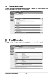
You may press the Install button following an item to install it. 3-3 Driver CD Information This page provides information about the drivers, applications and tools in this driver disk. 3-2 Software Applications This page displays all the tools and applications that GIGABYTE develops and some free software. GA-M750SLI-DS4 Motherboard - 60 -
You may press the Install button following an item to install it. 3-3 Driver CD Information This page provides information about the drivers, applications and tools in this driver disk. 3-2 Software Applications This page displays all the tools and applications that GIGABYTE develops and some free software. GA-M750SLI-DS4 Motherboard - 60 -

Manual
Page 62
GA-M750SLI-DS4 Motherboard - 62 -
GA-M750SLI-DS4 Motherboard - 62 -
Manual
Page 64
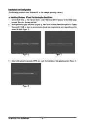
Figure 1 Figure 2 3. Figure 3 GA-M750SLI-DS4 Motherboard - 64 - When partitioning your hard drive (Figure 1), make sure to leave unallocated space for example, NTFS) and begin the installation of data) (Figure 2). Set ...
Figure 1 Figure 2 3. Figure 3 GA-M750SLI-DS4 Motherboard - 64 - When partitioning your hard drive (Figure 1), make sure to leave unallocated space for example, NTFS) and begin the installation of data) (Figure 2). Set ...

