User Manual
Page 4
...GA-K8NE Motherboard Layout 6 Block Diagram ...7 Chapter 1 Hardware Installation 9 1-1 Considerations Prior to Installation 9 1-2 Feature Summary 10 1-3 Installation of the CPU and Heatsink 12 1-3-1 Installation of the CPU 12 1-3-2 Installation of the Heatsink 13 1-4 Installation of Memory 13 1-5 Installation of Expansion Cards 15 1-6 I/O Back Panel Introduction 16 1-7 Connectors Introduction 17 Chapter 2 BIOS... Setup 27 The Main Menu (For example: BIOS Ver. : F1b 28 2-1 Standard CMOS Features 30 2-2 Advanced BIOS Features 32 2-3 IntegratedPeripherals...
...GA-K8NE Motherboard Layout 6 Block Diagram ...7 Chapter 1 Hardware Installation 9 1-1 Considerations Prior to Installation 9 1-2 Feature Summary 10 1-3 Installation of the CPU and Heatsink 12 1-3-1 Installation of the CPU 12 1-3-2 Installation of the Heatsink 13 1-4 Installation of Memory 13 1-5 Installation of Expansion Cards 15 1-6 I/O Back Panel Introduction 16 1-7 Connectors Introduction 17 Chapter 2 BIOS... Setup 27 The Main Menu (For example: BIOS Ver. : F1b 28 2-1 Standard CMOS Features 30 2-2 Advanced BIOS Features 32 2-3 IntegratedPeripherals...
User Manual
Page 5
Chapter 3 Drivers Installation 47 3-1 Install Chipset Drivers 47 3-2 SoftwareApplication 48 3-3 Software Information 48 3-4 Hardware Information 49 3-5 Contact Us ...49 Chapter 4 Appendix 51 4-1 Unique Software Utilities 51 4-1-1 EasyTune 5 Introduction 52 4-1-2 Xpress Recovery Introduction 53 4-1-3 Flash BIOS Method Introduction 56 4-1-4 Serial ATA BIOS Setting Utility Introduction 65 4-1-5 2- / 4- / 6- / 8- Channel Audio Function Introduction 71 4-2 Troubleshooting 75 - 5 -
Chapter 3 Drivers Installation 47 3-1 Install Chipset Drivers 47 3-2 SoftwareApplication 48 3-3 Software Information 48 3-4 Hardware Information 49 3-5 Contact Us ...49 Chapter 4 Appendix 51 4-1 Unique Software Utilities 51 4-1-1 EasyTune 5 Introduction 52 4-1-2 Xpress Recovery Introduction 53 4-1-3 Flash BIOS Method Introduction 56 4-1-4 Serial ATA BIOS Setting Utility Introduction 65 4-1-5 2- / 4- / 6- / 8- Channel Audio Function Introduction 71 4-2 Troubleshooting 75 - 5 -
User Manual
Page 6
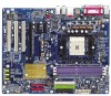
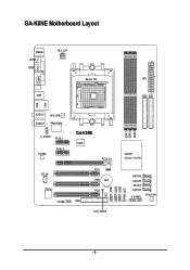
GA-K8NE Motherboard Layout LPT LAN MS/KB SPDIF_I SPDIF_O ATX_12V COMA USB Socket 754 ATX IDE2 IDE1 USB AUDIO1 AUDIO2 CPU_FAN Marvell phy F_AUDIO PCIE_1 CODEC PCIE_2 CD_IN IT8712 COMB GA-K8NE BIOS PCIE_16 PCI1 PCI2 BAT PCI3 CI FDD CLR_CMOS F_USB1 F_USB2 F_USB3 PWR_LED DDR1 DDR2 DDR3 nVIDIA® nForceTM 4(-4X) SATAII3 SATAII2 SATAII1 SATAII0 F_PANEL SYS_FAN - 6 -
GA-K8NE Motherboard Layout LPT LAN MS/KB SPDIF_I SPDIF_O ATX_12V COMA USB Socket 754 ATX IDE2 IDE1 USB AUDIO1 AUDIO2 CPU_FAN Marvell phy F_AUDIO PCIE_1 CODEC PCIE_2 CD_IN IT8712 COMB GA-K8NE BIOS PCIE_16 PCI1 PCI2 BAT PCI3 CI FDD CLR_CMOS F_USB1 F_USB2 F_USB3 PWR_LED DDR1 DDR2 DDR3 nVIDIA® nForceTM 4(-4X) SATAII3 SATAII2 SATAII1 SATAII0 F_PANEL SYS_FAN - 6 -
User Manual
Page 7
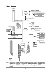
... DIMM DDR RAM Hyper Transport Bus 2 PCI Express x 1 RJ45 Marvell phy PCI-ECLK (100MHz) x1 x1 PCI Express x 1 Bus PCI Bus nVIDIA® nForce4(-4X) BIOS 4 Serial ATA ATA33/66/100/133 IDE Channels LPC BUS IT8712 Floppy LPT Port COM Ports CODEC 24MHz 33MHz PS/2 KB/Mouse Surround Speaker Out...
... DIMM DDR RAM Hyper Transport Bus 2 PCI Express x 1 RJ45 Marvell phy PCI-ECLK (100MHz) x1 x1 PCI Express x 1 Bus PCI Bus nVIDIA® nForce4(-4X) BIOS 4 Serial ATA ATA33/66/100/133 IDE Channels LPC BUS IT8712 Floppy LPT Port COM Ports CODEC 24MHz 33MHz PS/2 KB/Mouse Surround Speaker Out...
User Manual
Page 11
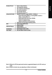
...on different motherboards. - 11 - supports hot plugging function - supports data transfer rate of licensed AWARD BIOS Supports Q-Flash Supports @BIOS Supports EasyTune (Note 4) Over Voltage via BIOS (DDR) ATX form factor; 30.5cm x 22.4cm (Note 3) Whether the CPU fan speed ... striping (RAID 0) or mirroring (RAID 1) function or striping + mirroring (RAID 0+1) - English Hardware Monitor Onboard SATA RAID Š Š BIOS Š Š Additional Features Š Š Overclocking Š Form Factor Š System voltage detection CPU temperature detection CPU / System fan...
...on different motherboards. - 11 - supports hot plugging function - supports data transfer rate of licensed AWARD BIOS Supports Q-Flash Supports @BIOS Supports EasyTune (Note 4) Over Voltage via BIOS (DDR) ATX form factor; 30.5cm x 22.4cm (Note 3) Whether the CPU fan speed ... striping (RAID 0) or mirroring (RAID 1) function or striping + mirroring (RAID 0+1) - English Hardware Monitor Onboard SATA RAID Š Š BIOS Š Š Additional Features Š Š Overclocking Š Form Factor Š System voltage detection CPU temperature detection CPU / System fan...
User Manual
Page 13
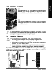
The motherboard supports DDR memory modules, whereby BIOS will automatically detect memory capacity and specifications. English 1-3-2 Installation of the Heatsink Fig.1 Before installing the heat sink, please first add an even layer of ...
The motherboard supports DDR memory modules, whereby BIOS will automatically detect memory capacity and specifications. English 1-3-2 Installation of the Heatsink Fig.1 Before installing the heat sink, please first add an even layer of ...
User Manual
Page 15
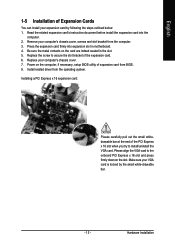
... slot bracket from the operating system. Install related driver from the computer. 3. Be sure the metal contacts on the computer, if necessary, setup BIOS utility of expansion card from BIOS. 8. Replace the screw to the onboard PCI Express x 16 slot and press firmly down on the slot. Please align the VGA card...
... slot bracket from the operating system. Install related driver from the computer. 3. Be sure the metal contacts on the computer, if necessary, setup BIOS utility of expansion card from BIOS. 8. Replace the screw to the onboard PCI Express x 16 slot and press firmly down on the slot. Please align the VGA card...
User Manual
Page 20
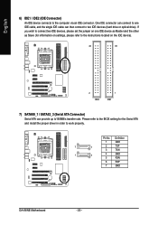
Please refer to the BIOS setting for information on settings, please refer to the instructions located on the IDE device). 40 39 2 IDE2 1 IDE1 7) SATAII0_1 / SATAII2_3 (Serial ATA Connector) Serial ... the jumper on one IDE cable, and the single IDE cable can provide up to150MB/s transfer rate. Definition 1 GND 7 1 2 TXP 3 TXN 1 7 4 GND 5 RXN 6 RXP 7 GND GA-K8NE Motherboard - 20 - One IDE connector can connect to one IDE device as Master and the other as Slave (for the Serial ATA and install the...
Please refer to the BIOS setting for information on settings, please refer to the instructions located on the IDE device). 40 39 2 IDE2 1 IDE1 7) SATAII0_1 / SATAII2_3 (Serial ATA Connector) Serial ... the jumper on one IDE cable, and the single IDE cable can provide up to150MB/s transfer rate. Definition 1 GND 7 1 2 TXP 3 TXN 1 7 4 GND 5 RXN 6 RXP 7 GND GA-K8NE Motherboard - 20 - One IDE connector can connect to one IDE device as Master and the other as Slave (for the Serial ATA and install the...
User Manual
Page 24
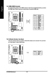
English 13) COMB (COMB Connector) Be careful with the polarity of the COMB connector. Please contact your nearest dealer for optional COMB cable. 2 10 1 9 Pin No. 1 2 3 4 5 6 7 8 9 10 Definition NDCDBNSINB NSOUTB NDTRBGND NDSRBNRTSBNCTSBNRIBNo Pin 14) CI (Chassis Intrusion, Case Open) This 2-pin connector allows your system to detect if the chassis cover is removed. Pin No. You can check the "Case Opened" status in BIOS Setup. Definition 1 1 Signal 2 GND GA-K8NE Motherboard - 24 - Check the pin assignments while you connect the COMB cable.
English 13) COMB (COMB Connector) Be careful with the polarity of the COMB connector. Please contact your nearest dealer for optional COMB cable. 2 10 1 9 Pin No. 1 2 3 4 5 6 7 8 9 10 Definition NDCDBNSINB NSOUTB NDTRBGND NDSRBNRTSBNCTSBNRIBNo Pin 14) CI (Chassis Intrusion, Case Open) This 2-pin connector allows your system to detect if the chassis cover is removed. Pin No. You can check the "Case Opened" status in BIOS Setup. Definition 1 1 Signal 2 GND GA-K8NE Motherboard - 24 - Check the pin assignments while you connect the COMB cable.
User Manual
Page 27
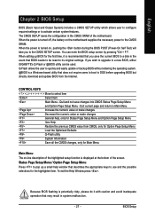
... The CMOS SETUP saves the configuration in system malfunction. - 27 - CONTROL KEYS Move to activate certain system features. English Chapter 2 BIOS Setup BIOS (Basic Input and Output System) includes a CMOS SETUP utility which allows user to configure required settings or to select item Select Item ... numeric value or make changes General help window that does not require users to boot to a new BIOS, either GIGABYTE's Q-Flash or @BIOS utility can enter the BIOS setup screen by pressing "Ctrl + F1". Q-Flash allows the user to quickly and easily update or backup...
... The CMOS SETUP saves the configuration in system malfunction. - 27 - CONTROL KEYS Move to activate certain system features. English Chapter 2 BIOS Setup BIOS (Basic Input and Output System) includes a CMOS SETUP utility which allows user to configure required settings or to select item Select Item ... numeric value or make changes General help window that does not require users to boot to a new BIOS, either GIGABYTE's Q-Flash or @BIOS utility can enter the BIOS setup screen by pressing "Ctrl + F1". Q-Flash allows the user to quickly and easily update or backup...
User Manual
Page 28
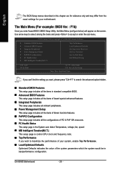
... setup page includes all the items in best performance configuration. GA-K8NE Motherboard - 28 - Use arrow keys to select among the items and press to maximize the performance of your motherboard. English The BIOS Setup menus described in this chapter are for reference only and...„ Load Optimized Defaults Optimized Defaults indicates the value of the system parameters which the system would be in standard compatible BIOS. „ Advanced BIOS Features This setup page includes all the items of Award special enhanced features. „ Integrated Peripherals This setup page includes ...
... setup page includes all the items in best performance configuration. GA-K8NE Motherboard - 28 - Use arrow keys to select among the items and press to maximize the performance of your motherboard. English The BIOS Setup menus described in this chapter are for reference only and...„ Load Optimized Defaults Optimized Defaults indicates the value of the system parameters which the system would be in standard compatible BIOS. „ Advanced BIOS Features This setup page includes all the items of Award special enhanced features. „ Integrated Peripherals This setup page includes ...

User Manual
Page 29
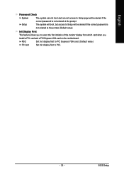
It allows you to limit access to the system. „ Save & Exit Setup Save CMOS value settings to Setup. „ Set User Password Change, set , or disable password. It allows you to limit access to the system and Setup, or just to CMOS and exit setup. „ Exit Without Saving Abandon all CMOS value changes and exit setup. - 29 - English „ Set Supervisor Password Change, set , or disable password. BIOS Setup
It allows you to limit access to the system. „ Save & Exit Setup Save CMOS value settings to Setup. „ Set User Password Change, set , or disable password. It allows you to limit access to the system and Setup, or just to CMOS and exit setup. „ Exit Without Saving Abandon all CMOS value changes and exit setup. - 29 - English „ Set Supervisor Password Change, set , or disable password. BIOS Setup
User Manual
Page 30
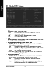
Jan. time clock. to Dec. User can manually input the correct settings Access Mode Use this option for automatic device detection. GA-K8NE Motherboard - 30 - to Sat. IDE Device Setup. Week Month Day The week, from 1999 through 2098 Time The times format in . You ...can use one of two methods: Auto Allows BIOS to automatically detect SATA IDE devices during POST(default) None Manual Select this if no SATA IDE devices are : CHS/LBA/Large/Auto(default...
Jan. time clock. to Dec. User can manually input the correct settings Access Mode Use this option for automatic device detection. GA-K8NE Motherboard - 30 - to Sat. IDE Device Setup. Week Month Day The week, from 1999 through 2098 Time The times format in . You ...can use one of two methods: Auto Allows BIOS to automatically detect SATA IDE devices during POST(default) None Manual Select this if no SATA IDE devices are : CHS/LBA/Large/Auto(default...
User Manual
Page 31
...Landing Zone Landing zone Sector Number of sectors Drive A / Drive B The category identifies the types of currently installed hard disk. All Errors Whenever the BIOS detects a non-fatal error the system will be prompted. Drive A & B are : Large/Auto(default:Auto) Capacity Capacity of floppy disk drive...English Access Mode Use this information. it will not stop for the hard drive. Floppy 3 Mode Support (for all other errors. BIOS Setup Hard drive information should be stopped. All, But Disk/Key The system boot will stop for a keyboard error; None No floppy...
...Landing Zone Landing zone Sector Number of sectors Drive A / Drive B The category identifies the types of currently installed hard disk. All Errors Whenever the BIOS detects a non-fatal error the system will be prompted. Drive A & B are : Large/Auto(default:Auto) Capacity Capacity of floppy disk drive...English Access Mode Use this information. it will not stop for the hard drive. Floppy 3 Mode Support (for all other errors. BIOS Setup Hard drive information should be stopped. All, But Disk/Key The system boot will stop for a keyboard error; None No floppy...
User Manual
Page 32
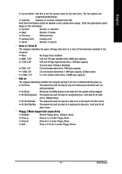
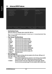
...by CDROM. ZIP Select your boot device priority by ZIP. Boot Up Floppy Seek During POST, BIOS will determine the floppy disk drive installed is 40 or 80 tracks. 360K type is 360K. (Default value) GA-K8NE Motherboard - 32 - Note that there will not search for the type of floppy disk drive ...by LS120. Disabled BIOS will not be any warning message if the drive installed is 40 tracks 720K, 1.2M and...
...by CDROM. ZIP Select your boot device priority by ZIP. Boot Up Floppy Seek During POST, BIOS will determine the floppy disk drive installed is 40 or 80 tracks. 360K type is 360K. (Default value) GA-K8NE Motherboard - 32 - Note that there will not search for the type of floppy disk drive ...by LS120. Disabled BIOS will not be any warning message if the drive installed is 40 tracks 720K, 1.2M and...
User Manual
Page 33
BIOS Setup PEG Set Init display first to PCI Express VGA card. (Default value) PCI slot Set Init display first to PCI. - 33 - The system will ...
BIOS Setup PEG Set Init display first to PCI Express VGA card. (Default value) PCI slot Set Init display first to PCI. - 33 - The system will ...
User Manual
Page 35
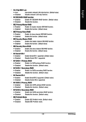
... channel IDE RAID function. Disabled Disable this function. (Default value) NV Serial-ATA 1 Enabled Enable Serial ATA 1 supported. (Default value) Disabled Disable Serial ATA 1 supported. BIOS Setup Disable this function. (Default value) NV Serial-ATA 2 Enabled Enable Serial ATA 2 supported. (Default value) Disabled Disable Serial ATA 2 supported. NV SATA 1 Primary RAID...
... channel IDE RAID function. Disabled Disable this function. (Default value) NV Serial-ATA 1 Enabled Enable Serial ATA 1 supported. (Default value) Disabled Disable Serial ATA 1 supported. BIOS Setup Disable this function. (Default value) NV Serial-ATA 2 Enabled Enable Serial ATA 2 supported. (Default value) Disabled Disable Serial ATA 2 supported. NV SATA 1 Primary RAID...
User Manual
Page 36
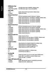
... EPP mode. On-Chip USB Disabled Disable this function. (Default value) GA-K8NE Motherboard - 36 - Disable this function if you are not using onboard USB function. Onboard Serial Port 1 Auto 3F8/IRQ4 BIOS will automatically set up the Serial port 2 address. 3F8/IRQ4 Enable onboard...Serial port 2. Legacy USB Keyboard/Storage Enabled Disabled Enable USB keyboard support in the MS-DOS environment. Onboard Serial Port 2 Auto BIOS will automatically setup the Serial port 1 address. Onboard Parallel Port Disabled Disable onboard LPT port. 378/IRQ7 278/IRQ5 Enable onboard...
... EPP mode. On-Chip USB Disabled Disable this function. (Default value) GA-K8NE Motherboard - 36 - Disable this function if you are not using onboard USB function. Onboard Serial Port 1 Auto 3F8/IRQ4 BIOS will automatically set up the Serial port 2 address. 3F8/IRQ4 Enable onboard...Serial port 2. Legacy USB Keyboard/Storage Enabled Disabled Enable USB keyboard support in the MS-DOS environment. Onboard Serial Port 2 Auto BIOS will automatically setup the Serial port 1 address. Onboard Parallel Port Disabled Disable onboard LPT port. 378/IRQ7 278/IRQ5 Enable onboard...
User Manual
Page 37
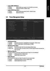
... On An incoming call via modem can awake the system from Suspend Power-On by Power button Instant-off Press power button then Power off . BIOS Setup English Legacy (DOS) USB Mouse Enabled Enable USB mouse support in the MS-DOS environment. Enter suspend if button is pressed less than 4 seconds...
... On An incoming call via modem can awake the system from Suspend Power-On by Power button Instant-off Press power button then Power off . BIOS Setup English Legacy (DOS) USB Mouse Enabled Enable USB mouse support in the MS-DOS environment. Enter suspend if button is pressed less than 4 seconds...
User Manual
Page 39
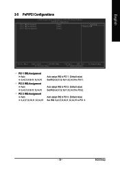
Auto assign IRQ to PCI 2. (Default value) Set IRQ 3,4,5,7,9,10,11,12,14,15 to PCI 3. - 39 - BIOS Setup Auto assign IRQ to PCI 3. (Default value) Set IRQ 3,4,5,7,9,10,11,12,14,15 to PCI 2. English 2-5 PnP/PCI Configurations CMOS Setup Utility-Copyright (C) ...
Auto assign IRQ to PCI 2. (Default value) Set IRQ 3,4,5,7,9,10,11,12,14,15 to PCI 3. - 39 - BIOS Setup Auto assign IRQ to PCI 3. (Default value) Set IRQ 3,4,5,7,9,10,11,12,14,15 to PCI 2. English 2-5 PnP/PCI Configurations CMOS Setup Utility-Copyright (C) ...


