User Manual
Page 1
GA-K8NE AMD Socket 754 Processor Motherboard User's Manual Rev. 2004 12ME-K8NE-2004R * The WEEE marking on the product indicates this product must not be disposed of with user's other household waste and must be handed over to a designated collection point for the recycling of waste electrical and electronic equipment!! * The WEEE marking applies only in European Union's member states.
GA-K8NE AMD Socket 754 Processor Motherboard User's Manual Rev. 2004 12ME-K8NE-2004R * The WEEE marking on the product indicates this product must not be disposed of with user's other household waste and must be handed over to a designated collection point for the recycling of waste electrical and electronic equipment!! * The WEEE marking applies only in European Union's member states.
User Manual
Page 2
Motherboard GA-K8NE Sep. 20, 2005 Motherboard GA-K8NE Sep. 20, 2005
Motherboard GA-K8NE Sep. 20, 2005 Motherboard GA-K8NE Sep. 20, 2005
User Manual
Page 4
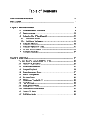
Table of Contents GA-K8NE Motherboard Layout 6 Block Diagram ...7 Chapter 1 Hardware Installation 9 1-1 Considerations Prior to Installation 9 1-2 Feature Summary 10 1-3 Installation of the CPU and Heatsink 12 1-3-1 Installation of the CPU 12 1-3-2 ...
Table of Contents GA-K8NE Motherboard Layout 6 Block Diagram ...7 Chapter 1 Hardware Installation 9 1-1 Considerations Prior to Installation 9 1-2 Feature Summary 10 1-3 Installation of the CPU and Heatsink 12 1-3-1 Installation of the CPU 12 1-3-2 ...
User Manual
Page 6
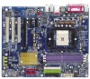
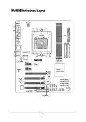
GA-K8NE Motherboard Layout LPT LAN MS/KB SPDIF_I SPDIF_O ATX_12V COMA USB Socket 754 ATX IDE2 IDE1 USB AUDIO1 AUDIO2 CPU_FAN Marvell phy F_AUDIO PCIE_1 CODEC PCIE_2 CD_IN IT8712 COMB GA-K8NE BIOS PCIE_16 PCI1 PCI2 BAT PCI3 CI FDD CLR_CMOS F_USB1 F_USB2 F_USB3 PWR_LED DDR1 DDR2 DDR3 nVIDIA® nForceTM 4(-4X) SATAII3 SATAII2 SATAII1 SATAII0 F_PANEL SYS_FAN - 6 -
GA-K8NE Motherboard Layout LPT LAN MS/KB SPDIF_I SPDIF_O ATX_12V COMA USB Socket 754 ATX IDE2 IDE1 USB AUDIO1 AUDIO2 CPU_FAN Marvell phy F_AUDIO PCIE_1 CODEC PCIE_2 CD_IN IT8712 COMB GA-K8NE BIOS PCIE_16 PCI1 PCI2 BAT PCI3 CI FDD CLR_CMOS F_USB1 F_USB2 F_USB3 PWR_LED DDR1 DDR2 DDR3 nVIDIA® nForceTM 4(-4X) SATAII3 SATAII2 SATAII1 SATAII0 F_PANEL SYS_FAN - 6 -
User Manual
Page 9
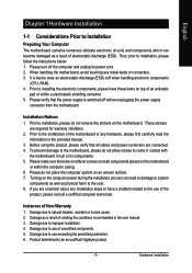
... system on top of an antistatic pad or within the computer casing. 6. Damage due to be an unofficial Gigabyte product. - 9 - Damage due to use exceeding the permitted parameters. 6. Hardware Installation When handling the motherboard, avoid touching any installation steps or have these items on an uneven surface. 7. Before using the product, please...
... system on top of an antistatic pad or within the computer casing. 6. Damage due to be an unofficial Gigabyte product. - 9 - Damage due to use exceeding the permitted parameters. 6. Hardware Installation When handling the motherboard, avoid touching any installation steps or have these items on an uneven surface. 7. Before using the product, please...
User Manual
Page 10
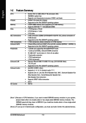
...; Supports core frequencies in your system, please install either one double-sided or two single-sided DDR400 memory modules. Surround Speaker Out (Rear Speaker Out) ; GA-K8NE Motherboard - 10 - The DDR400 speed will drop down to install DDR400 memory modules in excess of 3000+ and faster Š nVIDIA® nForce4(-4X) Chipset Š...
...; Supports core frequencies in your system, please install either one double-sided or two single-sided DDR400 memory modules. Surround Speaker Out (Rear Speaker Out) ; GA-K8NE Motherboard - 10 - The DDR400 speed will drop down to install DDR400 memory modules in excess of 3000+ and faster Š nVIDIA® nForce4(-4X) Chipset Š...
User Manual
Page 11
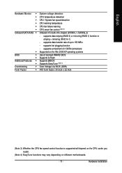
... 3) Whether the CPU fan speed control function is supported will depend on the CPU cooler you install. (Note 4) EasyTune functions may vary depending on different motherboards. - 11 - Hardware Installation supports hot plugging function - supports data striping (RAID 0) or mirroring (RAID 1) function or striping + mirroring (RAID 0+1) - English Hardware Monitor Onboard SATA RAID...
... 3) Whether the CPU fan speed control function is supported will depend on the CPU cooler you install. (Note 4) EasyTune functions may vary depending on different motherboards. - 11 - Hardware Installation supports hot plugging function - supports data striping (RAID 0) or mirroring (RAID 1) function or striping + mirroring (RAID 0+1) - English Hardware Monitor Onboard SATA RAID...
User Manual
Page 12
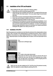
...If this occurs, please change the positioning of the CPU. 3. Please set beyond hardware specifications since it into position making sure that the motherboard supports the CPU. 2. Gently place the CPU into place. Rather than applying force, please change the insert direction of the CPU. Please ... CPU pins fit perfectly into its socket, place one indented corner of the CPU. Do not force the processor into its original position. GA-K8NE Motherboard - 12 - It is designated on the processor by a copper triangle that matches up to the socket and gently lower it does not...
...If this occurs, please change the positioning of the CPU. 3. Please set beyond hardware specifications since it into position making sure that the motherboard supports the CPU. 2. Gently place the CPU into place. Rather than applying force, please change the insert direction of the CPU. Please ... CPU pins fit perfectly into its socket, place one indented corner of the CPU. Do not force the processor into its original position. GA-K8NE Motherboard - 12 - It is designated on the processor by a copper triangle that matches up to the socket and gently lower it does not...
User Manual
Page 13
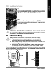
... of Memory Before installing the memory modules, please comply with each slot. It is recommended that the computer power is supported by the motherboard. Notch DDR - 13 - Before installing or removing memory modules, please make sure that the memory used . 2. The memory capacity ... of similar capacity, specifications and brand be inserted only in only one direction. Memory modules have a foolproof insertion design. The motherboard supports DDR memory modules, whereby BIOS will automatically detect memory capacity and specifications. The heat sink may adhere to the CPU as...
... of Memory Before installing the memory modules, please comply with each slot. It is recommended that the computer power is supported by the motherboard. Notch DDR - 13 - Before installing or removing memory modules, please make sure that the memory used . 2. The memory capacity ... of similar capacity, specifications and brand be inserted only in only one direction. Memory modules have a foolproof insertion design. The motherboard supports DDR memory modules, whereby BIOS will automatically detect memory capacity and specifications. The heat sink may adhere to the CPU as...
User Manual
Page 14
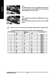
... 400 DDR 400 DDR 400 DDR 400 DDR 400 DDR 400 DDR 400 DDR 400 DDR 333 DDR 333 DDR 333 DDR 333 DDR 333 GA-K8NE Motherboard - 14 - Insert the DIMM memory module vertically into the DIMM socket. Then push it down. Fig.2 Close the plastic clip at both edges of DIMMs...
... 400 DDR 400 DDR 400 DDR 400 DDR 400 DDR 400 DDR 400 DDR 400 DDR 333 DDR 333 DDR 333 DDR 333 DDR 333 GA-K8NE Motherboard - 14 - Insert the DIMM memory module vertically into the DIMM socket. Then push it down. Fig.2 Close the plastic clip at both edges of DIMMs...
User Manual
Page 15
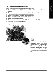
... PCI Express x 16 slot when you try to the onboard PCI Express x 16 slot and press firmly down on the card are indeed seated in motherboard. 4. Be sure the metal contacts on the slot. Please align the VGA card to install/uninstall the VGA card. Replace your computer's chassis cover, screws...
... PCI Express x 16 slot when you try to the onboard PCI Express x 16 slot and press firmly down on the card are indeed seated in motherboard. 4. Be sure the metal contacts on the slot. Please align the VGA card to install/uninstall the VGA card. Replace your computer's chassis cover, screws...
User Manual
Page 16
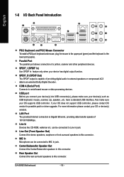
... USB controller, please contact OS vendor for possible patch or driver upgrade. Rear Speaker Out Connect the rear surround speakers to the lower port (purple). GA-K8NE Motherboard - 16 - USB port Before you connect your device(s) into USB connector(s), please make sure your device has digital output function. English 1-6 I/O Back Panel Introduction PS...
... USB controller, please contact OS vendor for possible patch or driver upgrade. Rear Speaker Out Connect the rear surround speakers to the lower port (purple). GA-K8NE Motherboard - 16 - USB port Before you connect your device(s) into USB connector(s), please make sure your device has digital output function. English 1-6 I/O Back Panel Introduction PS...

User Manual
Page 18
.../Off) 17 GND 18 GND 19 GND 20 -5V 21 +5V 22 +5V 23 +5V(Only for 24pins ATX) 24 GND(Only for 24pins ATX) GA-K8NE Motherboard - 18 - If the ATX_12V power connector is used (300W or greater). Pin No. English 1/2) ATX_12V / ATX (Power Connector) With the use of the power... connector, the power supply can lead to an unstable system or a system that all the components on the motherboard. Before connecting the power connector, please make sure that is able to the CPU. If a power supply is not connected, the system will not...
.../Off) 17 GND 18 GND 19 GND 20 -5V 21 +5V 22 +5V 23 +5V(Only for 24pins ATX) 24 GND(Only for 24pins ATX) GA-K8NE Motherboard - 18 - If the ATX_12V power connector is used (300W or greater). Pin No. English 1/2) ATX_12V / ATX (Power Connector) With the use of the power... connector, the power supply can lead to an unstable system or a system that all the components on the motherboard. Before connecting the power connector, please make sure that is able to the CPU. If a power supply is not connected, the system will not...
User Manual
Page 20
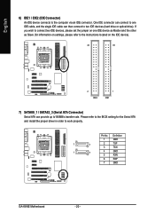
Definition 1 GND 7 1 2 TXP 3 TXN 1 7 4 GND 5 RXN 6 RXP 7 GND GA-K8NE Motherboard - 20 - English 6) IDE1 / IDE2 (IDE Connector) An IDE device connects to work properly. Pin No. If you wish to connect two IDE devices, please set ...
Definition 1 GND 7 1 2 TXP 3 TXN 1 7 4 GND 5 RXN 6 RXP 7 GND GA-K8NE Motherboard - 20 - English 6) IDE1 / IDE2 (IDE Connector) An IDE device connects to work properly. Pin No. If you wish to connect two IDE devices, please set ...
User Manual
Page 22
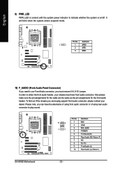
... blink when the system enters suspend mode. Definition 10 9 1 MIC 2 GND 2 1 3 MIC_BIAS 4 POWER 5 FrontAudio(R) 6 Rear Audio (R)/ Return R 7 NC 8 No Pin 9 FrontAudio (L) 10 Rear Audio (L)/ Return L GA-K8NE Motherboard - 22 - English 9) PWR_LED PWR_LED is on/off. To find out if the chassis you can have front audio connector.
... blink when the system enters suspend mode. Definition 10 9 1 MIC 2 GND 2 1 3 MIC_BIAS 4 POWER 5 FrontAudio(R) 6 Rear Audio (R)/ Return R 7 NC 8 No Pin 9 FrontAudio (L) 10 Rear Audio (L)/ Return L GA-K8NE Motherboard - 22 - English 9) PWR_LED PWR_LED is on/off. To find out if the chassis you can have front audio connector.
User Manual
Page 24
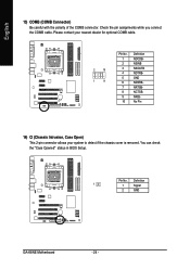
Pin No. Definition 1 1 Signal 2 GND GA-K8NE Motherboard - 24 - You can check the "Case Opened" status in BIOS Setup. Check the pin assignments while you connect the COMB cable. English 13) COMB (COMB Connector) Be careful with the polarity of the COMB connector. Please contact your nearest dealer for optional COMB cable. 2 10 1 9 Pin No. 1 2 3 4 5 6 7 8 9 10 Definition NDCDBNSINB NSOUTB NDTRBGND NDSRBNRTSBNCTSBNRIBNo Pin 14) CI (Chassis Intrusion, Case Open) This 2-pin connector allows your system to detect if the chassis cover is removed.
Pin No. Definition 1 1 Signal 2 GND GA-K8NE Motherboard - 24 - You can check the "Case Opened" status in BIOS Setup. Check the pin assignments while you connect the COMB cable. English 13) COMB (COMB Connector) Be careful with the polarity of the COMB connector. Please contact your nearest dealer for optional COMB cable. 2 10 1 9 Pin No. 1 2 3 4 5 6 7 8 9 10 Definition NDCDBNSINB NSOUTB NDTRBGND NDSRBNRTSBNCTSBNRIBNo Pin 14) CI (Chassis Intrusion, Case Open) This 2-pin connector allows your system to detect if the chassis cover is removed.
User Manual
Page 26
English GA-K8NE Motherboard - 26 -
English GA-K8NE Motherboard - 26 -
User Manual
Page 27
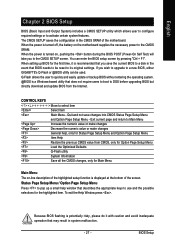
...Menu and Option Page Setup Menu Item Help Restore the previous CMOS value from the Internet. If you wish to upgrade to a new BIOS, either GIGABYTE's Q-Flash or @BIOS utility can enter the BIOS setup screen by pressing "Ctrl + F1". To exit the Help Window press . When the... CONTROL KEYS Move to activate certain system features. Because BIOS flashing is potentially risky, please do it is displayed at the bottom of the motherboard. Q-Flash allows the user to quickly and easily update or backup BIOS without entering the operating system. @BIOS is turned off, the battery ...
...Menu and Option Page Setup Menu Item Help Restore the previous CMOS value from the Internet. If you wish to upgrade to a new BIOS, either GIGABYTE's Q-Flash or @BIOS utility can enter the BIOS setup screen by pressing "Ctrl + F1". To exit the Help Window press . When the... CONTROL KEYS Move to activate certain system features. Because BIOS flashing is potentially risky, please do it is displayed at the bottom of the motherboard. Q-Flash allows the user to quickly and easily update or backup BIOS without entering the operating system. @BIOS is turned off, the battery ...
User Manual
Page 28
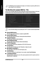
Use arrow keys to select among the items and press to maximize the performance of your motherboard. GA-K8NE Motherboard - 28 - English The BIOS Setup menus described in this chapter are for reference only and may differ from the exact settings for your system, enable ...
Use arrow keys to select among the items and press to maximize the performance of your motherboard. GA-K8NE Motherboard - 28 - English The BIOS Setup menus described in this chapter are for reference only and may differ from the exact settings for your system, enable ...
User Manual
Page 30
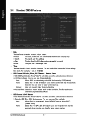
.... For example, 1 p.m. IDE Device Setup. The four options are used and the system will skip the automatic detection step and allow for automatic device detection. GA-K8NE Motherboard - 30 - Week Month Day The week, from 1999 through 2098 Time The times format in the month) Year The year, from Sun to Sat. User...
.... For example, 1 p.m. IDE Device Setup. The four options are used and the system will skip the automatic detection step and allow for automatic device detection. GA-K8NE Motherboard - 30 - Week Month Day The week, from 1999 through 2098 Time The times format in the month) Year The year, from Sun to Sat. User...


