Manual
Page 1
GA-H55M-S2 LGA1156 socket motherboard for Intel® Core™ i7 processors/Intel® Core™ i5 processors/Intel® Core™ i3 processors/Intel® Pentium® processors User's Manual Rev. 1301 12ME-H55MS2-1301R
GA-H55M-S2 LGA1156 socket motherboard for Intel® Core™ i7 processors/Intel® Core™ i5 processors/Intel® Core™ i3 processors/Intel® Pentium® processors User's Manual Rev. 1301 12ME-H55MS2-1301R
Manual
Page 2
Motherboard GA-H55M-S2 Jun. 21, 2010 Motherboard GA-H55M-S2 Jun. 21, 2010
Motherboard GA-H55M-S2 Jun. 21, 2010 Motherboard GA-H55M-S2 Jun. 21, 2010
Manual
Page 3
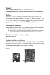
... this manual are legally registered to their respective owners. The trademarks mentioned in the use of GIGABYTE. For product-related information, check on our website at: http://www.gigabyte.com Identifying Your Motherboard Revision The revision number on your motherboard revision before updating motherboard BIOS, drivers, or when looking for technical information. Changes to use...
... this manual are legally registered to their respective owners. The trademarks mentioned in the use of GIGABYTE. For product-related information, check on our website at: http://www.gigabyte.com Identifying Your Motherboard Revision The revision number on your motherboard revision before updating motherboard BIOS, drivers, or when looking for technical information. Changes to use...
Manual
Page 4
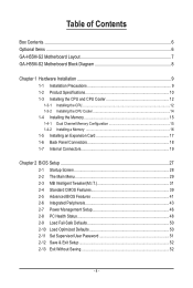
Table of Contents Box Contents...6 Optional Items...6 GA-H55M-S2 Motherboard Layout 7 GA-H55M-S2 Motherboard Block Diagram 8 Chapter 1 Hardware Installation 9 1-1 Installation Precautions 9 1-2 Product Specifications 10 1-3 Installing the CPU and CPU Cooler 12 1-3-1 Installing the CPU 12 1-3-2 Installing the CPU Cooler ...
Table of Contents Box Contents...6 Optional Items...6 GA-H55M-S2 Motherboard Layout 7 GA-H55M-S2 Motherboard Block Diagram 8 Chapter 1 Hardware Installation 9 1-1 Installation Precautions 9 1-2 Product Specifications 10 1-3 Installing the CPU and CPU Cooler 12 1-3-1 Installing the CPU 12 1-3-2 Installing the CPU Cooler ...
Manual
Page 6
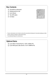
Optional Items 2-port USB 2.0 bracket (Part No. 12CR1-1UB030-5*R) 2-port SATA power cable (Part No. 12CF1-2SERPW-0*R) - 6 - Box Contents GA-H55M-S2 motherboard Motherboard driver disk User's Manual Two SATA cables I/O Shield • The box contents above are subject to change without notice. • The motherboard image is for reference only and the actual items shall depend on the product package you obtain. The box contents are for reference only.
Optional Items 2-port USB 2.0 bracket (Part No. 12CR1-1UB030-5*R) 2-port SATA power cable (Part No. 12CF1-2SERPW-0*R) - 6 - Box Contents GA-H55M-S2 motherboard Motherboard driver disk User's Manual Two SATA cables I/O Shield • The box contents above are subject to change without notice. • The motherboard image is for reference only and the actual items shall depend on the product package you obtain. The box contents are for reference only.
Manual
Page 7
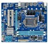
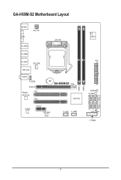
GA-H55M-S2 Motherboard Layout KB_MS VGA ATX_12V R_USB3 LGA1156 R_USB2 R_USB1 CPU_FAN USB_LAN AUDIO F_AUDIO PCIEX16 Realtek PCI1 RTL8111E PCI2 BAT GA-H55M-S2 Intel® H55 CODEC PCIEX1 SYS_FAN F_USB2 F_USB1 iTE IT8720 ATX M_BIOS B_BIOS CLR_CMOS F_PANEL DDR3_1 DDR3_2 SATA2_5 SATA2_2 SATA2_4 SATA2_1 SATA2_3 SATA2_0 - 7 -
GA-H55M-S2 Motherboard Layout KB_MS VGA ATX_12V R_USB3 LGA1156 R_USB2 R_USB1 CPU_FAN USB_LAN AUDIO F_AUDIO PCIEX16 Realtek PCI1 RTL8111E PCI2 BAT GA-H55M-S2 Intel® H55 CODEC PCIEX1 SYS_FAN F_USB2 F_USB1 iTE IT8720 ATX M_BIOS B_BIOS CLR_CMOS F_PANEL DDR3_1 DDR3_2 SATA2_5 SATA2_2 SATA2_4 SATA2_1 SATA2_3 SATA2_0 - 7 -
Manual
Page 8
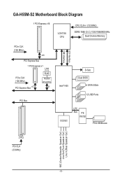
GA-H55M-S2 Motherboard Block Diagram 1 PCI Express x16 LGA1156 CPU CPU CLK+/- (133 MHz) DDR3 1666 (O.C.)/1333/1066/800 MHz Dual Channel Memory PCIe CLK (100 MHz) x16 PCI Express Bus 1 PCI Express x1 LAN PCIe CLK (100 MHz) PCI Express Bus x1 RJ45 Realtek RTL8111E x1 PCI Bus FDI Interface DMI Interface Intel® H55 D-Sub Dual BIOS 6 SATA 3Gb/s 12 USB Ports CODEC LPC Bus iTE IT8720 PS/2 KB/Mouse 2 PCI PCI CLK (33 MHz) MIC (Center/Subwoofer Speakcer Out ) Line Out (Front Speakcer Out ) Line In (Rear Speakcer Out ) - 8 -
GA-H55M-S2 Motherboard Block Diagram 1 PCI Express x16 LGA1156 CPU CPU CLK+/- (133 MHz) DDR3 1666 (O.C.)/1333/1066/800 MHz Dual Channel Memory PCIe CLK (100 MHz) x16 PCI Express Bus 1 PCI Express x1 LAN PCIe CLK (100 MHz) PCI Express Bus x1 RJ45 Realtek RTL8111E x1 PCI Bus FDI Interface DMI Interface Intel® H55 D-Sub Dual BIOS 6 SATA 3Gb/s 12 USB Ports CODEC LPC Bus iTE IT8720 PS/2 KB/Mouse 2 PCI PCI CLK (33 MHz) MIC (Center/Subwoofer Speakcer Out ) Line Out (Front Speakcer Out ) Line In (Rear Speakcer Out ) - 8 -
Manual
Page 9
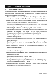
... are required for warranty validation. • Always remove the AC power by your hardware components are connected. • To prevent damage to the motherboard, do not have an ESD wrist strap, keep your hands dry and first touch a metal object to eliminate static electricity. • Prior to... the computer system on an uneven surface. • Do not place the computer system in a high-temperature environment. • Turning on the motherboard, make sure the power supply voltage has been set according to the local voltage standard. • Before using the product, please verify that all...
... are required for warranty validation. • Always remove the AC power by your hardware components are connected. • To prevent damage to the motherboard, do not have an ESD wrist strap, keep your hands dry and first touch a metal object to eliminate static electricity. • Prior to... the computer system on an uneven surface. • Do not place the computer system in a high-temperature environment. • Turning on the motherboard, make sure the power supply voltage has been set according to the local voltage standard. • Before using the product, please verify that all...
Manual
Page 11
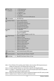
... 4) Whether the CPU fan speed control function is supported will depend on the CPU cooler you install. (Note 5) Available functions in EasyTune may differ by motherboard model. - 11 -
... 4) Whether the CPU fan speed control function is supported will depend on the CPU cooler you install. (Note 5) Available functions in EasyTune may differ by motherboard model. - 11 -
Manual
Page 12
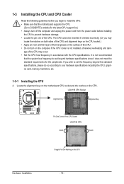
Locate the alignment keys on the motherboard CPU socket and the notches on the CPU Hardware Installation - 12 - The CPU cannot be set the frequency beyond hardware specifications since it does not ... standard requirements for the latest CPU support list.) • Always turn on the computer if the CPU cooler is not recommended that the motherboard supports the CPU. (Go to GIGABYTE's website for the peripherals. It is not installed, otherwise overheating and dam- 1-3 Installing the CPU and CPU Cooler Read the following guidelines...
Locate the alignment keys on the motherboard CPU socket and the notches on the CPU Hardware Installation - 12 - The CPU cannot be set the frequency beyond hardware specifications since it does not ... standard requirements for the latest CPU support list.) • Always turn on the computer if the CPU cooler is not recommended that the motherboard supports the CPU. (Go to GIGABYTE's website for the peripherals. It is not installed, otherwise overheating and dam- 1-3 Installing the CPU and CPU Cooler Read the following guidelines...
Manual
Page 13
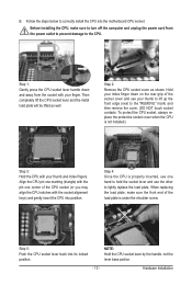
... CPU is under the shoulder screw. B. Hardware Installation Hold your thumb to lift up the front edge (next to correctly install the CPU into the motherboard CPU socket. Follow the steps below to the "REMOVE" mark) and then remove the cover. (DO NOT touch socket contacts.
... CPU is under the shoulder screw. B. Hardware Installation Hold your thumb to lift up the front edge (next to correctly install the CPU into the motherboard CPU socket. Follow the steps below to the "REMOVE" mark) and then remove the cover. (DO NOT touch socket contacts.

Manual
Page 14
...the contrary, is to your CPU cooler installation manual for instructions on installing the cooler.) Step 5: After the installation, check the back of the motherboard. Hardware Installation - 14 - Step 4: You should hear a "click" when pushing down on the push pins diagonally. Check that the Male ...the CPU cooler may adhere to the CPU. 1-3-2 Installing the CPU Cooler Follow the steps below to correctly install the CPU cooler on the motherboard. (The following procedure uses Intel® boxed cooler as the picture above shows, the installation is complete. Push down each push pin....
...the contrary, is to your CPU cooler installation manual for instructions on installing the cooler.) Step 5: After the installation, check the back of the motherboard. Hardware Installation - 14 - Step 4: You should hear a "click" when pushing down on the push pins diagonally. Check that the Male ...the CPU cooler may adhere to the CPU. 1-3-2 Installing the CPU Cooler Follow the steps below to correctly install the CPU cooler on the motherboard. (The following procedure uses Intel® boxed cooler as the picture above shows, the installation is complete. Push down each push pin....
Manual
Page 15
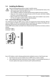
... if only one DDR3 memory module is installed, the BIOS will double the original memory bandwidth. If you begin to GIGABYTE's website for optimum performance. - 15 - Dual Channel Memory Configuration This motherboard provides two DDR3 memory sockets and supports Dual Channel Technology. Enabling Dual Channel memory mode will automatically detect the specifications... prevent hardware damage. • Memory modules have a foolproof design. Hardware Installation When enabling Dual Channel mode with two memory modules, it is recommended that the motherboard supports the memory.
... if only one DDR3 memory module is installed, the BIOS will double the original memory bandwidth. If you begin to GIGABYTE's website for optimum performance. - 15 - Dual Channel Memory Configuration This motherboard provides two DDR3 memory sockets and supports Dual Channel Technology. Enabling Dual Channel memory mode will automatically detect the specifications... prevent hardware damage. • Memory modules have a foolproof design. Hardware Installation When enabling Dual Channel mode with two memory modules, it is recommended that the motherboard supports the memory.
Manual
Page 16
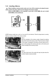
Place the memory module on this motherboard. DDR3 and DDR2 DIMMs are not compatible to each other or DDR DIMMs. Be sure to install DDR3 DIMMs on the socket. Step 1: Note the ...
Place the memory module on this motherboard. DDR3 and DDR2 DIMMs are not compatible to each other or DDR DIMMs. Be sure to install DDR3 DIMMs on the socket. Step 1: Note the ...
Manual
Page 17
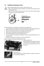
... back panel. 2. Hardware Installation Remove the metal slot cover from the power outlet before you begin to install an expansion card: • Make sure the motherboard supports the expansion card. After installing all expansion cards, replace the chassis cover(s). 6. Example: Installing and Removing a PCI Express Graphics Card: • Installing a Graphics Card...
... back panel. 2. Hardware Installation Remove the metal slot cover from the power outlet before you begin to install an expansion card: • Make sure the motherboard supports the expansion card. After installing all expansion cards, replace the chassis cover(s). 6. Example: Installing and Removing a PCI Express Graphics Card: • Installing a Graphics Card...
Manual
Page 18
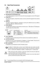
... your device and then remove it from the connector. Use this audio jack for line in jack. Do not rock it straight out from the motherboard. • When removing the cable, pull it side to side to 1 Gbps data rate. Hardware Installation - 18 - Connect a monitor that supports D-Sub connection to connect...
... your device and then remove it from the connector. Use this audio jack for line in jack. Do not rock it straight out from the motherboard. • When removing the cable, pull it side to side to 1 Gbps data rate. Hardware Installation - 18 - Connect a monitor that supports D-Sub connection to connect...

Manual
Page 19
... devices and your devices are compliant with the connectors you wish to connect. • Before installing the devices, be sure to the connector on the motherboard. - 19 -
... devices and your devices are compliant with the connectors you wish to connect. • Before installing the devices, be sure to the connector on the motherboard. - 19 -

Manual
Page 20
... - If a power supply is not connected, the computer will not start. To meet expansion requirements, it is turned off and all the components on the motherboard. Before connecting the power connector, first make sure the power supply is recommended that a power supply that does not provide the required power, the result...
... - If a power supply is not connected, the computer will not start. To meet expansion requirements, it is turned off and all the components on the motherboard. Before connecting the power connector, first make sure the power supply is recommended that a power supply that does not provide the required power, the result...
Manual
Page 21
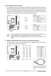
...DEBUG PORT PORT PORT • Be sure to connect fan cables to the fan headers to your CPU and system from overheating. The motherboard supports CPU fan speed control, which requires the use of the SATA cable to prevent your SATA hard drive. Do not place a... SATA2_0 7 7 7 1 1 1 SATA2_5 SATA2_4 SATA2_3 Pin No. 1 2 3 4 5 6 7 Definition GND TXP TXN GND RXN RXP GND - 21 - 3/4) CPU_FAN/SYS_FAN (Fan Headers) The motherboard has a 4-pin CPU fan header (CPU_FAN) and a 3-pin system fan header (SYS_FAN). Please connect the L-shaped end of a CPU fan with SATA 1.5Gb/s standard. Most...
...DEBUG PORT PORT PORT • Be sure to connect fan cables to the fan headers to your CPU and system from overheating. The motherboard supports CPU fan speed control, which requires the use of the SATA cable to prevent your SATA hard drive. Do not place a... SATA2_0 7 7 7 1 1 1 SATA2_5 SATA2_4 SATA2_3 Pin No. 1 2 3 4 5 6 7 Definition GND TXP TXN GND RXN RXP GND - 21 - 3/4) CPU_FAN/SYS_FAN (Fan Headers) The motherboard has a 4-pin CPU fan header (CPU_FAN) and a 3-pin system fan header (SYS_FAN). Please connect the L-shaped end of a CPU fan with SATA 1.5Gb/s standard. Most...
Manual
Page 24
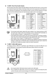
... conform to the USB bracket. Definition Pin No. For information about connecting the front panel audio module that has separated connectors on both of the motherboard header. Pin No. You may connect your computer and unplug the power cord from the power outlet to prevent damage to USB 2.0/1.1 specification. Definition 1 ... unable to activate AC'97 functionality via an optional USB bracket. Hardware Installation - 24 - Incorrect connection between the module connector and the motherboard header will be sure to turn off your chassis front panel audio module to this header.
... conform to the USB bracket. Definition Pin No. For information about connecting the front panel audio module that has separated connectors on both of the motherboard header. Pin No. You may connect your computer and unplug the power cord from the power outlet to prevent damage to USB 2.0/1.1 specification. Definition 1 ... unable to activate AC'97 functionality via an optional USB bracket. Hardware Installation - 24 - Incorrect connection between the module connector and the motherboard header will be sure to turn off your chassis front panel audio module to this header.


