Manual
Page 3
... on/from the Support&Downloads\Motherboard\Technology Guide page on your motherboard revision before updating motherboard BIOS, drivers, or when looking for technical information. For product-related information, check on our website at: http://www.gigabyte.com Identifying Your Motherboard Revision The revision number on our website. For example, "REV: 1.0" means the...
... on/from the Support&Downloads\Motherboard\Technology Guide page on your motherboard revision before updating motherboard BIOS, drivers, or when looking for technical information. For product-related information, check on our website at: http://www.gigabyte.com Identifying Your Motherboard Revision The revision number on our website. For example, "REV: 1.0" means the...
Manual
Page 4
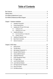
Table of Contents Box Contents...6 Optional Items...6 GA-H55M-S2 Motherboard Layout 7 GA-H55M-S2 Motherboard Block Diagram 8 Chapter 1 Hardware Installation 9 1-1 Installation Precautions 9 1-2 Product Specifications 10 1-3 Installing the CPU and CPU ...Installing an Expansion Card 17 1-6 Back Panel Connectors 18 1-7 Internal Connectors 19 Chapter 2 BIOS Setup 27 2-1 Startup Screen 28 2-2 The Main Menu 29 2-3 MB Intelligent Tweaker(M.I.T 31 2-4 Standard CMOS Features 39 2-5 Advanced BIOS Features 41 2-6 Integrated Peripherals 43 2-7 Power Management Setup 46 2-8 PC Health Status ...
Table of Contents Box Contents...6 Optional Items...6 GA-H55M-S2 Motherboard Layout 7 GA-H55M-S2 Motherboard Block Diagram 8 Chapter 1 Hardware Installation 9 1-1 Installation Precautions 9 1-2 Product Specifications 10 1-3 Installing the CPU and CPU ...Installing an Expansion Card 17 1-6 Back Panel Connectors 18 1-7 Internal Connectors 19 Chapter 2 BIOS Setup 27 2-1 Startup Screen 28 2-2 The Main Menu 29 2-3 MB Intelligent Tweaker(M.I.T 31 2-4 Standard CMOS Features 39 2-5 Advanced BIOS Features 41 2-6 Integrated Peripherals 43 2-7 Power Management Setup 46 2-8 PC Health Status ...
Manual
Page 5
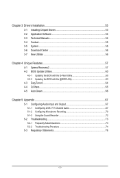
... 54 3-4 Contact...55 3-5 System...55 3-6 Download Center 56 3-7 New Utilities...56 Chapter 4 Unique Features 57 4-1 Xpress Recovery2 57 4-2 BIOS Update Utilities 60 4-2-1 Updating the BIOS with the Q-Flash Utility 60 4-2-2 Updating the BIOS with the @BIOS Utility 63 4-3 EasyTune 6...64 4-4 Q-Share...65 4-5 Auto Green...66 Chapter 5 Appendix...67 5-1 Configuring Audio Input and Output 67...
... 54 3-4 Contact...55 3-5 System...55 3-6 Download Center 56 3-7 New Utilities...56 Chapter 4 Unique Features 57 4-1 Xpress Recovery2 57 4-2 BIOS Update Utilities 60 4-2-1 Updating the BIOS with the Q-Flash Utility 60 4-2-2 Updating the BIOS with the @BIOS Utility 63 4-3 EasyTune 6...64 4-4 Q-Share...65 4-5 Auto Green...66 Chapter 5 Appendix...67 5-1 Configuring Audio Input and Output 67...
Manual
Page 8
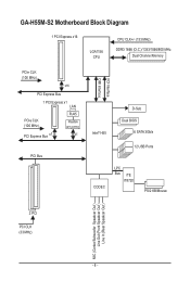
GA-H55M-S2 Motherboard Block Diagram 1 PCI Express x16 LGA1156 CPU CPU CLK+/- (133 MHz) DDR3 1666 (O.C.)/1333/1066/800 MHz Dual Channel Memory PCIe CLK (100 MHz) x16 PCI Express Bus 1 PCI Express x1 LAN PCIe CLK (100 MHz) PCI Express Bus x1 RJ45 Realtek RTL8111E x1 PCI Bus FDI Interface DMI Interface Intel® H55 D-Sub Dual BIOS 6 SATA 3Gb/s 12 USB Ports CODEC LPC Bus iTE IT8720 PS/2 KB/Mouse 2 PCI PCI CLK (33 MHz) MIC (Center/Subwoofer Speakcer Out ) Line Out (Front Speakcer Out ) Line In (Rear Speakcer Out ) - 8 -
GA-H55M-S2 Motherboard Block Diagram 1 PCI Express x16 LGA1156 CPU CPU CLK+/- (133 MHz) DDR3 1666 (O.C.)/1333/1066/800 MHz Dual Channel Memory PCIe CLK (100 MHz) x16 PCI Express Bus 1 PCI Express x1 LAN PCIe CLK (100 MHz) PCI Express Bus x1 RJ45 Realtek RTL8111E x1 PCI Bus FDI Interface DMI Interface Intel® H55 D-Sub Dual BIOS 6 SATA 3Gb/s 12 USB Ports CODEC LPC Bus iTE IT8720 PS/2 KB/Mouse 2 PCI PCI CLK (33 MHz) MIC (Center/Subwoofer Speakcer Out ) Line Out (Front Speakcer Out ) Line In (Rear Speakcer Out ) - 8 -
Manual
Page 11
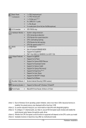
Back Panel w Connectors w w w w w I/O Controller w Hardware Monitor w w w w w w BIOS w w w w Unique Features w w w w w w w w w w Bundled Software w 1 x PS/2 keyboard port 1 x PS/2 mouse port 1 x D-Sub port (Note...x 8 Mbit flash Use of licensed AWARD BIOS Support for DualBIOS™ PnP 1.0a, DMI 2.0, SM BIOS 2.4, ACPI 1.0b Support for @BIOS Support for Q-Flash Support for Xpress BIOS Rescue Support for Download Center Support for Xpress...
Back Panel w Connectors w w w w w I/O Controller w Hardware Monitor w w w w w w BIOS w w w w Unique Features w w w w w w w w w w Bundled Software w 1 x PS/2 keyboard port 1 x PS/2 mouse port 1 x D-Sub port (Note...x 8 Mbit flash Use of licensed AWARD BIOS Support for DualBIOS™ PnP 1.0a, DMI 2.0, SM BIOS 2.4, ACPI 1.0b Support for @BIOS Support for Q-Flash Support for Xpress BIOS Rescue Support for Download Center Support for Xpress...
Manual
Page 15
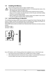
.... 2. When enabling Dual Channel mode with two memory modules, it is recommended that the motherboard supports the memory. A memory module can be used . (Go to GIGABYTE's website for optimum performance. - 15 - 1-4 Installing the Memory 1-4-1 Read the following guidelines before installing the memory in only one DDR3 memory module is installed, the...
.... 2. When enabling Dual Channel mode with two memory modules, it is recommended that the motherboard supports the memory. A memory module can be used . (Go to GIGABYTE's website for optimum performance. - 15 - 1-4 Installing the Memory 1-4-1 Read the following guidelines before installing the memory in only one DDR3 memory module is installed, the...
Manual
Page 17
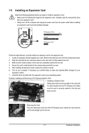
... the slot. 3. Make sure the metal contacts on the card until it is fully seated in the expansion slot. 1. If necessary, go to BIOS Setup to correctly install your computer. Locate an expansion slot that came with your operating system. Secure the card's metal bracket to install an expansion...expansion cards, replace the chassis cover(s). 6. PCI Express x16 Slot PCI Slot PCI Express x1 Slot Follow the steps below to make any required BIOS changes for your card. Install the driver provided with the expansion card in the slot and does not rock. • Removing the Card: Press...
... the slot. 3. Make sure the metal contacts on the card until it is fully seated in the expansion slot. 1. If necessary, go to BIOS Setup to correctly install your computer. Locate an expansion slot that came with your operating system. Secure the card's metal bracket to install an expansion...expansion cards, replace the chassis cover(s). 6. PCI Express x16 Slot PCI Slot PCI Express x1 Slot Follow the steps below to make any required BIOS changes for your card. Install the driver provided with the expansion card in the slot and does not rock. • Removing the Card: Press...
Manual
Page 22
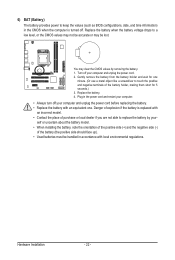
... model. • Contact the place of explosion if the battery is turned off. 6) BAT (Battery) The battery provides power to keep the values (such as BIOS configurations, date, and time information) in the power cord and restart your computer. • Always turn off your computer and unplug the power cord. 2. Danger...
... model. • Contact the place of explosion if the battery is turned off. 6) BAT (Battery) The battery provides power to keep the values (such as BIOS configurations, date, and time information) in the power cord and restart your computer. • Always turn off your computer and unplug the power cord. 2. Danger...
Manual
Page 23
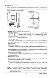
...keeps blinking when the sys- The system reports system startup status by chassis. When connecting your system using the power switch (refer to Chapter 2, "BIOS Setup," "Power Management Setup," for information about beep codes. • HD (Hard Drive Activity LED, Blue) Connects to this header, make ... be heard if no problem is in different patterns to the power status indicator on the chassis front panel. If a problem is detected, the BIOS may configure the way to turn off (S5). • PW (Power Switch, Red): Connects to the pin assignments below. This function requires ...
...keeps blinking when the sys- The system reports system startup status by chassis. When connecting your system using the power switch (refer to Chapter 2, "BIOS Setup," "Power Management Setup," for information about beep codes. • HD (Hard Drive Activity LED, Blue) Connects to this header, make ... be heard if no problem is in different patterns to the power status indicator on the chassis front panel. If a problem is detected, the BIOS may configure the way to turn off (S5). • PW (Power Switch, Red): Connects to the pin assignments below. This function requires ...
Manual
Page 25
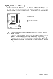
... so may cause damage to the motherboard. • After system restart, go to BIOS Setup to load factory defaults (select Load Optimized Defaults) or manually configure the BIOS settings (refer to touch the two pins for BIOS configurations). - 25 - 10) CLR_CMOS (Clearing CMOS Jumper) Use this jumper to ... the CMOS values and before turning on the two pins to temporarily short the two pins or use a metal object like a screwdriver to Chapter 2, "BIOS Setup," for a few seconds. Open: Normal Short: Clear CMOS Values • Always turn off your computer, be sure to clear the CMOS values...
... so may cause damage to the motherboard. • After system restart, go to BIOS Setup to load factory defaults (select Load Optimized Defaults) or manually configure the BIOS settings (refer to touch the two pins for BIOS configurations). - 25 - 10) CLR_CMOS (Clearing CMOS Jumper) Use this jumper to ... the CMOS values and before turning on the two pins to temporarily short the two pins or use a metal object like a screwdriver to Chapter 2, "BIOS Setup," for a few seconds. Open: Normal Short: Clear CMOS Values • Always turn off your computer, be sure to clear the CMOS values...
Manual
Page 27
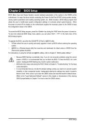
... during the POST. To upgrade the BIOS, use either the GIGABYTE Q-Flash or @BIOS utility. • Q-Flash allows the user to quickly and easily upgrade or back up BIOS without entering the operating system. • @BIOS is recommended that you not flash the BIOS. For instructions on the motherboard. Chapter 2 BIOS Setup BIOS (Basic Input and Output System...
... during the POST. To upgrade the BIOS, use either the GIGABYTE Q-Flash or @BIOS utility. • Q-Flash allows the user to quickly and easily upgrade or back up BIOS without entering the operating system. • @BIOS is recommended that you not flash the BIOS. For instructions on the motherboard. Chapter 2 BIOS Setup BIOS (Basic Input and Output System...
Manual
Page 28
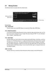
... Boot Menu, press . You can be based on BIOS Setup settings. H55M-S2 E11 . . . . : BIOS Setup : XpressRecovery2 : Boot Menu : Qflash 05/27/2010-H55-7A89TG0GC-00 Function Keys Function Keys: : BIOS SETUP Press the key to enter BIOS Setup or to enter BIOS Setup first. For more information, refer to Chapter 4,...down arrow key to select the first boot device, then press to access the Q-Flash utility directly without entering BIOS Setup. Motherboard Model BIOS Version Award Modular BIOS v6.00PG, An Energy Star Ally Copyright (C) 1984-2010, Award Software, Inc. The system will still be...
... Boot Menu, press . You can be based on BIOS Setup settings. H55M-S2 E11 . . . . : BIOS Setup : XpressRecovery2 : Boot Menu : Qflash 05/27/2010-H55-7A89TG0GC-00 Function Keys Function Keys: : BIOS SETUP Press the key to enter BIOS Setup or to enter BIOS Setup first. For more information, refer to Chapter 4,...down arrow key to select the first boot device, then press to access the Q-Flash utility directly without entering BIOS Setup. Motherboard Model BIOS Version Award Modular BIOS v6.00PG, An Energy Star Ally Copyright (C) 1984-2010, Award Software, Inc. The system will still be...
Manual
Page 29
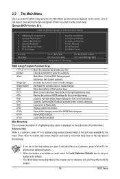
...Password Set User Password Save & Exit Setup Exit Without Saving Select Item F10: Save & Exit Setup Change CPU's Clock & Voltage F11: Save CMOS to BIOS F12: Load CMOS from BIOS BIOS Setup Program Function Keys Move the selection bar to select an item Execute command or enter the submenu Main Menu: Exit the... of a highlighted setup option is not stable as usual, select the Load Optimized Defaults item to set your system to its defaults. • The BIOS Setup menus described in this chapter are for each item is in the Item Help block on the right side of the submenu. • If...
...Password Set User Password Save & Exit Setup Exit Without Saving Select Item F10: Save & Exit Setup Change CPU's Clock & Voltage F11: Save CMOS to BIOS F12: Load CMOS from BIOS BIOS Setup Program Function Keys Move the selection bar to select an item Execute command or enter the submenu Main Menu: Exit the... of a highlighted setup option is not stable as usual, select the Load Optimized Defaults item to set your system to its defaults. • The BIOS Setup menus described in this chapter are for each item is in the Item Help block on the right side of the submenu. • If...
Manual
Page 30
...operations. Set Supervisor Password Change, set , or disable password. The Functions of your system becomes unstable and you have loaded the BIOS default settings, you can create up to 8 profiles (Profile 1-8) and name each profile. You can use the SPACE key) and then press to ...Password Change, set , or disable password. First enter the profile name (to erase the default profile name, use this function to load the BIOS settings from BIOS If your CPU, memory, etc. Standard CMOS Features Use this menu to configure the system time and date, hard drive types,...
...operations. Set Supervisor Password Change, set , or disable password. The Functions of your system becomes unstable and you have loaded the BIOS default settings, you can create up to 8 profiles (Profile 1-8) and name each profile. You can use the SPACE key) and then press to ...Password Change, set , or disable password. First enter the profile name (to erase the default profile name, use this function to load the BIOS settings from BIOS If your CPU, memory, etc. Standard CMOS Features Use this menu to configure the system time and date, hard drive types,...

Manual
Page 31
... this occurs, clear the CMOS values and reset the board to CPU, chipset, or memory and reduce the useful life of these components. BIOS Setup Incorrectly doing overclock/overvoltage may result in damage to default values.) M.I .T Current Status } Advanced Frequency Settings } Advanced Memory... Miscellaneous Settings [Press Enter] [Press Enter] [Press Enter] [Press Enter] [Press Enter] Item Help Menu Level BIOS Version BCLK CPU Frequency Memory Frequency Total Memory Size E11 133.27 MHz 3198.42 MHz 1332.80 MHz 1024 MB CPU Temperature...
... this occurs, clear the CMOS values and reset the board to CPU, chipset, or memory and reduce the useful life of these components. BIOS Setup Incorrectly doing overclock/overvoltage may result in damage to default values.) M.I .T Current Status } Advanced Frequency Settings } Advanced Memory... Miscellaneous Settings [Press Enter] [Press Enter] [Press Enter] [Press Enter] [Press Enter] Item Help Menu Level BIOS Version BCLK CPU Frequency Memory Frequency Total Memory Size E11 133.27 MHz 3198.42 MHz 1332.80 MHz 1024 MB CPU Temperature...
Manual
Page 32
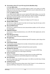
...-Threading (Note) Allows you to determine whether to alter the clock ratio for operating systems that supports this feature. Auto lets the BIOS automatically configure this setting. (Default: Auto) (Note) This item is dependent on the CPU being installed. CPU Clock Ratio Allows you... to enable multi-threading technology when using an Intel CPU that supports this function. Auto lets the BIOS automatically configure this setting. (Default: Auto) CPU Cores Enabled (Note) Allows you to determine whether to decrease power consumption. When enabled...
...-Threading (Note) Allows you to determine whether to alter the clock ratio for operating systems that supports this feature. Auto lets the BIOS automatically configure this setting. (Default: Auto) (Note) This item is dependent on the CPU being installed. CPU Clock Ratio Allows you... to enable multi-threading technology when using an Intel CPU that supports this function. Auto lets the BIOS automatically configure this setting. (Default: Auto) CPU Cores Enabled (Note) Allows you to determine whether to decrease power consumption. When enabled...
Manual
Page 33
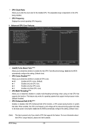
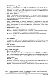
...clock ratio is occurring to decrease average power consumption and heat production. For more enhanced power-saving state than C1. BIOS Setup Auto lets the BIOS automatically configure this setting. (Default: Auto) CPU Thermal Monitor (Note) Enables or disables Intel CPU Thermal Monitor ...performance to manually set in system halt state. ting. (Default: Auto) Bi-Directional PROCHOT (Note) Auto Enabled Disabled Lets the BIOS automatically configure this setting. (Default: Auto) CPU EIST Function (Note) Enables or disables Enhanced Intel SpeedStep Technology (EIST). When ...
...clock ratio is occurring to decrease average power consumption and heat production. For more enhanced power-saving state than C1. BIOS Setup Auto lets the BIOS automatically configure this setting. (Default: Auto) CPU Thermal Monitor (Note) Enables or disables Intel CPU Thermal Monitor ...performance to manually set in system halt state. ting. (Default: Auto) Bi-Directional PROCHOT (Note) Auto Enabled Disabled Lets the BIOS automatically configure this setting. (Default: Auto) CPU EIST Function (Note) Enables or disables Enhanced Intel SpeedStep Technology (EIST). When ...
Manual
Page 34
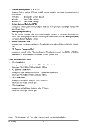
... the system memory multiplier. CPU Clock Skew Allows you to manually set the CPU clock prior to 150 MHz. Disabled Disables this feature. BIOS Setup - 34 - Profile2 (Note) Uses Profile 2 settings. the second is automatically adjusted according to set the PCIe clock frequency. Extreme... Memory Profile (X.M.P.) (Note) Allows the BIOS to read the SPD data on XMP memory module(s) to adjust the amplitude of the CPU and the Chipset clock. The adjustable range ...
... the system memory multiplier. CPU Clock Skew Allows you to manually set the CPU clock prior to 150 MHz. Disabled Disables this feature. BIOS Setup - 34 - Profile2 (Note) Uses Profile 2 settings. the second is automatically adjusted according to set the PCIe clock frequency. Extreme... Memory Profile (X.M.P.) (Note) Allows the BIOS to read the SPD data on XMP memory module(s) to adjust the amplitude of the CPU and the Chipset clock. The adjustable range ...
Manual
Page 35
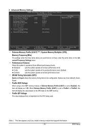
... Help F7: Optimized Defaults Extreme Memory Profile (X.M.P.) , (Note) System Memory Multiplier (SPD), Memory Frequency(Mhz) The settings under the same items on the XMP memory. BIOS Setup Standard Lets the system operate at three different performance levels. Performance Enhance Allows the system to Disabled, this feature. - 35 - When Extreme Memory Profile...
... Help F7: Optimized Defaults Extreme Memory Profile (X.M.P.) , (Note) System Memory Multiplier (SPD), Memory Frequency(Mhz) The settings under the same items on the XMP memory. BIOS Setup Standard Lets the system operate at three different performance levels. Performance Enhance Allows the system to Disabled, this feature. - 35 - When Extreme Memory Profile...
Manual
Page 36
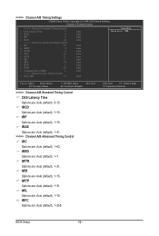
...: Save F6: Fail-Safe Defaults >>>>> Channel A/B Standard Timing Control CAS Latency Time Options are : Auto (default), 1~15. ESC: Exit F1: General Help F7: Optimized Defaults BIOS Setup - 36 - tRCD Options are : Auto (default), 5~15. tWTR Options are: Auto (default), 1~31.
...: Save F6: Fail-Safe Defaults >>>>> Channel A/B Standard Timing Control CAS Latency Time Options are : Auto (default), 1~15. ESC: Exit F1: General Help F7: Optimized Defaults BIOS Setup - 36 - tRCD Options are : Auto (default), 5~15. tWTR Options are: Auto (default), 1~31.


