Manual
Page 4
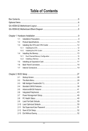
Table of Contents Box Contents...6 Optional Items...6 GA-H55M-S2 Motherboard Layout 7 GA-H55M-S2 Motherboard Block Diagram 8 Chapter 1 Hardware Installation 9 1-1 Installation Precautions 9 1-2 Product Specifications 10 1-3 Installing the CPU and CPU Cooler 12 1-3-1 Installing the CPU 12 1-3-2 Installing the CPU Cooler 14 1-4 Installing the Memory 15 1-4-1 Dual Channel Memory Configuration 15 1-4-2 Installing a Memory 16 1-5 Installing an Expansion Card 17 1-6 Back...
Table of Contents Box Contents...6 Optional Items...6 GA-H55M-S2 Motherboard Layout 7 GA-H55M-S2 Motherboard Block Diagram 8 Chapter 1 Hardware Installation 9 1-1 Installation Precautions 9 1-2 Product Specifications 10 1-3 Installing the CPU and CPU Cooler 12 1-3-1 Installing the CPU 12 1-3-2 Installing the CPU Cooler 14 1-4 Installing the Memory 15 1-4-1 Dual Channel Memory Configuration 15 1-4-2 Installing a Memory 16 1-5 Installing an Expansion Card 17 1-6 Back...
Manual
Page 8
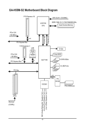
GA-H55M-S2 Motherboard Block Diagram 1 PCI Express x16 LGA1156 CPU CPU CLK+/- (133 MHz) DDR3 1666 (O.C.)/1333/1066/800 MHz Dual Channel Memory PCIe CLK (100 MHz) x16 PCI Express Bus 1 PCI Express x1 LAN PCIe CLK (100 MHz) PCI Express Bus x1 RJ45 Realtek RTL8111E x1 PCI Bus FDI Interface DMI Interface Intel® H55 D-Sub Dual BIOS 6 SATA 3Gb/s 12 USB Ports CODEC LPC Bus iTE IT8720 PS/2 KB/Mouse 2 PCI PCI CLK (33 MHz) MIC (Center/Subwoofer Speakcer Out ) Line Out (Front Speakcer Out ) Line In (Rear Speakcer Out ) - 8 -
GA-H55M-S2 Motherboard Block Diagram 1 PCI Express x16 LGA1156 CPU CPU CLK+/- (133 MHz) DDR3 1666 (O.C.)/1333/1066/800 MHz Dual Channel Memory PCIe CLK (100 MHz) x16 PCI Express Bus 1 PCI Express x1 LAN PCIe CLK (100 MHz) PCI Express Bus x1 RJ45 Realtek RTL8111E x1 PCI Bus FDI Interface DMI Interface Intel® H55 D-Sub Dual BIOS 6 SATA 3Gb/s 12 USB Ports CODEC LPC Bus iTE IT8720 PS/2 KB/Mouse 2 PCI PCI CLK (33 MHz) MIC (Center/Subwoofer Speakcer Out ) Line Out (Front Speakcer Out ) Line In (Rear Speakcer Out ) - 8 -
Manual
Page 9
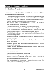
... allow screws to come in a high-temperature environment. • Turning on the computer power during the installation process can become damaged as a motherboard, CPU or memory. Prior to installation, carefully read the user's manual and follow these procedures: • Prior to installation, do not remove or break motherboard S/N (Serial Number) sticker...
... allow screws to come in a high-temperature environment. • Turning on the computer power during the installation process can become damaged as a motherboard, CPU or memory. Prior to installation, carefully read the user's manual and follow these procedures: • Prior to installation, do not remove or break motherboard S/N (Serial Number) sticker...
Manual
Page 10
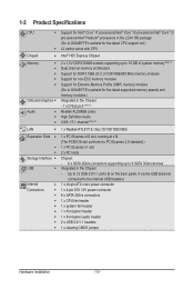
...; 2 x 1.5V DDR3 DIMM sockets supporting up to 16 GB of system memory (Note 1) Dual channel memory architecture Support for DDR3 1666 (O.C.)/1333/1066/800 MHz memory modules Support for non-ECC memory modules Support for Extreme Memory Profile (XMP) memory modules (Go to GIGABYTE's website for the latest supported memory speeds and memory modules.) Integrated in the Chipset -
...; 2 x 1.5V DDR3 DIMM sockets supporting up to 16 GB of system memory (Note 1) Dual channel memory architecture Support for DDR3 1666 (O.C.)/1333/1066/800 MHz memory modules Support for non-ECC memory modules Support for Extreme Memory Profile (XMP) memory modules (Go to GIGABYTE's website for the latest supported memory speeds and memory modules.) Integrated in the Chipset -
Manual
Page 11
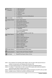
... Factor w MicroATX Form Factor; 24.4cm x 21.0cm (Note 1) Due to Windows 32-bit operating system limitation, when more than 4 GB of physical memory is installed, the actual memory size displayed will be less than 4 GB. (Note 2) To use the onboard D-Sub port, you must install an Intel CPU with integrated graphics...
... Factor w MicroATX Form Factor; 24.4cm x 21.0cm (Note 1) Due to Windows 32-bit operating system limitation, when more than 4 GB of physical memory is installed, the actual memory size displayed will be less than 4 GB. (Note 2) To use the onboard D-Sub port, you must install an Intel CPU with integrated graphics...
Manual
Page 12
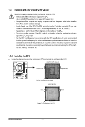
... 12 - If you wish to set beyond the standard specifications, please do so according to your hardware specifications including the CPU, graphics card, memory, hard drive, etc. 1-3-1 Installing the CPU A. The CPU cannot be set the frequency beyond hardware specifications since it does not meet the ... CPU socket and the notches on the computer if the CPU cooler is not recommended that the motherboard supports the CPU. (Go to GIGABYTE's website for the peripherals. 1-3 Installing the CPU and CPU Cooler Read the following guidelines before you begin to install the CPU: •...
... 12 - If you wish to set beyond the standard specifications, please do so according to your hardware specifications including the CPU, graphics card, memory, hard drive, etc. 1-3-1 Installing the CPU A. The CPU cannot be set the frequency beyond hardware specifications since it does not meet the ... CPU socket and the notches on the computer if the CPU cooler is not recommended that the motherboard supports the CPU. (Go to GIGABYTE's website for the peripherals. 1-3 Installing the CPU and CPU Cooler Read the following guidelines before you begin to install the CPU: •...
Manual
Page 15
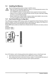
... prevent hardware damage. • Memory modules have a foolproof design. After the memory is installed. 2. 1-4 Installing the Memory 1-4-1 Read the following guidelines before installing the memory in only one memory socket as following: Channel 0: DDR3_1 Channel 1: DDR3_2 DDR3_1 DDR3_2 Due to CPU limitations, read the following guidelines before installing the memory to GIGABYTE's website for optimum performance. - 15...
... prevent hardware damage. • Memory modules have a foolproof design. After the memory is installed. 2. 1-4 Installing the Memory 1-4-1 Read the following guidelines before installing the memory in only one memory socket as following: Channel 0: DDR3_1 Channel 1: DDR3_2 DDR3_1 DDR3_2 Due to CPU limitations, read the following guidelines before installing the memory to GIGABYTE's website for optimum performance. - 15...
Manual
Page 16
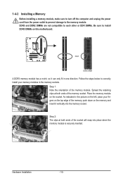
...socket. As indicated in the picture on the left, place your memory modules in one direction. Step 2: The clips at both ends of the memory socket. Place the memory module on the memory and insert it can only fit in the memory sockets. Hardware Installation - 16 - DDR3 and DDR2 DIMMs are... not compatible to each other or DDR DIMMs. Be sure to correctly install your fingers on the top edge of the memory module. 1-4-2 Installing a Memory Before installing a memory module, make sure to turn off the computer and unplug the power cord from the power outlet to prevent damage to...
...socket. As indicated in the picture on the left, place your memory modules in one direction. Step 2: The clips at both ends of the memory socket. Place the memory module on the memory and insert it can only fit in the memory sockets. Hardware Installation - 16 - DDR3 and DDR2 DIMMs are... not compatible to each other or DDR DIMMs. Be sure to correctly install your fingers on the top edge of the memory module. 1-4-2 Installing a Memory Before installing a memory module, make sure to turn off the computer and unplug the power cord from the power outlet to prevent damage to...
Manual
Page 30
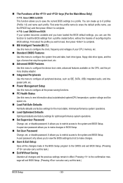
... profile. First enter the profile name (to erase the default profile name, use this function to load the BIOS settings from BIOS If your CPU, memory, etc. Standard CMOS Features Use this menu to configure the system time and date, hard drive types, floppy disk drive types, and the type...
... profile. First enter the profile name (to erase the default profile name, use this function to load the BIOS settings from BIOS If your CPU, memory, etc. Standard CMOS Features Use this menu to configure the system time and date, hard drive types, floppy disk drive types, and the type...

Manual
Page 31
...Ratio QPI Link Speed >>>>> Standard Clock Control Base Clock(BCLK) Control x BCLK Frequency (Mhz) Extreme Memory Profile (X.M.P.) (Note) System Memory Multiplier (SPD) Memory Frequency (Mhz) 1333 Internal Graphics Clock 733 PCI Express Frequency (Mhz) >>>>> Advanced Clock Control CPU Clock... [Press Enter] [Press Enter] [Press Enter] Item Help Menu Level BIOS Version BCLK CPU Frequency Memory Frequency Total Memory Size E11 133.27 MHz 3198.42 MHz 1332.80 MHz 1024 MB CPU Temperature PCH Temperature 45oC 40oC Vcore...
...Ratio QPI Link Speed >>>>> Standard Clock Control Base Clock(BCLK) Control x BCLK Frequency (Mhz) Extreme Memory Profile (X.M.P.) (Note) System Memory Multiplier (SPD) Memory Frequency (Mhz) 1333 Internal Graphics Clock 733 PCI Express Frequency (Mhz) >>>>> Advanced Clock Control CPU Clock... [Press Enter] [Press Enter] [Press Enter] Item Help Menu Level BIOS Version BCLK CPU Frequency Memory Frequency Total Memory Size E11 133.27 MHz 3198.42 MHz 1332.80 MHz 1024 MB CPU Temperature PCH Temperature 45oC 40oC Vcore...
Manual
Page 34
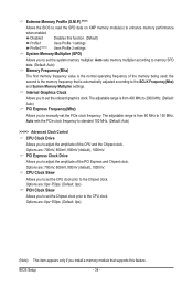
... 150 MHz. PCI Express Clock Drive Allows you to the Chipset clock. The adjustable range is automatically adjusted according to enhance memory performance when enabled. Options are : 700mV, 800mV, 900mV (default), 1000mV. Disabled Disables this feature. Options are : 700mV, 800mV, 900mV... (default), 1000mV. System Memory Multiplier (SPD) Allows you to set the Chipset clock prior to set the onboard graphics clock. Options are : 0ps~750ps. (Default: 0ps...
... 150 MHz. PCI Express Clock Drive Allows you to the Chipset clock. The adjustable range is automatically adjusted according to enhance memory performance when enabled. Options are : 700mV, 800mV, 900mV (default), 1000mV. Disabled Disables this feature. Options are : 700mV, 800mV, 900mV... (default), 1000mV. System Memory Multiplier (SPD) Allows you to set the Chipset clock prior to set the onboard graphics clock. Options are : 0ps~750ps. (Default: 0ps...
Manual
Page 35
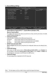
...Standard Lets the system operate at its basic performance level. DRAM Timing Selectable (SPD) Quick and Expert allows the memory timing items to operate at three different performance levels. BIOS Setup Turbo Lets the system operate at its good performance...Profile2, this item will display as 1.5V. Advanced Memory Settings CMOS Setup Utility-Copyright (C) 1984-2010 Award Software Advanced Memory Settings Extreme Memory Profile (X.M.P.) (Note) System Memory Multiplier (SPD) Memory Frequency (Mhz) 1333 Performance Enhance DRAM Timing Selectable (SPD) Profile...
...Standard Lets the system operate at its basic performance level. DRAM Timing Selectable (SPD) Quick and Expert allows the memory timing items to operate at three different performance levels. BIOS Setup Turbo Lets the system operate at its good performance...Profile2, this item will display as 1.5V. Advanced Memory Settings CMOS Setup Utility-Copyright (C) 1984-2010 Award Software Advanced Memory Settings Extreme Memory Profile (X.M.P.) (Note) System Memory Multiplier (SPD) Memory Frequency (Mhz) 1333 Performance Enhance DRAM Timing Selectable (SPD) Profile...
Manual
Page 38
...Default: Enabled) CMOS Setup Utility-Copyright (C) 1984-2010 Award Software MB Intelligent Tweaker(M.I.T.) } M.I.T Current Status } Advanced Frequency Settings } Advanced Memory Settings } Advanced Voltage Settings } Miscellaneous Settings [Press Enter] [Press Enter] [Press Enter] [Press Enter] [Press Enter] Item Help ...Menu Level BIOS Version BCLK CPU Frequency Memory Frequency Total Memory Size E11 133.37 MHz 3067.78 MHz 1333.75 MHz 1024 MB CPU Temperature PCH Temperature 23.0oC 41...
...Default: Enabled) CMOS Setup Utility-Copyright (C) 1984-2010 Award Software MB Intelligent Tweaker(M.I.T.) } M.I.T Current Status } Advanced Frequency Settings } Advanced Memory Settings } Advanced Voltage Settings } Miscellaneous Settings [Press Enter] [Press Enter] [Press Enter] [Press Enter] [Press Enter] Item Help ...Menu Level BIOS Version BCLK CPU Frequency Memory Frequency Total Memory Size E11 133.37 MHz 3067.78 MHz 1333.75 MHz 1024 MB CPU Temperature PCH Temperature 23.0oC 41...
Manual
Page 39
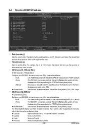
... } IDE Channel 1 Master } IDE Channel 1 Slave } IDE Channel 2 Master } IDE Channel 3 Master [None] [None] [None] [None] [None] [None] Halt On [All, But Keyboard] Base Memory Extended Memory Total Memory 640K 1022M 1024M Move Enter: Select F5: Previous Values +/-/PU/PD: Value F10: Save F6: Fail-Safe Defaults ESC: Exit F1: General Help F7...
... } IDE Channel 1 Master } IDE Channel 1 Slave } IDE Channel 2 Master } IDE Channel 3 Master [None] [None] [None] [None] [None] [None] Halt On [All, But Keyboard] Base Memory Extended Memory Total Memory 640K 1022M 1024M Move Enter: Select F5: Previous Values +/-/PU/PD: Value F10: Save F6: Fail-Safe Defaults ESC: Exit F1: General Help F7...
Manual
Page 40
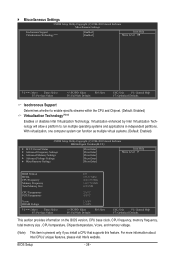
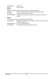
... of sectors. BIOS Setup - 40 - All Errors Whenever the BIOS detects a non-fatal error the system boot will not stop . Base Memory Also called conventional memory. Total Memory The total amount of memory installed on the system. Landing Zone Sector Halt On Landing zone. Allows you to determine whether the system will be reserved... for an error during the POST. All, But Keyboard The system boot will not stop for a keyboard error but stop for all other errors. (Default) Memory These fields are read-only and are determined by the BIOS POST.
... of sectors. BIOS Setup - 40 - All Errors Whenever the BIOS detects a non-fatal error the system boot will not stop . Base Memory Also called conventional memory. Total Memory The total amount of memory installed on the system. Landing Zone Sector Halt On Landing zone. Allows you to determine whether the system will be reserved... for an error during the POST. All, But Keyboard The system boot will not stop for a keyboard error but stop for all other errors. (Default) Memory These fields are read-only and are determined by the BIOS POST.
Manual
Page 41
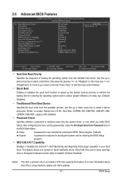
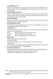
... Advanced BIOS Features } Hard Disk Boot Priority Quick Boot First Boot Device Second Boot Device Third Boot Device Password Check HDD S.M.A.R.T. to 3 (Note) No-Execute Memory Protect (Note) Delay For HDD (Secs) Backup BIOS Image to deliver greater efficiency for GTT] Item Help Menu Level Move Enter: Select F5: Previous...
... Advanced BIOS Features } Hard Disk Boot Priority Quick Boot First Boot Device Second Boot Device Third Boot Device Password Check HDD S.M.A.R.T. to 3 (Note) No-Execute Memory Protect (Note) Delay For HDD (Secs) Backup BIOS Image to deliver greater efficiency for GTT] Item Help Menu Level Move Enter: Select F5: Previous...
Manual
Page 42
...HDD Allows the system to copy the BIOS image file to initialize the hard drive as Windows NT4.0. (Default: Disabled) No-Execute Memory Protect (Note) Enables or disables Intel Execute Disable Bit function. Onboard VGA Enables or disables the onboard graphics function. If you to...HDD (Secs) Allows you install a CPU that supports this image file. (Default: Disabled) Init Display First Specifies the first initiation of system memory allocated solely for display. MS-DOS, for example, will be recovered from this feature. The adjustable range is from the installed PCI graphics card...
...HDD Allows the system to copy the BIOS image file to initialize the hard drive as Windows NT4.0. (Default: Disabled) No-Execute Memory Protect (Note) Enables or disables Intel Execute Disable Bit function. Onboard VGA Enables or disables the onboard graphics function. If you to...HDD (Secs) Allows you install a CPU that supports this image file. (Default: Disabled) Init Display First Specifies the first initiation of system memory allocated solely for display. MS-DOS, for example, will be recovered from this feature. The adjustable range is from the installed PCI graphics card...
Manual
Page 47
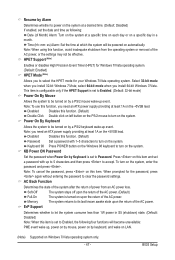
... of the system after the return of power from the operating system or removal of the AC power, or the settings may not be effective. Memory The system returns to its last known awake state upon the return of the AC power. (Default) Full-On The system is set to Password...
... of the system after the return of power from the operating system or removal of the AC power, or the settings may not be effective. Memory The system returns to its last known awake state upon the return of the AC power. (Default) Full-On The system is set to Password...
Manual
Page 57
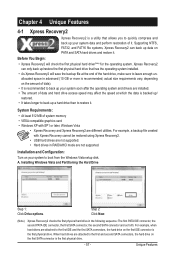
A. When hard drives are installed. • The amount of data and hard drive access speed may affect the speed at the end of system memory • VESA compatible graphics card • Windows XP with Xpress Recovery cannot be restored using Xpress Recovery2. • USB hard drives are different utilities. Supporting ...
A. When hard drives are installed. • The amount of data and hard drive access speed may affect the speed at the end of system memory • VESA compatible graphics card • Windows XP with Xpress Recovery cannot be restored using Xpress Recovery2. • USB hard drives are different utilities. Supporting ...
Manual
Page 64
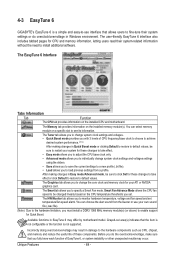
... information on the installed CPU and motherboard. The Graphics tab allows you to change the core clock and memory clock for your system for CPU and memory information, letting users read their system settings or do the overclock/overvoltage, make sure that you to monitor... you do overclock/overvoltage in Easy mode/Advanced mode, be changed linearly based on a specific slot to install additional software. 4-3 EasyTune 6 GIGABYTE's EasyTune 6 is not supported. You can choose the alert sound from a profile. The Tuner tab allows you to change system clock settings...
... information on the installed CPU and motherboard. The Graphics tab allows you to change the core clock and memory clock for your system for CPU and memory information, letting users read their system settings or do the overclock/overvoltage, make sure that you to monitor... you do overclock/overvoltage in Easy mode/Advanced mode, be changed linearly based on a specific slot to install additional software. 4-3 EasyTune 6 GIGABYTE's EasyTune 6 is not supported. You can choose the alert sound from a profile. The Tuner tab allows you to change system clock settings...


