Manual
Page 3
...this manual may be reproduced, copied, translated, transmitted, or published in the use of GIGABYTE. Check your motherboard looks like this manual may be made by any means without prior...to the specifications and features in this manual are legally registered to assist in any form or by GIGABYTE without GIGABYTE's prior written permission. In order to their respective owners. All rights reserved. Disclaimer ...our website at: http://www.gigabyte.com Identifying Your Motherboard Revision The revision number on your motherboard revision before updating motherboard...
...this manual may be reproduced, copied, translated, transmitted, or published in the use of GIGABYTE. Check your motherboard looks like this manual may be made by any means without prior...to the specifications and features in this manual are legally registered to assist in any form or by GIGABYTE without GIGABYTE's prior written permission. In order to their respective owners. All rights reserved. Disclaimer ...our website at: http://www.gigabyte.com Identifying Your Motherboard Revision The revision number on your motherboard revision before updating motherboard...
Manual
Page 4
...GA-G41MT-S2 Motherboard Layout 5 Chapter 1 Hardware Installation 6 1-1 Installation Precautions 6 1-2 Product Specifications 7 1-3 Installing the CPU and CPU Cooler 9 1-3-1 Installing the CPU...9 1-4 Installing the Memory 10 1-4-1 Dual Channel Memory Configuration 10 1-5 Installing an Expansion Card 10 1-6 Back Panel Connectors 11 1-7 Internal Connectors 12 Chapter 2 BIOS... Setup 19 2-1 Startup Screen 19 2-2 The Main Menu 19 2-3 MB Intelligent Tweaker(M.I.T 20 2-4 Standard CMOS Features 26 2-5 Advanced BIOS Features 27 2-6 Advanced Chipset ...
...GA-G41MT-S2 Motherboard Layout 5 Chapter 1 Hardware Installation 6 1-1 Installation Precautions 6 1-2 Product Specifications 7 1-3 Installing the CPU and CPU Cooler 9 1-3-1 Installing the CPU...9 1-4 Installing the Memory 10 1-4-1 Dual Channel Memory Configuration 10 1-5 Installing an Expansion Card 10 1-6 Back Panel Connectors 11 1-7 Internal Connectors 12 Chapter 2 BIOS... Setup 19 2-1 Startup Screen 19 2-2 The Main Menu 19 2-3 MB Intelligent Tweaker(M.I.T 20 2-4 Standard CMOS Features 26 2-5 Advanced BIOS Features 27 2-6 Advanced Chipset ...
Manual
Page 8
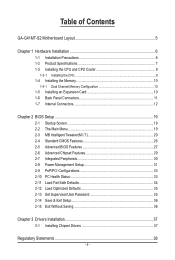
...port w 4 x USB 2.0/1.1 ports w 1 x RJ-45 port w 3 x audio jacks (Line In/Line Out/Microphone) I/O w iTE IT8718 Hardware Monitor w w w w w w BIOS w w w w Unique Features w w w w w w w w w w w System voltage detection CPU/System temperature detection CPU/System fan speed detection CPU overheating warning CPU/System fan fail ... w Micro ATX Form Factor; 24.4cm x 19.4cm * GIGABYTE reserves the right to make any changes to the hardware limitation, you install. 2 x 8 Mbit flash...
...port w 4 x USB 2.0/1.1 ports w 1 x RJ-45 port w 3 x audio jacks (Line In/Line Out/Microphone) I/O w iTE IT8718 Hardware Monitor w w w w w w BIOS w w w w Unique Features w w w w w w w w w w w System voltage detection CPU/System temperature detection CPU/System fan speed detection CPU overheating warning CPU/System fan fail ... w Micro ATX Form Factor; 24.4cm x 19.4cm * GIGABYTE reserves the right to make any changes to the hardware limitation, you install. 2 x 8 Mbit flash...
Manual
Page 10
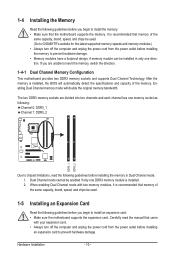
... and supports Dual Channel Technology. It is installed. 2. Hardware Installation - 10 - Dual Channel mode cannot be used . (Go to GIGABYTE's website for the latest supported memory speeds and memory modules.) • Always turn off the computer and unplug the power cord from the...guidelines before you begin to install the memory: • Make sure that came with two memory modules, it is installed, the BIOS will double the original memory bandwidth. Enabling Dual Channel memory mode will automatically detect the specifications and capacity of the same capacity, ...
... and supports Dual Channel Technology. It is installed. 2. Hardware Installation - 10 - Dual Channel mode cannot be used . (Go to GIGABYTE's website for the latest supported memory speeds and memory modules.) • Always turn off the computer and unplug the power cord from the...guidelines before you begin to install the memory: • Make sure that came with two memory modules, it is installed, the BIOS will double the original memory bandwidth. Enabling Dual Channel memory mode will automatically detect the specifications and capacity of the same capacity, ...
Manual
Page 15
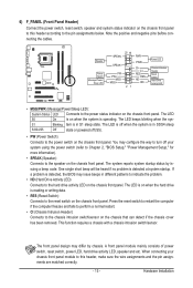
Speaker Power Switch Message/Power/ Sleep LED G.QBOFM 20 19 SPEAK- If a problem is detected, the BIOS may issue beeps in different patterns to indicate the problem. • HD (Hard Drive Activity LED) Connects to the speaker on the chassis front... panel. This function requires a chassis with a chassis intrusion switch/sensor. When connecting your system using the power switch (refer to Chapter 2, "BIOS Setup," "Power Management Setup," for more information). • SPEAK (Speaker): Connects to the hard drive activity LED on the chassis front panel. You may ...
Speaker Power Switch Message/Power/ Sleep LED G.QBOFM 20 19 SPEAK- If a problem is detected, the BIOS may issue beeps in different patterns to indicate the problem. • HD (Hard Drive Activity LED) Connects to the speaker on the chassis front... panel. This function requires a chassis with a chassis intrusion switch/sensor. When connecting your system using the power switch (refer to Chapter 2, "BIOS Setup," "Power Management Setup," for more information). • SPEAK (Speaker): Connects to the hard drive activity LED on the chassis front panel. You may ...

Manual
Page 17
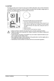
...values and before turning on the two pins to temporarily short the two pins or use a metal object like a screwdriver to Chapter 2, "BIOS Setup," for a few seconds. Failure to do so may cause damage to the motherboard. • After system restart, go to... BIOS Setup to load factory defaults (select Load Optimized Defaults) or manually configure the BIOS settings (refer to touch the two pins for BIOS configurations). - 17 - Hardware Installation date information and BIOS configurations) and reset the CMOS values to clear the CMOS...
...values and before turning on the two pins to temporarily short the two pins or use a metal object like a screwdriver to Chapter 2, "BIOS Setup," for a few seconds. Failure to do so may cause damage to the motherboard. • After system restart, go to... BIOS Setup to load factory defaults (select Load Optimized Defaults) or manually configure the BIOS settings (refer to touch the two pins for BIOS configurations). - 17 - Hardware Installation date information and BIOS configurations) and reset the CMOS values to clear the CMOS...
Manual
Page 18
... cord. 2. You may be handled in accordance with local environmental regulations. Replace the battery when the battery voltage drops to keep the values (such as BIOS configurations, date, and time information) in the power cord and restart your computer. • Always turn off your computer and unplug the power cord before...
... cord. 2. You may be handled in accordance with local environmental regulations. Replace the battery when the battery voltage drops to keep the values (such as BIOS configurations, date, and time information) in the power cord and restart your computer. • Always turn off your computer and unplug the power cord before...
Manual
Page 19
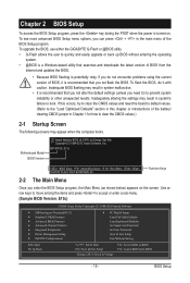
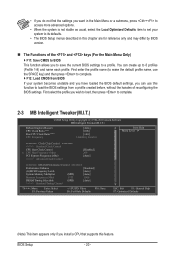
To upgrade the BIOS, use either the GIGABYTE Q-Flash or @BIOS utility. • Q-Flash allows the user to quickly and easily upgrade or back up BIOS without entering the operating system. • @BIOS is a Windows-based utility that searches and downloads the latest version of the battery/ clearing ... & Exit Setup Change CPU's Clock & Voltage F11: Save CMOS to BIOS F12: Load CMOS from the Internet and updates the BIOS. • Because BIOS flashing is potentially risky, if you need to) to boot. G41MT-S2 E10c . . . . : BIOS Setup : XpressRecovery2 : Boot Menu : Qflash 09/20/2010-G41-ICH7-...
To upgrade the BIOS, use either the GIGABYTE Q-Flash or @BIOS utility. • Q-Flash allows the user to quickly and easily upgrade or back up BIOS without entering the operating system. • @BIOS is a Windows-based utility that searches and downloads the latest version of the battery/ clearing ... & Exit Setup Change CPU's Clock & Voltage F11: Save CMOS to BIOS F12: Load CMOS from the Internet and updates the BIOS. • Because BIOS flashing is potentially risky, if you need to) to boot. G41MT-S2 E10c . . . . : BIOS Setup : XpressRecovery2 : Boot Menu : Qflash 09/20/2010-G41-ICH7-...
Manual
Page 20
... First enter the profile name (to erase the default profile name, use this chapter are for reference only and may differ by BIOS version. The Functions of reconfiguring the BIOS settings. • If you do not find the settings you want in the Main Menu or a submenu, press + to... Load Optimized Defaults item to set your system to its defaults. • The BIOS Setup menus described in this function to load the BIOS settings from BIOS If your system becomes unstable and you have loaded the BIOS default settings, you install a CPU that supports this feature. You can use the...
... First enter the profile name (to erase the default profile name, use this chapter are for reference only and may differ by BIOS version. The Functions of reconfiguring the BIOS settings. • If you do not find the settings you want in the Main Menu or a submenu, press + to... Load Optimized Defaults item to set your system to its defaults. • The BIOS Setup menus described in this function to load the BIOS settings from BIOS If your system becomes unstable and you have loaded the BIOS default settings, you install a CPU that supports this feature. You can use the...
Manual
Page 21
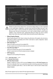
... (Note) Allows you to alter the clock ratio for the installed CPU. Fine CPU Clock Ratio (Note) Allows you made is dependent on system configurations. BIOS Setup CPU Frequency Displays the current operating CPU frequency. ******** Clock Chip Control Standard Clock Control CPU Host Clock Control Enables or disables the control of...
... (Note) Allows you to alter the clock ratio for the installed CPU. Fine CPU Clock Ratio (Note) Allows you made is dependent on system configurations. BIOS Setup CPU Frequency Displays the current operating CPU frequency. ******** Clock Chip Control Standard Clock Control CPU Host Clock Control Enables or disables the control of...
Manual
Page 22
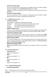
... 150 MHz. Options are : Auto (default), 4~11. Options are: Auto (default), Manual. >>>>> Standard Timing Control CAS Latency Time Options are : Auto (default), 200MHz, 266MHz, 333MHz. BIOS Setup - 22 - Important: It is enabled. Standard Lets the system operate at its basic performance level. (Default) Turbo Lets the system operate at system bootup...
... 150 MHz. Options are : Auto (default), 4~11. Options are: Auto (default), Manual. >>>>> Standard Timing Control CAS Latency Time Options are : Auto (default), 200MHz, 266MHz, 333MHz. BIOS Setup - 22 - Important: It is enabled. Standard Lets the system operate at its basic performance level. (Default) Turbo Lets the system operate at system bootup...
Manual
Page 23
...: General Help F7: Optimized Defaults Static tRead Value Options are : Auto (default), 1~15. tWR Options are : Auto (default), 1~31. tWTR Options are : Auto (default), 1~31. BIOS Setup
...: General Help F7: Optimized Defaults Static tRead Value Options are : Auto (default), 1~15. tWR Options are : Auto (default), 1~31. tWTR Options are : Auto (default), 1~31. BIOS Setup
Manual
Page 24
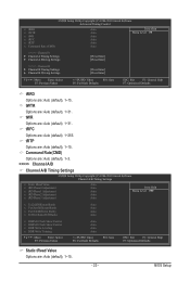
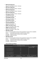
.... DDR Write Leveling Allows you to determine whether to fine-tune memory parameters to enhance memory compatibility. Auto Lets the BIOS decide whether to enable this function. (Default) Enabled Enables this function to enhance memory compatibility. Disabled Disables this function. Auto Lets ...Move Enter: Select F5: Previous Values +/-/PU/PD: Value F10: Save F6: Fail-Safe Defaults ESC: Exit F1: General Help F7: Optimized Defaults BIOS Setup - 24 - tRD Phase0 Adjustment Options are : Auto (default), +800ps~-700ps. Trd2wr(Same/Diff Rank) Options are : Auto (default), ...
.... DDR Write Leveling Allows you to determine whether to fine-tune memory parameters to enhance memory compatibility. Auto Lets the BIOS decide whether to enable this function. (Default) Enabled Enables this function to enhance memory compatibility. Disabled Disables this function. Auto Lets ...Move Enter: Select F5: Previous Values +/-/PU/PD: Value F10: Save F6: Fail-Safe Defaults ESC: Exit F1: General Help F7: Optimized Defaults BIOS Setup - 24 - tRD Phase0 Adjustment Options are : Auto (default), +800ps~-700ps. Trd2wr(Same/Diff Rank) Options are : Auto (default), ...
Manual
Page 25
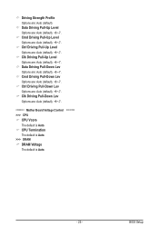
... Pull-Up Level Options are : Auto (default), +8~-7. Ctrl Driving Pull-Down Lev Options are : Auto (default), +8~-7. Ctrl Driving Pull-Up Level Options are : Auto (default). BIOS Setup Driving Strength Profile Options are : Auto (default), +8~-7. CPU Termination The default is Auto. >>> DRAM DRAM Voltage The default is Auto. Cmd Driving Pull-Down...
... Pull-Up Level Options are : Auto (default), +8~-7. Ctrl Driving Pull-Down Lev Options are : Auto (default), +8~-7. Ctrl Driving Pull-Up Level Options are : Auto (default). BIOS Setup Driving Strength Profile Options are : Auto (default), +8~-7. CPU Termination The default is Auto. >>> DRAM DRAM Voltage The default is Auto. Cmd Driving Pull-Down...
Manual
Page 26
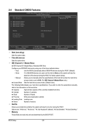
... Channel 0 Master/Slave only.) Access Mode Sets the hard drive access mode. (Default: Auto) The following fields display your IDE/SATA devices by the BIOS POST. Memory These fields are read-only and are : "All Errors," "No Errors," "All, But Keyboard" (default), "All, But Diskette," "All,... - Cylinder Number of the currently installed hard drive. Options are determined by using one of the three methods below: • Auto Lets the BIOS automatically detect IDE/SATA devices during the POST. (Default) • None If no IDE/SATA devices are used, set this item to None ...
... Channel 0 Master/Slave only.) Access Mode Sets the hard drive access mode. (Default: Auto) The following fields display your IDE/SATA devices by the BIOS POST. Memory These fields are read-only and are : "All Errors," "No Errors," "All, But Keyboard" (default), "All, But Diskette," "All,... - Cylinder Number of the currently installed hard drive. Options are determined by using one of the three methods below: • Auto Lets the BIOS automatically detect IDE/SATA devices during the POST. (Default) • None If no IDE/SATA devices are used, set this item to None ...

Manual
Page 27
...(C1E) (Note) C2/C2E State Support (Note) CPU Thermal Monitor 2(TM2) (Note) CPU EIST Function (Note) Virtualization Technology (Note) Delay For HDD (Secs) Backup BIOS Image to HDD [Press Enter] [Disabled] [Hard Disk] [CDROM] [Legacy LAN] [Setup] [Enabled] [Enabled] [Disabled] [Enabled] [Enabled] [Disabled] [Enabled... S.M.A.R.T. Capability CPU Multi-Threading (Note) Limit CPUID Max. Setup A password is only required for entering the BIOS Setup program. BIOS Setup Quick Boot Enables or disables the quick boot function to speed up the system boot-up process to shorten...
...(C1E) (Note) C2/C2E State Support (Note) CPU Thermal Monitor 2(TM2) (Note) CPU EIST Function (Note) Virtualization Technology (Note) Delay For HDD (Secs) Backup BIOS Image to HDD [Press Enter] [Disabled] [Hard Disk] [CDROM] [Legacy LAN] [Setup] [Enabled] [Enabled] [Disabled] [Enabled] [Enabled] [Disabled] [Enabled... S.M.A.R.T. Capability CPU Multi-Threading (Note) Limit CPUID Max. Setup A password is only required for entering the BIOS Setup program. BIOS Setup Quick Boot Enables or disables the quick boot function to speed up the system boot-up process to shorten...

Manual
Page 28
... (Default: Enabled) C2/C2E State Support (Note) Allows you to determine whether to let the CPU enter C2/C2E mode in system halt state. BIOS Setup - 28 - to 3 (Note) Allows you to determine whether to limit CPUID maximum value. This function may enhance protection for the computer, ... as the system boots up. For more information about Intel CPUs' unique features, please visit Intel's website. set a delay time for the BIOS to Enabled for Windows XP operating system; The adjustable range is from this feature. Depending on CPU loading, Intel EIST technology can function as ...
... (Default: Enabled) C2/C2E State Support (Note) Allows you to determine whether to let the CPU enter C2/C2E mode in system halt state. BIOS Setup - 28 - to 3 (Note) Allows you to determine whether to limit CPUID maximum value. This function may enhance protection for the computer, ... as the system boots up. For more information about Intel CPUs' unique features, please visit Intel's website. set a delay time for the BIOS to Enabled for Windows XP operating system; The adjustable range is from this feature. Depending on CPU loading, Intel EIST technology can function as ...

Manual
Page 29
.... The table below shows the supported features of the monitor display from the installed PCI graphics card, PCI Express graphics card or the onboard graphics. BIOS Setup 2-6 Advanced Chipset Features CMOS Setup Utility-Copyright (C) 1984-2010 Award Software Advanced Chipset Features ** VGA Setting ** Onboard VGA Init Display First PAVP Mode PAVP...
.... The table below shows the supported features of the monitor display from the installed PCI graphics card, PCI Express graphics card or the onboard graphics. BIOS Setup 2-6 Advanced Chipset Features CMOS Setup Utility-Copyright (C) 1984-2010 Award Software Advanced Chipset Features ** VGA Setting ** Onboard VGA Init Display First PAVP Mode PAVP...

Manual
Page 30
... the fault or short Onboard LAN Boot ROM Allows you wish to install a 3rd party add-in audio card instead of the attached LAN cable. BIOS Setup - 30 - Onboard H/W LAN Enables or disables the onboard LAN function. (Default: Enabled) If you to decide whether to Disabled. SMART LAN (LAN Cable Diagnostic...
... the fault or short Onboard LAN Boot ROM Allows you wish to install a 3rd party add-in audio card instead of the attached LAN cable. BIOS Setup - 30 - Onboard H/W LAN Enables or disables the onboard LAN function. (Default: Enabled) If you to decide whether to Disabled. SMART LAN (LAN Cable Diagnostic...
Manual
Page 31
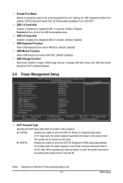
... F6: Fail-Safe Defaults ESC: Exit F1: General Help F7: Optimized Defaults ACPI Suspend Type Specifies the ACPI sleep state when the system enters suspend. BIOS Setup In S1 sleep state, the system appears suspended and stays in the S1 state. When signaled by Alarm [Disabled] x Date (of the USB functionalities...
... F6: Fail-Safe Defaults ESC: Exit F1: General Help F7: Optimized Defaults ACPI Suspend Type Specifies the ACPI sleep state when the system enters suspend. BIOS Setup In S1 sleep state, the system appears suspended and stays in the S1 state. When signaled by Alarm [Disabled] x Date (of the USB functionalities...


