Manual
Page 4
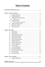
Table of Contents GA-G41MT-S2 Motherboard Layout 5 Chapter 1 Hardware Installation 6 1-1 Installation Precautions 6 1-2 Product Specifications 7 1-3 Installing the CPU and CPU Cooler 9 1-3-1 Installing the CPU...9 1-4 Installing the Memory 10 1-4-1 Dual Channel Memory Configuration 10 1-5 Installing an Expansion Card 10 1-6 Back Panel Connectors 11 1-7 Internal Connectors 12 Chapter 2 BIOS Setup 19 2-1 Startup Screen 19 2-2 The Main Menu 19 2-3 MB Intelligent Tweaker(M.I.T 20 2-4 Standard CMOS Features 26 2-5 Advanced BIOS Features 27 2-6 Advanced Chipset Features 29 2-7 ...
Table of Contents GA-G41MT-S2 Motherboard Layout 5 Chapter 1 Hardware Installation 6 1-1 Installation Precautions 6 1-2 Product Specifications 7 1-3 Installing the CPU and CPU Cooler 9 1-3-1 Installing the CPU...9 1-4 Installing the Memory 10 1-4-1 Dual Channel Memory Configuration 10 1-5 Installing an Expansion Card 10 1-6 Back Panel Connectors 11 1-7 Internal Connectors 12 Chapter 2 BIOS Setup 19 2-1 Startup Screen 19 2-2 The Main Menu 19 2-3 MB Intelligent Tweaker(M.I.T 20 2-4 Standard CMOS Features 26 2-5 Advanced BIOS Features 27 2-6 Advanced Chipset Features 29 2-7 ...
Manual
Page 5
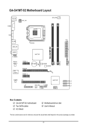
GA-G41MT-S2 Motherboard Layout KB_MS COMA ATX_12V VGA LGA775 CPU_FAN R_USB USB_LAN AUDIO F_AUDIO Atheros AR8151 iTE IT8718 Intel® G41 PCIEX1_1 PCIEX16 BATTERY PCIEX1_2 B_BIOS M_BIOS CODEC PCI LPT SYS_FAN F_USB2 F_USB1 Intel® ICH7 SATA2_0 CLR_CMOS GA-G41MT-S2 DDR3_1 DDR3_2 F_PANEL ATX SATA2_3 SATA2_2 SATA2_1 Box Contents GA-G41MT-S2 motherboard Two SATA cables I/O Shield Motherboard driver disk User's Manual The box contents above are for reference only and the actual items shall depend on the product package you obtain. - 5 -
GA-G41MT-S2 Motherboard Layout KB_MS COMA ATX_12V VGA LGA775 CPU_FAN R_USB USB_LAN AUDIO F_AUDIO Atheros AR8151 iTE IT8718 Intel® G41 PCIEX1_1 PCIEX16 BATTERY PCIEX1_2 B_BIOS M_BIOS CODEC PCI LPT SYS_FAN F_USB2 F_USB1 Intel® ICH7 SATA2_0 CLR_CMOS GA-G41MT-S2 DDR3_1 DDR3_2 F_PANEL ATX SATA2_3 SATA2_2 SATA2_1 Box Contents GA-G41MT-S2 motherboard Two SATA cables I/O Shield Motherboard driver disk User's Manual The box contents above are for reference only and the actual items shall depend on the product package you obtain. - 5 -
Manual
Page 7
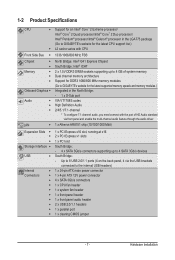
... connected to 4 SATA 3Gb/s devices USB South Bridge: - 1-2 Product Specifications CPU w w Support for the latest CPU support list.) L2 cache varies with CPU Front Side Bus w 1333/1066/800 MHz FSB Chipset w w Memory w w Onboard Graphics Audio LAN North Bridge: Intel® G41 Express Chipset South Bridge: Intel® ICH7 2 x 1.5V DDR3 DIMM sockets supporting up to the internal USB headers) Internal w 1 x 24-pin ATX main power connector...
... connected to 4 SATA 3Gb/s devices USB South Bridge: - 1-2 Product Specifications CPU w w Support for the latest CPU support list.) L2 cache varies with CPU Front Side Bus w 1333/1066/800 MHz FSB Chipset w w Memory w w Onboard Graphics Audio LAN North Bridge: Intel® G41 Express Chipset South Bridge: Intel® ICH7 2 x 1.5V DDR3 DIMM sockets supporting up to the internal USB headers) Internal w 1 x 24-pin ATX main power connector...
Manual
Page 10
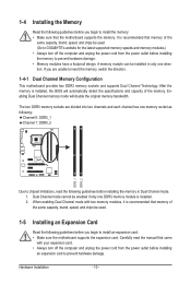
...motherboard supports the expansion card. After the memory is installed. 2. The two DDR3 memory sockets are unable to insert the memory, switch the direction. 1-4-1 Dual Channel Memory Configuration This motherboard provides two DDR3 memory sockets and supports Dual Channel Technology. Carefully read the following : Channel 0: DDR3_1 Channel 1: DDR3_2 DDR3_1 DDR3_2 Due to chipset limitations, read the manual that memory of the memory. Enabling Dual Channel memory mode will automatically detect the specifications and capacity of the same capacity, brand, speed, and chips be used...
...motherboard supports the expansion card. After the memory is installed. 2. The two DDR3 memory sockets are unable to insert the memory, switch the direction. 1-4-1 Dual Channel Memory Configuration This motherboard provides two DDR3 memory sockets and supports Dual Channel Technology. Carefully read the following : Channel 0: DDR3_1 Channel 1: DDR3_2 DDR3_1 DDR3_2 Due to chipset limitations, read the manual that memory of the memory. Enabling Dual Channel memory mode will automatically detect the specifications and capacity of the same capacity, brand, speed, and chips be used...
Manual
Page 11
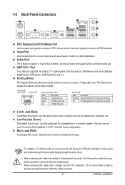
... out from the connector. Connect a monitor that supports D-Sub connection to connect front speakers in jack. Use this audio jack for USB devices such as a mouse, modem or other peripherals. Hardware Installation D-Sub Port The D-Sub port supports a 15-pin D-Sub connector. Use this jack. This jack can be connected to prevent an electrical short inside the cable connector. - 11 - Microphones must be used to this audio jack for a headphone or 2-channel speaker. Connection/ Speed LED Activity LED LAN Port Connection/Speed LED: State Description...
... out from the connector. Connect a monitor that supports D-Sub connection to connect front speakers in jack. Use this audio jack for USB devices such as a mouse, modem or other peripherals. Hardware Installation D-Sub Port The D-Sub port supports a 15-pin D-Sub connector. Use this jack. This jack can be connected to prevent an electrical short inside the cable connector. - 11 - Microphones must be used to this audio jack for a headphone or 2-channel speaker. Connection/ Speed LED Activity LED LAN Port Connection/Speed LED: State Description...
Manual
Page 14
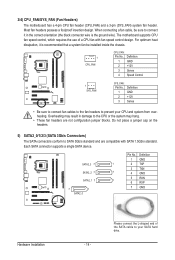
... a 3-pin (SYS_FAN) system fan header. When connecting a fan cable, be sure to connect it is the ground wire). Do not place a jumper cap on the headers. The motherboard supports CPU fan speed control, which requires the use of the SATA cable to prevent your SATA hard drive. SATA2_3 7 SATA2_2 7 SATA2_1 7 7 1 SATA2_0 Pin No. heating. Most fan headers possess a foolproof insertion design. Please connect the L-shaped end of a CPU fan with SATA 1.5Gb/s standard. Definition 1 GND 2 +12V 3 Sense DEBUG PORT DEBUG PORT...
... a 3-pin (SYS_FAN) system fan header. When connecting a fan cable, be sure to connect it is the ground wire). Do not place a jumper cap on the headers. The motherboard supports CPU fan speed control, which requires the use of the SATA cable to prevent your SATA hard drive. SATA2_3 7 SATA2_2 7 SATA2_1 7 7 1 SATA2_0 Pin No. heating. Most fan headers possess a foolproof insertion design. Please connect the L-shaped end of a CPU fan with SATA 1.5Gb/s standard. Definition 1 GND 2 +12V 3 Sense DEBUG PORT DEBUG PORT...
Manual
Page 16
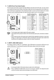
... wire assignments of the module connector match the pin assignments of the front and back panel audio connections simultane- You may connect your computer and unplug the power cord from the power outlet to prevent damage to work or even damage it. Incorrect connection between the module connector and the motherboard header will be sure to turn off your chassis front panel audio module to USB 2.0/1.1 specification. For purchasing the optional USB...
... wire assignments of the module connector match the pin assignments of the front and back panel audio connections simultane- You may connect your computer and unplug the power cord from the power outlet to prevent damage to work or even damage it. Incorrect connection between the module connector and the motherboard header will be sure to turn off your chassis front panel audio module to USB 2.0/1.1 specification. For purchasing the optional USB...

Manual
Page 17
... port via an optional LPT port cable. Open: Normal Short: Clear CMOS Values • Always turn off your computer, be sure to remove the jumper cap from the jumper. Failure to do so may cause damage to the motherboard. • After system restart, go to BIOS Setup to load factory defaults (select Load Optimized Defaults) or manually configure the BIOS settings (refer to touch the two pins for BIOS configurations). - 17 - Hardware Installation date information and BIOS configurations) and reset...
... port via an optional LPT port cable. Open: Normal Short: Clear CMOS Values • Always turn off your computer, be sure to remove the jumper cap from the jumper. Failure to do so may cause damage to the motherboard. • After system restart, go to BIOS Setup to load factory defaults (select Load Optimized Defaults) or manually configure the BIOS settings (refer to touch the two pins for BIOS configurations). - 17 - Hardware Installation date information and BIOS configurations) and reset...
Manual
Page 19
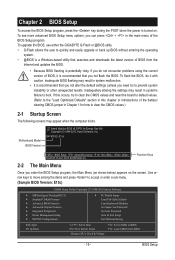
.../PCI Configurations PC Health Status Load Fail-Safe Defaults Load Optimized Defaults Set Supervisor Password Set User Password Save & Exit Setup Exit Without Saving ESC: Quit F8: Q-Flash Select Item F10: Save & Exit Setup Change CPU's Clock & Voltage F11: Save CMOS to BIOS F12: Load CMOS from the Internet and updates the BIOS. • Because BIOS flashing is potentially risky, if you do it is recommended that searches and downloads the latest version of the battery/ clearing CMOS jumper in the main menu of BIOS...
.../PCI Configurations PC Health Status Load Fail-Safe Defaults Load Optimized Defaults Set Supervisor Password Set User Password Save & Exit Setup Exit Without Saving ESC: Quit F8: Q-Flash Select Item F10: Save & Exit Setup Change CPU's Clock & Voltage F11: Save CMOS to BIOS F12: Load CMOS from the Internet and updates the BIOS. • Because BIOS flashing is potentially risky, if you do it is recommended that searches and downloads the latest version of the battery/ clearing CMOS jumper in the main menu of BIOS...
Manual
Page 21
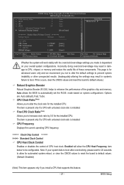
... Control CPU Host Clock Control Enables or disables the control of the graphics chip and memory. Enabled will work stably with unlocked clock ratio is installed. CPU Clock Ratio (Note) Allows you to boot. BIOS Setup Note: If your overall system configurations. CMOS Setup Utility-Copyright (C) 1984-2010 Award Software MB Intelligent Tweaker(M.I.T.) x CAS Latency Time 9 x tRCD 9 x tRP 9 x tRAS 24 >>>>> Advanced Timing Control } Advanced Timing Control Auto Auto Auto Auto [Press Enter] Item Help Menu Level ******** Mother Board Voltage...
... Control CPU Host Clock Control Enables or disables the control of the graphics chip and memory. Enabled will work stably with unlocked clock ratio is installed. CPU Clock Ratio (Note) Allows you to boot. BIOS Setup Note: If your overall system configurations. CMOS Setup Utility-Copyright (C) 1984-2010 Award Software MB Intelligent Tweaker(M.I.T.) x CAS Latency Time 9 x tRCD 9 x tRP 9 x tRAS 24 >>>>> Advanced Timing Control } Advanced Timing Control Auto Auto Auto Auto [Press Enter] Item Help Menu Level ******** Mother Board Voltage...
Manual
Page 22
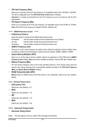
... : Auto (default), 1~63. >>>>> Advanced Timing Control Advanced Timing Control (Note) This item appears only if you install a CPU that supports this feature. Auto sets memory multiplier according to memory SPD data. (Default: Auto) Memory Frequency (Mhz) The first memory frequency value is enabled. the second is automatically adjusted according to the CPU Host Frequency (Mhz) and System Memory Multiplier settings. BIOS Setup - 22 - tRAS Options are : Auto (default), 200MHz, 266MHz, 333MHz. Auto sets the PCIe clock frequency to standard 100 MHz. (Default: Auto) ******** DRAM...
... : Auto (default), 1~63. >>>>> Advanced Timing Control Advanced Timing Control (Note) This item appears only if you install a CPU that supports this feature. Auto sets memory multiplier according to memory SPD data. (Default: Auto) Memory Frequency (Mhz) The first memory frequency value is enabled. the second is automatically adjusted according to the CPU Host Frequency (Mhz) and System Memory Multiplier settings. BIOS Setup - 22 - tRAS Options are : Auto (default), 200MHz, 266MHz, 333MHz. Auto sets the PCIe clock frequency to standard 100 MHz. (Default: Auto) ******** DRAM...
Manual
Page 24
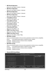
... enhance memory compatibility. tRD Phase0 Adjustment Options are : Auto (default), 1~15. Channel A/B Driving Settings CMOS Setup Utility-Copyright (C) 1984-2010 Award Software Channel A/B Driving Settings x Driving Strength Profile x Data Driving Pull-Up Level x Cmd Driving Pull-Up Level x Ctrl Driving Pull-Up Level x Clk Driving Pull-Up Level Auto Auto Auto Auto Auto Item Help Menu Level x Data Driving Pull-Down Lev x Cmd Driving Pull-Down Lev x Ctrl Driving Pull-Down Lev x Clk Driving Pull-Down Lev Auto Auto Auto Auto Move Enter...
... enhance memory compatibility. tRD Phase0 Adjustment Options are : Auto (default), 1~15. Channel A/B Driving Settings CMOS Setup Utility-Copyright (C) 1984-2010 Award Software Channel A/B Driving Settings x Driving Strength Profile x Data Driving Pull-Up Level x Cmd Driving Pull-Up Level x Ctrl Driving Pull-Up Level x Clk Driving Pull-Up Level Auto Auto Auto Auto Auto Item Help Menu Level x Data Driving Pull-Down Lev x Cmd Driving Pull-Down Lev x Ctrl Driving Pull-Down Lev x Clk Driving Pull-Down Lev Auto Auto Auto Auto Move Enter...

Manual
Page 27
... BIOS Setup program. Password Check Specifies whether a password is required every time the system boots, or only when you install a CPU that support multi-processor mode. Capability Enables or disables the S.M.A.R.T. (Self Monitoring and Reporting Technology) capability of the hard drive and to issue warnings when a third party hardware monitor utility is installed. (Default: Enabled) CPU Multi-Threading (Note) Allows you to determine whether to HDD [Press Enter] [Disabled] [Hard Disk] [CDROM] [Legacy LAN] [Setup] [Enabled] [Enabled] [Disabled] [Enabled] [Enabled] [Disabled] [Enabled...
... BIOS Setup program. Password Check Specifies whether a password is required every time the system boots, or only when you install a CPU that support multi-processor mode. Capability Enables or disables the S.M.A.R.T. (Self Monitoring and Reporting Technology) capability of the hard drive and to issue warnings when a third party hardware monitor utility is installed. (Default: Enabled) CPU Multi-Threading (Note) Allows you to determine whether to HDD [Press Enter] [Disabled] [Hard Disk] [CDROM] [Legacy LAN] [Setup] [Enabled] [Enabled] [Disabled] [Enabled] [Enabled] [Disabled] [Enabled...

Manual
Page 28
... Disable Bit function. Depending on CPU loading, Intel EIST technology can function as the system boots up. Set this item to Disabled for the BIOS to run multiple operating systems and applications in system halt state. Limit CPUID Max. The adjustable range is corrupted, it will allow a platform to initialize the hard drive as multiple virtual systems. (Default: Enabled) Delay For HDD (Secs) Allows you install a CPU that supports...
... Disable Bit function. Depending on CPU loading, Intel EIST technology can function as the system boots up. Set this item to Disabled for the BIOS to run multiple operating systems and applications in system halt state. Limit CPUID Max. The adjustable range is corrupted, it will allow a platform to initialize the hard drive as multiple virtual systems. (Default: Enabled) Delay For HDD (Secs) Allows you install a CPU that supports...

Manual
Page 29
...Sets the PCI Express graphics card as the first display. Enable this function if you wish to set up a dual view configuration, set this item to any user application. Blu-ray disc). Init Display First Specifies the first initiation of the PAVP Lite and Paranoid PAVP modes. PCI Sets the PCI graphics card as the first display. (Default) Onboard Sets the onboard graphics as the first display. BIOS Setup 2-6 Advanced Chipset Features CMOS Setup Utility-Copyright (C) 1984-2010 Award Software Advanced Chipset Features ** VGA Setting ** Onboard VGA Init Display...
...Sets the PCI Express graphics card as the first display. Enable this function if you wish to set up a dual view configuration, set this item to any user application. Blu-ray disc). Init Display First Specifies the first initiation of the PAVP Lite and Paranoid PAVP modes. PCI Sets the PCI graphics card as the first display. (Default) Onboard Sets the onboard graphics as the first display. BIOS Setup 2-6 Advanced Chipset Features CMOS Setup Utility-Copyright (C) 1984-2010 Award Software Advanced Chipset Features ** VGA Setting ** Onboard VGA Init Display...

Manual
Page 30
... CMOS Setup Utility-Copyright (C) 1984-2010 Award Software Integrated Peripherals Azalia Codec Onboard H/W LAN } SMART LAN Onboard LAN Boot ROM Onboard Serial Port 1 Onboard Parallel Port Parallel Port Mode USB 1.0 Controller USB 2.0 Controller USB Keyboard Support USB Mouse Support USB Storage Function [Auto] [Enabled] [Press Enter] [Disabled] [3F8/IRQ4] [378/IRQ7] [SPP] [Enabled] [Enabled] [Disabled] [Disabled] [Enabled] Item Help Menu Level Move Enter: Select F5: Previous Values +/-/PU/PD: Value F10: Save F6: Fail-Safe Defaults...
... CMOS Setup Utility-Copyright (C) 1984-2010 Award Software Integrated Peripherals Azalia Codec Onboard H/W LAN } SMART LAN Onboard LAN Boot ROM Onboard Serial Port 1 Onboard Parallel Port Parallel Port Mode USB 1.0 Controller USB 2.0 Controller USB Keyboard Support USB Mouse Support USB Storage Function [Auto] [Enabled] [Press Enter] [Disabled] [3F8/IRQ4] [378/IRQ7] [SPP] [Enabled] [Enabled] [Disabled] [Disabled] [Enabled] Item Help Menu Level Move Enter: Select F5: Previous Values +/-/PU/PD: Value F10: Save F6: Fail-Safe Defaults...
Manual
Page 31
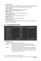
... sleep state, the system appears to enter the ACPI S1 (Power on Windows 7/Vista operating system only. - 31 - BIOS Setup The system can be used in MS-DOS. (Default: Disabled) USB Storage Function Determines whether to detect USB storage devices, including USB flash drives and USB hard drives during the POST. (Default: Enabled) 2-8 Power Management Setup CMOS Setup Utility-Copyright (C) 1984-2010 Award Software Power Management Setup Item Help ACPI Suspend Type [S3(STR)] Menu Level Soft-Off by PWR-BTTN [Instant-Off] PME Event Wake...
... sleep state, the system appears to enter the ACPI S1 (Power on Windows 7/Vista operating system only. - 31 - BIOS Setup The system can be used in MS-DOS. (Default: Disabled) USB Storage Function Determines whether to detect USB storage devices, including USB flash drives and USB hard drives during the POST. (Default: Enabled) 2-8 Power Management Setup CMOS Setup Utility-Copyright (C) 1984-2010 Award Software Power Management Setup Item Help ACPI Suspend Type [S3(STR)] Menu Level Soft-Off by PWR-BTTN [Instant-Off] PME Event Wake...
Manual
Page 32
... supports wake-up signal from a PCI or PCIe device. Note: To use this function, you to turn off the computer in a month. Note: When using the power button. Password Set a password with up event. (Default: Disabled) Note: To use this function, avoid inadequate shutdown from an ACPI sleep state by a wake-up function. (Default: Enabled) Resume by Alarm Determines whether to clear the password settings. (Note) Supported on automatically. Keyboard 98 Press POWER button on the Windows 98 keyboard to turn...
... supports wake-up signal from a PCI or PCIe device. Note: To use this function, you to turn off the computer in a month. Note: When using the power button. Password Set a password with up event. (Default: Disabled) Note: To use this function, avoid inadequate shutdown from an ACPI sleep state by a wake-up function. (Default: Enabled) Resume by Alarm Determines whether to clear the password settings. (Note) Supported on automatically. Keyboard 98 Press POWER button on the Windows 98 keyboard to turn...
Manual
Page 33
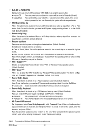
... Defaults PCI1 IRQ Assignment Auto 3,4,5,7,9,10,11,12,14,15 BIOS auto-assigns IRQ to the first PCI slot. (Default) Assigns IRQ 3,4,5,7,9,10,11,12,14,15 to the first PCI slot. 2-10 PC Health Status CMOS Setup Utility-Copyright (C) 1984-2010 Award Software PC Health Status Reset Case Open Status Case Opened Vcore DDR15V +3.3V +12V Current CPU Temperature Current CPU FAN Speed Current SYSTEM FAN Speed CPU Warning Temperature CPU FAN Fail Warning SYSTEM FAN Fail Warning CPU Smart FAN Control [Disabled...
... Defaults PCI1 IRQ Assignment Auto 3,4,5,7,9,10,11,12,14,15 BIOS auto-assigns IRQ to the first PCI slot. (Default) Assigns IRQ 3,4,5,7,9,10,11,12,14,15 to the first PCI slot. 2-10 PC Health Status CMOS Setup Utility-Copyright (C) 1984-2010 Award Software PC Health Status Reset Case Open Status Case Opened Vcore DDR15V +3.3V +12V Current CPU Temperature Current CPU FAN Speed Current SYSTEM FAN Speed CPU Warning Temperature CPU FAN Fail Warning SYSTEM FAN Fail Warning CPU Smart FAN Control [Disabled...
Manual
Page 34
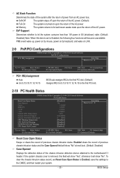
... system to load the safest BIOS default settings. If disabled, CPU fan runs at different speed according to load Fail-Safe defaults, which are : Disabled (default), 60oC/140oF, 70oC/158oF, 80oC/176oF, 90oC/194oF. CPU Warning Temperature Sets the warning threshold for the motherboard. BIOS Setup - 34 - You can adjust the fan speed with EasyTune based on this occurs. (Default: Disabled) CPU Smart FAN Control Enables or disables the CPU fan speed control function. Current Voltage(V) Vcore/DDR15V/+3.3V/+12V Displays the current system voltages. Options are...
... system to load the safest BIOS default settings. If disabled, CPU fan runs at different speed according to load Fail-Safe defaults, which are : Disabled (default), 60oC/140oF, 70oC/158oF, 80oC/176oF, 90oC/194oF. CPU Warning Temperature Sets the warning threshold for the motherboard. BIOS Setup - 34 - You can adjust the fan speed with EasyTune based on this occurs. (Default: Disabled) CPU Smart FAN Control Enables or disables the CPU fan speed control function. Current Voltage(V) Vcore/DDR15V/+3.3V/+12V Displays the current system voltages. Options are...


