
Manual
Page 3
...the specifications and features in this manual are legally registered to their respective owners. The trademarks mentioned in this product, GIGABYTE provides the following types of GIGABYTE. For example, "REV: 1.0" means the revision of the motherboard is the property of documentations: For ... or download the information on/from the Support&Downloads\Motherboard\Technology Guide page on your motherboard revision before updating motherboard BIOS, drivers, or when looking for technical information. Check your motherboard looks like this manual may be reproduced, copied,...
...the specifications and features in this manual are legally registered to their respective owners. The trademarks mentioned in this product, GIGABYTE provides the following types of GIGABYTE. For example, "REV: 1.0" means the revision of the motherboard is the property of documentations: For ... or download the information on/from the Support&Downloads\Motherboard\Technology Guide page on your motherboard revision before updating motherboard BIOS, drivers, or when looking for technical information. Check your motherboard looks like this manual may be reproduced, copied,...
Manual
Page 4
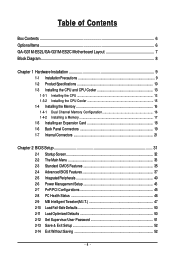
Table of Contents Box Contents ...6 OptionalItems...6 GA-G31M-ES2L/GA-G31M-ES2C Motherboard Layout 7 Block Diagram...8 Chapter 1 Hardware Installation 9 1-1 Installation Precautions 9 1-2 Product Specifications 10 1-3 Installing the CPU and CPU Cooler...Memory 17 1-5 Installing an Expansion Card 18 1-6 Back Panel Connectors 19 1-7 Internal Connectors 21 Chapter 2 BIOS Setup 31 2-1 Startup Screen 32 2-2 The Main Menu 33 2-3 Standard CMOS Features 35 2-4 Advanced BIOS Features 37 2-5 IntegratedPeripherals 40 2-6 Power Management Setup 43 2-7 PnP/PCI Configurations 45 2-8 PC Health ...
Table of Contents Box Contents ...6 OptionalItems...6 GA-G31M-ES2L/GA-G31M-ES2C Motherboard Layout 7 Block Diagram...8 Chapter 1 Hardware Installation 9 1-1 Installation Precautions 9 1-2 Product Specifications 10 1-3 Installing the CPU and CPU Cooler...Memory 17 1-5 Installing an Expansion Card 18 1-6 Back Panel Connectors 19 1-7 Internal Connectors 21 Chapter 2 BIOS Setup 31 2-1 Startup Screen 32 2-2 The Main Menu 33 2-3 Standard CMOS Features 35 2-4 Advanced BIOS Features 37 2-5 IntegratedPeripherals 40 2-6 Power Management Setup 43 2-7 PnP/PCI Configurations 45 2-8 PC Health ...
Manual
Page 5
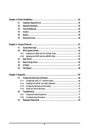
... 54 3-3 Technical Manuals 54 3-4 Contact ...55 3-5 System ...55 3-6 Download Center 56 Chapter 4 Unique Features 57 4-1 Xpress Recovery2 57 4-2 BIOS Update Utilities 60 4-2-1 Updating the BIOS with the Q-Flash Utility 60 4-2-2 Updating the BIOS with the @BIOS Utility 63 4-3 EasyTune 6 ...64 4-4 Easy Energy Saver 65 4-5 Q-Share ...67 4-6 Time Repair ...68 Chapter 5 Appendix ...69 5-1 Configuring Audio...
... 54 3-3 Technical Manuals 54 3-4 Contact ...55 3-5 System ...55 3-6 Download Center 56 Chapter 4 Unique Features 57 4-1 Xpress Recovery2 57 4-2 BIOS Update Utilities 60 4-2-1 Updating the BIOS with the Q-Flash Utility 60 4-2-2 Updating the BIOS with the @BIOS Utility 63 4-3 EasyTune 6 ...64 4-4 Easy Energy Saver 65 4-5 Q-Share ...67 4-6 Time Repair ...68 Chapter 5 Appendix ...69 5-1 Configuring Audio...
Manual
Page 8
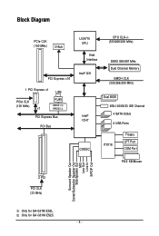
Only for GA-G31M-ES2L. Block Diagram PCIe CLK (100 MHz) D-Sub PCI Express x16 1 PCI Express x1 LAN PCIe CLK (100 MHz) x1 RJ45 AR8131 AR8132 PCI Express .../200 MHz) Intel® ICH7 CODEC Dual BIOS ATA-100/66/33 IDE Channel 4 SATA 3Gb/s 8 USB Ports IT8718 Floppy LPT Port COM Port PS/2 KB/Mouse 2 PCI PCI CLK (33 MHz) Surround Speaker Out Center/Subwoofer Speaker Out Side Speaker Out MIC Line Out Line In S/PDIF Out Only for GA-G31M-ES2C. - 8 -
Only for GA-G31M-ES2L. Block Diagram PCIe CLK (100 MHz) D-Sub PCI Express x16 1 PCI Express x1 LAN PCIe CLK (100 MHz) x1 RJ45 AR8131 AR8132 PCI Express .../200 MHz) Intel® ICH7 CODEC Dual BIOS ATA-100/66/33 IDE Channel 4 SATA 3Gb/s 8 USB Ports IT8718 Floppy LPT Port COM Port PS/2 KB/Mouse 2 PCI PCI CLK (33 MHz) Surround Speaker Out Center/Subwoofer Speaker Out Side Speaker Out MIC Line Out Line In S/PDIF Out Only for GA-G31M-ES2C. - 8 -
Manual
Page 11
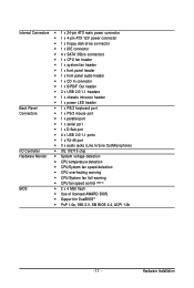
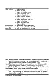
...; CPU temperature detection CPU/System fan speed detection CPU overheating warning CPU/System fan fail warning CPU fan speed control (Note 3) BIOS 2 x 4 Mbit flash Use of licensed AWARD BIOS Support for DualBIOSTM PnP 1.0a, DMI 2.0, SM...
...; CPU temperature detection CPU/System fan speed detection CPU overheating warning CPU/System fan fail warning CPU fan speed control (Note 3) BIOS 2 x 4 Mbit flash Use of licensed AWARD BIOS Support for DualBIOSTM PnP 1.0a, DMI 2.0, SM...
Manual
Page 12
Unique Features Bundled Software Operating System Form Factor Support for @BIOS Support for Q-Flash Support for Xpress BIOS Rescue Support for Download Center Support for Xpress Install Support for Xpress Recovery2 Support for ...Extreme/ CoreTM 2 Quad/ CoreTM 2 Duo/ Pentium Dual-Core/ Celeron Dual-Core/ Celeron 400 Series CPU to enable support for Easy Energy Saver. GA-G31M-ES2L/ES2C Motherboard - 12 - For example, 4 GB of HD Audio standard via front panel and enable the multi-channel audio feature through the audio driver...
Unique Features Bundled Software Operating System Form Factor Support for @BIOS Support for Q-Flash Support for Xpress BIOS Rescue Support for Download Center Support for Xpress Install Support for Xpress Recovery2 Support for ...Extreme/ CoreTM 2 Quad/ CoreTM 2 Duo/ Pentium Dual-Core/ Celeron Dual-Core/ Celeron 400 Series CPU to enable support for Easy Energy Saver. GA-G31M-ES2L/ES2C Motherboard - 12 - For example, 4 GB of HD Audio standard via front panel and enable the multi-channel audio feature through the audio driver...
Manual
Page 16
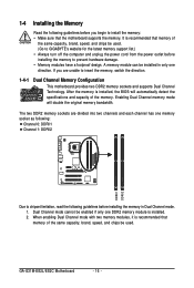
It is installed, the BIOS will double the original memory bandwidth. Enabling Dual Channel memory mode will automatically detect the specifications and capacity of the memory. After the memory is ... GIGABYTE's website for the latest memory support list.) • Always turn off the computer and unplug the power cord from the power outlet before installing the memory to insert the memory, switch the direction. 1-4-1 Dual Channel Memory Configuration This motherboard provides two DDR2 memory sockets and supports Dual Channel Technology. GA-G31M-ES2L/ES2C...
It is installed, the BIOS will double the original memory bandwidth. Enabling Dual Channel memory mode will automatically detect the specifications and capacity of the memory. After the memory is ... GIGABYTE's website for the latest memory support list.) • Always turn off the computer and unplug the power cord from the power outlet before installing the memory to insert the memory, switch the direction. 1-4-1 Dual Channel Memory Configuration This motherboard provides two DDR2 memory sockets and supports Dual Channel Technology. GA-G31M-ES2L/ES2C...
Manual
Page 18
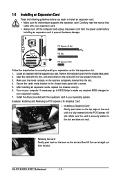
... the slot. 3. If necessary, go to BIOS Setup to make any required BIOS changes for your computer. Example: Installing and Removing a PCI Express x16 Graphics Card: • Installing a Graphics Card: Gently push down on the card are completely inserted into the PCI Express x16 slot. GA-G31M-ES2L/ES2C Motherboard - 18 - 1-5 Installing an Expansion Card...
... the slot. 3. If necessary, go to BIOS Setup to make any required BIOS changes for your computer. Example: Installing and Removing a PCI Express x16 Graphics Card: • Installing a Graphics Card: Gently push down on the card are completely inserted into the PCI Express x16 slot. GA-G31M-ES2L/ES2C Motherboard - 18 - 1-5 Installing an Expansion Card...
Manual
Page 25
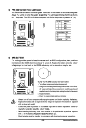
...+ 2 MPD- 1 3 MPD- System Status LED S0 On S1 Blinking S3/S4/S5 Off 9) BAT (BATTERY) The battery provides power to keep the values (such as BIOS configurations, date, and time information) in S1 sleep state. 8) PWR_LED (System Power LED Header) This header can be used to connect a system power LED on...
...+ 2 MPD- 1 3 MPD- System Status LED S0 On S1 Blinking S3/S4/S5 Off 9) BAT (BATTERY) The battery provides power to keep the values (such as BIOS configurations, date, and time information) in S1 sleep state. 8) PWR_LED (System Power LED Header) This header can be used to connect a system power LED on...
Manual
Page 26
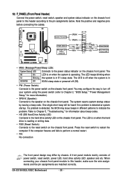
.... The LED is on when the hard drive is in S1 sleep state. When connecting your system using the power switch (refer to Chapter 2, "BIOS Setup," "Power Management Setup," for information about beep codes. • HD (IDE Hard Drive Activity LED) Connects to the reset switch on the...reading or writing data. • RES (Reset Switch): Connects to the hard drive activity LED on the chassis front panel. GA-G31M-ES2L/ES2C Motherboard - 26 - If a problem is detected, the BIOS may configure the way to turn off (S5). • PW (Power Switch): Connects to the speaker on when the ...
.... The LED is on when the hard drive is in S1 sleep state. When connecting your system using the power switch (refer to Chapter 2, "BIOS Setup," "Power Management Setup," for information about beep codes. • HD (IDE Hard Drive Activity LED) Connects to the reset switch on the...reading or writing data. • RES (Reset Switch): Connects to the hard drive activity LED on the chassis front panel. GA-G31M-ES2L/ES2C Motherboard - 26 - If a problem is detected, the BIOS may configure the way to turn off (S5). • PW (Power Switch): Connects to the speaker on when the ...
Manual
Page 29
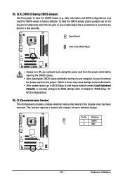
... the CMOS values and before turning on the two pins to temporarily short the two pins or use a metal object like a screwdriver to Chapter 2, "BIOS Setup," for a few seconds. Definition 1 Signal 1 2 GND - 29 - This function requires a chassis with chassis intrusion detection design. To clear the..., place a jumper cap on your computer and unplug the power cord from the jumper. Hardware Installation date information and BIOS configurations) and reset the CMOS values to clear the CMOS values (e.g. 15) CLR_CMOS (Clearing CMOS Jumper) Use this jumper to factory defaults...
... the CMOS values and before turning on the two pins to temporarily short the two pins or use a metal object like a screwdriver to Chapter 2, "BIOS Setup," for a few seconds. Definition 1 Signal 1 2 GND - 29 - This function requires a chassis with chassis intrusion detection design. To clear the..., place a jumper cap on your computer and unplug the power cord from the jumper. Hardware Installation date information and BIOS configurations) and reset the CMOS values to clear the CMOS values (e.g. 15) CLR_CMOS (Clearing CMOS Jumper) Use this jumper to factory defaults...
Manual
Page 31
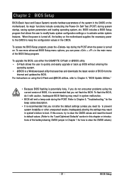
... board to default values. (Refer to the "Load Optimized Defaults" section in system's failure to clear the CMOS values.) - 31 - BIOS Setup To upgrade the BIOS, use either the GIGABYTE Q-Flash or @BIOS utility. • Q-Flash allows the user to prevent system instability or other unexpected results. Refer to Chapter 5, "Troubleshooting," for how to...
... board to default values. (Refer to the "Load Optimized Defaults" section in system's failure to clear the CMOS values.) - 31 - BIOS Setup To upgrade the BIOS, use either the GIGABYTE Q-Flash or @BIOS utility. • Q-Flash allows the user to prevent system instability or other unexpected results. Refer to Chapter 5, "Troubleshooting," for how to...
Manual
Page 32
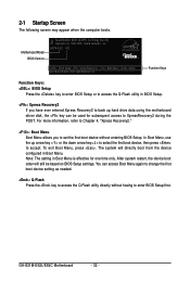
...: Q-Flash Press the key to access the Q-Flash utility directly without entering BIOS Setup. You can be based on BIOS Setup settings. The system will still be used for one time only. GA-G31M-ES2L/ES2C Motherboard - 32 - Note: The setting in Boot Menu is effective for subsequent... access to XpressRecovery2 during the POST. Motherboard Model BIOS Version Award Modular BIOS v6.00PG, An Energy Star Ally Copyright (C) 1984-2009,...
...: Q-Flash Press the key to access the Q-Flash utility directly without entering BIOS Setup. You can be based on BIOS Setup settings. The system will still be used for one time only. GA-G31M-ES2L/ES2C Motherboard - 32 - Note: The setting in Boot Menu is effective for subsequent... access to XpressRecovery2 during the POST. Motherboard Model BIOS Version Award Modular BIOS v6.00PG, An Energy Star Ally Copyright (C) 1984-2009,...
Manual
Page 33
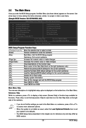
...move among the items and press to accept or enter a sub-menu. (Sample BIOS Version: GA-G31M-ES2L A02) CMOS Setup Utility-Copyright (C) 1984-2009 Award Software Standard CMOS Features Advanced BIOS Features Integrated Peripherals Power Management Setup PnP/PCI Configurations ...Access the Q-Flash utility Display system information Save all the changes and exit the BIOS Setup program Save CMOS to display a help screen. Press to BIOS F12: Load CMOS from BIOS Main Menu Help The onscreen description of a highlighted setup option is in the...
...move among the items and press to accept or enter a sub-menu. (Sample BIOS Version: GA-G31M-ES2L A02) CMOS Setup Utility-Copyright (C) 1984-2009 Award Software Standard CMOS Features Advanced BIOS Features Integrated Peripherals Power Management Setup PnP/PCI Configurations ...Access the Q-Flash utility Display system information Save all the changes and exit the BIOS Setup program Save CMOS to display a help screen. Press to BIOS F12: Load CMOS from BIOS Main Menu Help The onscreen description of a highlighted setup option is in the...
Manual
Page 34
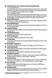
...and date, hard drive types, floppy disk drive types, and the type of errors that stop the system boot, etc. Advanced BIOS Features Use this menu to configure the device boot order, advanced features available on the CPU, and the primary display adapter. ...BIOS settings but not to a profile. A supervisor password allows you to save the current BIOS settings to make changes. Save & Exit Setup Save all changes and the previous settings remain in BIOS Setup. Set User Password Change, set , or disable password. You can use this task.) GA-G31M-ES2L/ES2C...
...and date, hard drive types, floppy disk drive types, and the type of errors that stop the system boot, etc. Advanced BIOS Features Use this menu to configure the device boot order, advanced features available on the CPU, and the primary display adapter. ...BIOS settings but not to a profile. A supervisor password allows you to save the current BIOS settings to make changes. Save & Exit Setup Save all changes and the previous settings remain in BIOS Setup. Set User Password Change, set , or disable password. You can use this task.) GA-G31M-ES2L/ES2C...

Manual
Page 35
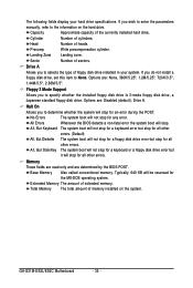
...LBA, Large. The date format is set to manually enter the specifications of the two methods below : • Auto • None • Manual Lets BIOS automatically detect IDE/SATA devices during the POST. (Default) If no IDE/SATA devices are used , set the date. Time Sets the system time. Access... Mode Sets the hard drive access mode. BIOS Setup Extended IDE Drive Configure your IDE/SATA devices by using one of the hard drive when the hard drive access mode is week (read...
...LBA, Large. The date format is set to manually enter the specifications of the two methods below : • Auto • None • Manual Lets BIOS automatically detect IDE/SATA devices during the POST. (Default) If no IDE/SATA devices are used , set the date. Time Sets the system time. Access... Mode Sets the hard drive access mode. BIOS Setup Extended IDE Drive Configure your IDE/SATA devices by using one of the hard drive when the hard drive access mode is week (read...
Manual
Page 36
...any error. Options are determined by the BIOS POST. All, But Disk/Key The system boot will not stop for a keyboard or a floppy disk drive error but stop for all other errors. Base Memory Also called conventional memory. GA-G31M-ES2L/ES2C Motherboard - 36 - Extended Memory The ...amount of heads. Sector Number of the currently installed hard drive. All Errors Whenever the BIOS detects a non-fatal error the system boot will be reserved for...
...any error. Options are determined by the BIOS POST. All, But Disk/Key The system boot will not stop for a keyboard or a floppy disk drive error but stop for all other errors. Base Memory Also called conventional memory. GA-G31M-ES2L/ES2C Motherboard - 36 - Extended Memory The ...amount of heads. Sector Number of the currently installed hard drive. All Errors Whenever the BIOS detects a non-fatal error the system boot will be reserved for...
Manual
Page 37
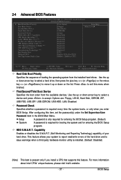
...F6: Fail-Safe Defaults ESC: Exit F1: General Help F7: Optimized Defaults Hard Disk Boot Priority Specifies the sequence of your hard drive. BIOS Setup to issue warnings when a third party hardware monitor utility is installed. (Default: Disabled) (Note) This item is required for booting ...the available devices. HDD S.M.A.R.T. Capability CPU Multi-Threading (Note) Limit CPUID Max. Setup System A password is only required for entering the BIOS Setup program. First/Second/Third Boot Device Specifies the boot order from the installed hard drives. Use the up or down arrow key ...
...F6: Fail-Safe Defaults ESC: Exit F1: General Help F7: Optimized Defaults Hard Disk Boot Priority Specifies the sequence of your hard drive. BIOS Setup to issue warnings when a third party hardware monitor utility is installed. (Default: Disabled) (Note) This item is required for booting ...the available devices. HDD S.M.A.R.T. Capability CPU Multi-Threading (Note) Limit CPUID Max. Setup System A password is only required for entering the BIOS Setup program. First/Second/Third Boot Device Specifies the boot order from the installed hard drives. Use the up or down arrow key ...

Manual
Page 39
... the onboard graphics controller. If you wish to Always Enable. Init Display First Specifies the first initiation of system memory allocated solely for GTT. - 39 - BIOS Setup Onboard VGA Enables or disables the onboard VGA function. PCI Sets the PCI graphics card as the first display. (Default) Onboard Sets the onboard...
... the onboard graphics controller. If you wish to Always Enable. Init Display First Specifies the first initiation of system memory allocated solely for GTT. - 39 - BIOS Setup Onboard VGA Enables or disables the onboard VGA function. PCI Sets the PCI graphics card as the first display. (Default) Onboard Sets the onboard...
Manual
Page 40
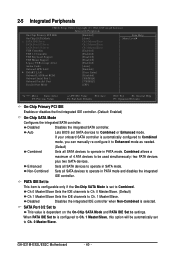
... Set to Combined. Auto Lets BIOS set to operate in PATA mode. Non-Combined Sets all SATA devices to Ch. 0 Master/Slave. When PATA IDE Set to is configured to operate in PATA mode and disables the integrated IDE controller. Disabled Disables the integrated SATA controller. GA-G31M-ES2L/ES2C Motherboard - 40 - If your...
... Set to Combined. Auto Lets BIOS set to operate in PATA mode. Non-Combined Sets all SATA devices to Ch. 0 Master/Slave. When PATA IDE Set to is configured to operate in PATA mode and disables the integrated IDE controller. Disabled Disables the integrated SATA controller. GA-G31M-ES2L/ES2C Motherboard - 40 - If your...


