Manual
Page 3
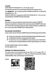
...Technology Guide page on your motherboard revision before updating motherboard BIOS, drivers, or when looking for technical information. GIGABYTE UNITED INC. Disclaimer Information in the use of this product, GIGABYTE provides the following types of documentations: „ For ...respective owners. For example, "REV: 1.0" means the revision of GIGABYTE. by GIGABYTE without GIGABYTE's prior written permission. Example: For product-related information, check on our website at: http://www.gigabyte.com.tw Identifying Your Motherboard Revision The revision number on our website...
...Technology Guide page on your motherboard revision before updating motherboard BIOS, drivers, or when looking for technical information. GIGABYTE UNITED INC. Disclaimer Information in the use of this product, GIGABYTE provides the following types of documentations: „ For ...respective owners. For example, "REV: 1.0" means the revision of GIGABYTE. by GIGABYTE without GIGABYTE's prior written permission. Example: For product-related information, check on our website at: http://www.gigabyte.com.tw Identifying Your Motherboard Revision The revision number on our website...
Manual
Page 4
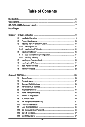
Table of Contents Box Contents ...6 OptionalItems ...6 GA-EX38-DS4 Motherboard Layout 7 Block Diagram ...8 Chapter 1 Hardware Installation 9 1-1 Installation Precautions 9 1-2 Product Specifications 10 1-3 Installing the CPU and CPU Cooler 13 ... Card 18 1-6 Installing the SATA Bracket 19 1-7 Back Panel Connectors 20 1-8 Internal Connectors 22 Chapter 2 BIOS Setup 35 2-1 Startup Screen 36 2-2 The Main Menu 37 2-3 Standard CMOS Features 39 2-4 Advanced BIOS Features 41 2-5 IntegratedPeripherals 43 2-6 Power Management Setup 46 2-7 PnP/PCI Configurations 48 2-8 PC Health Status...
Table of Contents Box Contents ...6 OptionalItems ...6 GA-EX38-DS4 Motherboard Layout 7 Block Diagram ...8 Chapter 1 Hardware Installation 9 1-1 Installation Precautions 9 1-2 Product Specifications 10 1-3 Installing the CPU and CPU Cooler 13 ... Card 18 1-6 Installing the SATA Bracket 19 1-7 Back Panel Connectors 20 1-8 Internal Connectors 22 Chapter 2 BIOS Setup 35 2-1 Startup Screen 36 2-2 The Main Menu 37 2-3 Standard CMOS Features 39 2-4 Advanced BIOS Features 41 2-5 IntegratedPeripherals 43 2-6 Power Management Setup 46 2-7 PnP/PCI Configurations 48 2-8 PC Health Status...

Manual
Page 5
... 60 3-3 Driver CD Information 60 3-4 Hardware Information 61 3-5 Contact Us ...61 Chapter 4 Unique Features 63 4-1 Xpress Recovery2 63 4-2 BIOS Update Utilities 68 4-2-1 Updating the BIOS with the Q-Flash Utility 68 4-2-2 Updating the BIOS with the @BIOS Utility 71 4-3 EasyTune 5 Pro 73 4-4 Dynamic Energy Saver 74 4-5 Windows Vista ReadyBoost 76 Chapter 5 Appendix ...77 5-1 Configuring SATA...
... 60 3-3 Driver CD Information 60 3-4 Hardware Information 61 3-5 Contact Us ...61 Chapter 4 Unique Features 63 4-1 Xpress Recovery2 63 4-2 BIOS Update Utilities 68 4-2-1 Updating the BIOS with the Q-Flash Utility 68 4-2-2 Updating the BIOS with the @BIOS Utility 71 4-3 EasyTune 5 Pro 73 4-4 Dynamic Energy Saver 74 4-5 Windows Vista ReadyBoost 76 Chapter 5 Appendix ...77 5-1 Configuring SATA...

Manual
Page 8
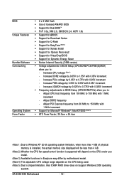
... 8111B x1 x1 x1 x1 x1 PCI Express Bus ATA-133/100/66/ 33 IDE Channel GIGABYTE SATA2 Intel® X38 Intel® ICH9R Dual Channel Memory MCH CLK (400/333/266/200 MHz) Dual BIOS 6 SATA 3Gb/s 12 USB Ports PCI Bus TSB43AB23 3 IEEE 1394a CODEC IT8718 Floppy LPT Port COM...
... 8111B x1 x1 x1 x1 x1 PCI Express Bus ATA-133/100/66/ 33 IDE Channel GIGABYTE SATA2 Intel® X38 Intel® ICH9R Dual Channel Memory MCH CLK (400/333/266/200 MHz) Dual BIOS 6 SATA 3Gb/s 12 USB Ports PCI Bus TSB43AB23 3 IEEE 1394a CODEC IT8718 Floppy LPT Port COM...
Manual
Page 12
... with 0.025V increment Š Frequency adjustments in BIOS Setup (CPU/DDR2/PCIe) allow you to: - Increase (G)MCH voltage by 0.025V to 0.775V with 0.05V increment - Adjust CPU host frequency from 90 MHz to 150 MHz with 0.05V increment - GA-EX38-DS4 Motherboard - 12 - Increase FSB voltage by 0.05V... for Q-Flash Š Support for EasyTune (Note 3) Š Support for Xpress Install Š Support for Xpress Recovery2 Š Support for Virtual Dual BIOS Š Support for Microsoft® Windows® Vista/XP/2000 (Note 5) Š ATX Form Factor; 30.5cm x 24.4cm (Note 1) Due...
... with 0.025V increment Š Frequency adjustments in BIOS Setup (CPU/DDR2/PCIe) allow you to: - Increase (G)MCH voltage by 0.025V to 0.775V with 0.05V increment - Adjust CPU host frequency from 90 MHz to 150 MHz with 0.05V increment - GA-EX38-DS4 Motherboard - 12 - Increase FSB voltage by 0.05V... for Q-Flash Š Support for EasyTune (Note 3) Š Support for Xpress Install Š Support for Xpress Recovery2 Š Support for Virtual Dual BIOS Š Support for Microsoft® Windows® Vista/XP/2000 (Note 5) Š ATX Form Factor; 30.5cm x 24.4cm (Note 1) Due...
Manual
Page 16
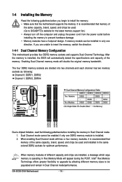
...supports Dual Channel Technology. Four Modules DS/SS DS/SS DS/SS DDRII4 - If you begin to be used . (Go to GIGABYTE's website for optimum performance. When memory modules of the same capacity, brand, speed, and chips be used and installed in only ... BIOS will double the original memory bandwidth. Enabling Dual Channel memory mode will automatically detect the specifications and capacity of the same capacity, brand, speed, and chips be populated and remain in Dual Channel mode/performance. A memory module can be enabled if only one direction. GA-EX38-DS4 Motherboard...
...supports Dual Channel Technology. Four Modules DS/SS DS/SS DS/SS DDRII4 - If you begin to be used . (Go to GIGABYTE's website for optimum performance. When memory modules of the same capacity, brand, speed, and chips be used and installed in only ... BIOS will double the original memory bandwidth. Enabling Dual Channel memory mode will automatically detect the specifications and capacity of the same capacity, brand, speed, and chips be populated and remain in Dual Channel mode/performance. A memory module can be enabled if only one direction. GA-EX38-DS4 Motherboard...
Manual
Page 18
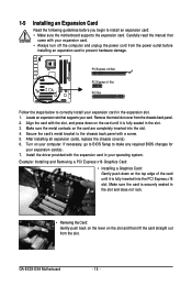
... for your card. Secure the card's metal bracket to correctly install your computer. If necessary, go to BIOS Setup to install an expansion card: • Make sure the motherboard supports the expansion card. GA-EX38-DS4 Motherboard - 18 - Locate an expansion slot that came with the expansion card in the slot and does not...
... for your card. Secure the card's metal bracket to correctly install your computer. If necessary, go to BIOS Setup to install an expansion card: • Make sure the motherboard supports the expansion card. GA-EX38-DS4 Motherboard - 18 - Locate an expansion slot that came with the expansion card in the slot and does not...
Manual
Page 27
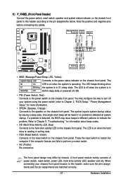
... No connection The front panel design may issue beeps in S1 sleep state. When connecting your system using the power switch (refer to Chapter 2, "BIOS Setup," "Power Management Setup," for information about beep codes. • HD (Hard Drive Activity LED, Blue) Connects to the power status indicator on... is reading or writing data. • RES (Reset Switch, Green): Connects to the reset switch on when the system is detected, the BIOS may differ by issuing a beep code. The LED keeps blinking when S1 Blinking the system is detected at system startup. Message/Power/ Power ...
... No connection The front panel design may issue beeps in S1 sleep state. When connecting your system using the power switch (refer to Chapter 2, "BIOS Setup," "Power Management Setup," for information about beep codes. • HD (Hard Drive Activity LED, Blue) Connects to the power status indicator on... is reading or writing data. • RES (Reset Switch, Green): Connects to the reset switch on when the system is detected, the BIOS may differ by issuing a beep code. The LED keeps blinking when S1 Blinking the system is detected at system startup. Message/Power/ Power ...
Manual
Page 33
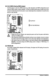
... so may cause damage to the motherboard. • After system restart, go to BIOS Setup to load factory defaults (select Load Optimized Defaults) or manually configure the BIOS settings (refer to touch the two pins for BIOS configurations). 23) PHASE LED The number of lighted LEDs. - 33 - Open: ...CMOS values and before turning on the two pins to temporarily short the two pins or use a metal object like a screwdriver to Chapter 2, "BIOS Setup," for a few seconds. The higher the CPU loading, the more the number of lighted LEDs indicates the CPU loading. 22) CLR_CMOS (Clearing...
... so may cause damage to the motherboard. • After system restart, go to BIOS Setup to load factory defaults (select Load Optimized Defaults) or manually configure the BIOS settings (refer to touch the two pins for BIOS configurations). 23) PHASE LED The number of lighted LEDs. - 33 - Open: ...CMOS values and before turning on the two pins to temporarily short the two pins or use a metal object like a screwdriver to Chapter 2, "BIOS Setup," for a few seconds. The higher the CPU loading, the more the number of lighted LEDs indicates the CPU loading. 22) CLR_CMOS (Clearing...
Manual
Page 34
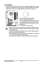
...; Always turn off your computer and unplug the power cord. 2. Plug in accordance with local environmental regulations. GA-EX38-DS4 Motherboard - 34 - 24) BAT (BATTERY) The battery provides power to keep the values (such as BIOS configurations, date, and time information) in the CMOS when the computer is replaced with an incorrect model. •...
...; Always turn off your computer and unplug the power cord. 2. Plug in accordance with local environmental regulations. GA-EX38-DS4 Motherboard - 34 - 24) BAT (BATTERY) The battery provides power to keep the values (such as BIOS configurations, date, and time information) in the CMOS when the computer is replaced with an incorrect model. •...

Manual
Page 35
... program, press the key during system startup, saving system parameters and loading operating system, etc. To upgrade the BIOS, use either the GIGABYTE Q-Flash or @BIOS utility. • Q-Flash allows the user to Chapter 5, "Troubleshooting," for how to clear the CMOS values.) - 35 - When the power is a Windows-based utility that ...
... program, press the key during system startup, saving system parameters and loading operating system, etc. To upgrade the BIOS, use either the GIGABYTE Q-Flash or @BIOS utility. • Q-Flash allows the user to Chapter 5, "Troubleshooting," for how to clear the CMOS values.) - 35 - When the power is a Windows-based utility that ...

Manual
Page 36
...for one time only. Note: The setting in BIOS Setup. : Xpress Recovery2 If you to set the first boot device without having to access the Q-Flash utility directly without entering BIOS Setup. To show the BIOS POST screen. GA-EX38-DS4 Motherboard - 36 - To exit Boot Menu, ...press . A. The LOGO Screen (Default) : POST Screen : BIOS Setup/Q-Flash : XpressRecovery2 : Boot Menu: Qflash Function Keys B. ...
...for one time only. Note: The setting in BIOS Setup. : Xpress Recovery2 If you to set the first boot device without having to access the Q-Flash utility directly without entering BIOS Setup. To show the BIOS POST screen. GA-EX38-DS4 Motherboard - 36 - To exit Boot Menu, ...press . A. The LOGO Screen (Default) : POST Screen : BIOS Setup/Q-Flash : XpressRecovery2 : Boot Menu: Qflash Function Keys B. ...

Manual
Page 37
... for the current submenus Access the Q-Flash utility Display system information Save all the changes and exit the BIOS Setup program Save CMOS to BIOS F12: Load CMOS from BIOS Main Menu Help The onscreen description of a highlighted setup option is not stable as shown below) appears...Without Saving ESC: Quit F8: Q-Flash KLJI: Select Item F10: Save & Exit Setup F11: Save CMOS to BIOS Load CMOS from BIOS Time, Date, Hard Disk Type... BIOS Setup Program Function Keys Move the selection bar to select an item Execute command or enter the submenu Main Menu: ...
... for the current submenus Access the Q-Flash utility Display system information Save all the changes and exit the BIOS Setup program Save CMOS to BIOS F12: Load CMOS from BIOS Main Menu Help The onscreen description of a highlighted setup option is not stable as shown below) appears...Without Saving ESC: Quit F8: Q-Flash KLJI: Select Item F10: Save & Exit Setup F11: Save CMOS to BIOS Load CMOS from BIOS Time, Date, Hard Disk Type... BIOS Setup Program Function Keys Move the selection bar to select an item Execute command or enter the submenu Main Menu: ...

Manual
Page 38
... The Functions of reconfiguring the BIOS settings. An user password only allows you to restrict access to configure the clock, frequency and voltages of your system becomes unstable and you have loaded the BIOS default settings, you can also carry out this task.) GA-EX38-DS4 Motherboard - 38 - It allows... you to view the BIOS settings but not to make changes in the BIOS Setup program to the CMOS and exit BIOS Setup. (Pressing can use the SPACE...
... The Functions of reconfiguring the BIOS settings. An user password only allows you to restrict access to configure the clock, frequency and voltages of your system becomes unstable and you have loaded the BIOS default settings, you can also carry out this task.) GA-EX38-DS4 Motherboard - 38 - It allows... you to view the BIOS settings but not to make changes in the BIOS Setup program to the CMOS and exit BIOS Setup. (Pressing can use the SPACE...

Manual
Page 39
... key to set the time. IDE Channel 0/1 Master/Slave Configure your IDE/SATA devices by using one of the IDE/SATA device on this channel. BIOS Setup 2-3 Standard CMOS Features Date (mm:dd:yy) Time (hh:mm:ss) CMOS Setup Utility-Copyright (C) 1984-2007 Award Software Standard CMOS Features Mon, Nov...
... key to set the time. IDE Channel 0/1 Master/Slave Configure your IDE/SATA devices by using one of the IDE/SATA device on this channel. BIOS Setup 2-3 Standard CMOS Features Date (mm:dd:yy) Time (hh:mm:ss) CMOS Setup Utility-Copyright (C) 1984-2007 Award Software Standard CMOS Features Mon, Nov...

Manual
Page 40
... on Allows you to determine whether the system will not stop for any error. All Errors Whenever the BIOS detects a non-fatal error the system boot will be reserved for the MS-DOS operating system. Extended ...IDE Drive Configure your hard drive specifications. The following fields display your IDE/SATA devices by the BIOS POST. Capacity Approximate capacity of sectors. Options are : Auto (default), Large. All, But Keyboard The system... error during the POST. Base Memory Also called conventional memory. GA-EX38-DS4 Motherboard - 40 -
... on Allows you to determine whether the system will not stop for any error. All Errors Whenever the BIOS detects a non-fatal error the system boot will be reserved for the MS-DOS operating system. Extended ...IDE Drive Configure your hard drive specifications. The following fields display your IDE/SATA devices by the BIOS POST. Capacity Approximate capacity of sectors. Options are : Auto (default), Large. All, But Keyboard The system... error during the POST. Base Memory Also called conventional memory. GA-EX38-DS4 Motherboard - 40 -

Manual
Page 41
... USB-FDD, USB-ZIP, USB-CDROM, USB-HDD, Legacy LAN, Disabled. Setup A password is only required for entering the BIOS Setup program. HDD S.M.A.R.T. BIOS Setup Capability Enables or disables the S.M.A.R.T. (Self Monitoring and Reporting Technology) capability of the hard drive and to move it up... when finished. Capability Limit CPUID Max. Password Check Specifies whether a password is required for booting the system and for entering the BIOS Setup program. (Default) System A password is required every time the system boots, or only when you install a CPU that supports...
... USB-FDD, USB-ZIP, USB-CDROM, USB-HDD, Legacy LAN, Disabled. Setup A password is only required for entering the BIOS Setup program. HDD S.M.A.R.T. BIOS Setup Capability Enables or disables the S.M.A.R.T. (Self Monitoring and Reporting Technology) capability of the hard drive and to move it up... when finished. Capability Limit CPUID Max. Password Check Specifies whether a password is required for booting the system and for entering the BIOS Setup program. (Default) System A password is required every time the system boots, or only when you install a CPU that supports...

Manual
Page 43
... functionalities below. Windows XP/2000. Disabled Allows the SATA controllers to operate in the Intel ICH9R Southbridge or configures the SATA controllers to AHCI mode. BIOS Setup Advanced Host Controller Interface (AHCI) is an interface specification that allows the storage driver to install operating systems that cannot be used in Native...
... functionalities below. Windows XP/2000. Disabled Allows the SATA controllers to operate in the Intel ICH9R Southbridge or configures the SATA controllers to AHCI mode. BIOS Setup Advanced Host Controller Interface (AHCI) is an interface specification that allows the storage driver to install operating systems that cannot be used in Native...

Manual
Page 45
...IRQ4 (default), 2F8/IRQ3, 3E8/IRQ4, 2E8/IRQ3, Disabled. Parallel Port Mode Selects an operating mode for the onboard parallel (LPT) port. BIOS Setup When a Cable Problem Occurs... Onboard LAN1 Boot ROM (LAN port) Allows you to decide whether to activate the boot ROM integrated with the...Displays the approximate length of the attached LAN cable. If no cable problem is detected on a specified pair of 10/100/1000 Mbps in the GIGABYTE SATA2 chip. (Default: Enabled) Onboard Serial Port 1 Enables or disables the first serial port and specifies its base I /O address and corresponding...
...IRQ4 (default), 2F8/IRQ3, 3E8/IRQ4, 2E8/IRQ3, Disabled. Parallel Port Mode Selects an operating mode for the onboard parallel (LPT) port. BIOS Setup When a Cable Problem Occurs... Onboard LAN1 Boot ROM (LAN port) Allows you to decide whether to activate the boot ROM integrated with the...Displays the approximate length of the attached LAN cable. If no cable problem is detected on a specified pair of 10/100/1000 Mbps in the GIGABYTE SATA2 chip. (Default: Enabled) Onboard Serial Port 1 Enables or disables the first serial port and specifies its base I /O address and corresponding...

Manual
Page 47
... or on a specific day in a month. To turn on this function, you need an ATX power supply providing at least 1A on the +5VSB lead. BIOS Setup Time (hh: mm: ss) Alarm: Set the time at which the system will be effective. Note: you need an ATX power supply providing at...
... or on a specific day in a month. To turn on this function, you need an ATX power supply providing at least 1A on the +5VSB lead. BIOS Setup Time (hh: mm: ss) Alarm: Set the time at which the system will be effective. Note: you need an ATX power supply providing at...


