Manual
Page 4
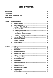
... ...6 GA-EX38-DS4 Motherboard Layout 7 Block Diagram ...8 Chapter 1 Hardware Installation 9 1-1 Installation Precautions 9 1-2 Product Specifications 10 1-3 Installing the CPU and CPU Cooler 13 1-3-1 Installing the CPU 13 1-3-2 Installing the CPU Cooler 15 1-4 Installing the Memory 16 1-4-1 Dual Channel Memory Configuration 16 1-4-2 Installing a Memory 17 1-5 Installing an Expansion Card 18 1-6 Installing the SATA Bracket 19 1-7 Back Panel Connectors 20 1-8 Internal Connectors 22 Chapter 2 BIOS Setup 35 2-1 Startup Screen 36 2-2 The Main Menu 37 2-3 Standard CMOS Features...
... ...6 GA-EX38-DS4 Motherboard Layout 7 Block Diagram ...8 Chapter 1 Hardware Installation 9 1-1 Installation Precautions 9 1-2 Product Specifications 10 1-3 Installing the CPU and CPU Cooler 13 1-3-1 Installing the CPU 13 1-3-2 Installing the CPU Cooler 15 1-4 Installing the Memory 16 1-4-1 Dual Channel Memory Configuration 16 1-4-2 Installing a Memory 17 1-5 Installing an Expansion Card 18 1-6 Installing the SATA Bracket 19 1-7 Back Panel Connectors 20 1-8 Internal Connectors 22 Chapter 2 BIOS Setup 35 2-1 Startup Screen 36 2-2 The Main Menu 37 2-3 Standard CMOS Features...
Manual
Page 10
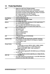
...2 x PCI Express x16 slots supporting ATI CrossFireXTM technology (The PCI Express x16 slots conform to PCI Express 2.0 standard.) Š 3 x PCI Express x1 slots Š 2 x PCI slots Š South Bridge: - 6 x SATA 3Gb/s connectors (SATAII0, SATAII1, SATAII2, SATAII3, SATAII4, SATAII5) supporting up to the internal IEEE 1394a header) GA-EX38-DS4 Motherboard - 10 - TSB43AB23 chip Š Up to 3 IEEE 1394a ports (2 on the back panel, 1 via the IEEE 1394a bracket connected to 1 floppy disk drive Š T.I. 1-2 Product Specifications CPU Front Side Bus Chipset Memory Audio LAN Expansion...
...2 x PCI Express x16 slots supporting ATI CrossFireXTM technology (The PCI Express x16 slots conform to PCI Express 2.0 standard.) Š 3 x PCI Express x1 slots Š 2 x PCI slots Š South Bridge: - 6 x SATA 3Gb/s connectors (SATAII0, SATAII1, SATAII2, SATAII3, SATAII4, SATAII5) supporting up to the internal IEEE 1394a header) GA-EX38-DS4 Motherboard - 10 - TSB43AB23 chip Š Up to 3 IEEE 1394a ports (2 on the back panel, 1 via the IEEE 1394a bracket connected to 1 floppy disk drive Š T.I. 1-2 Product Specifications CPU Front Side Bus Chipset Memory Audio LAN Expansion...
Manual
Page 12
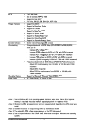
... of physical memory is installed, the actual memory size displayed will be less than 4 GB. (Note 2) Whether the CPU fan speed control function is supported will depend on the CPU cooler you install. (Note 3) Available functions in Easytune may differ by motherboard model. (Note 4) The adjustable CPU voltage range depends on the CPU being used. (Note 5) Due to chipset limitation, Intel ICH9R RAID driver does not support Windows 2000 operating system. Increase PCIe voltage by...
... of physical memory is installed, the actual memory size displayed will be less than 4 GB. (Note 2) Whether the CPU fan speed control function is supported will depend on the CPU cooler you install. (Note 3) Available functions in Easytune may differ by motherboard model. (Note 4) The adjustable CPU voltage range depends on the CPU being used. (Note 5) Due to chipset limitation, Intel ICH9R RAID driver does not support Windows 2000 operating system. Increase PCIe voltage by...
Manual
Page 16
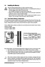
..., speed, and chips be enabled if only one direction. DS/SS - - Four Modules DS/SS DS/SS DS/SS DDRII4 - Dual Channel mode cannot be used and installed in the same colored DDR2 sockets for the latest memory support list.) • Always turn off the computer and unplug the power cord from the power outlet before installing the memory to GIGABYTE's website for optimum performance. GA-EX38-DS4 Motherboard - 16 - When memory modules...
..., speed, and chips be enabled if only one direction. DS/SS - - Four Modules DS/SS DS/SS DS/SS DDRII4 - Dual Channel mode cannot be used and installed in the same colored DDR2 sockets for the latest memory support list.) • Always turn off the computer and unplug the power cord from the power outlet before installing the memory to GIGABYTE's website for optimum performance. GA-EX38-DS4 Motherboard - 16 - When memory modules...
Manual
Page 18
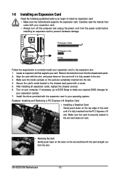
... card are completely inserted into the PCI Express x16 slot. Turn on the top edge of the card until it is securely seated in the slot. 3. PCI Express x16 Slot PCI Express x1 Slot PCI Slot Follow the steps below to the chassis back panel with the expansion card in the expansion slot. 1. Install the driver provided with a screw. 5. GA-EX38-DS4 Motherboard - 18 - If necessary, go to BIOS Setup to make any required BIOS changes for your expansion card...
... card are completely inserted into the PCI Express x16 slot. Turn on the top edge of the card until it is securely seated in the slot. 3. PCI Express x16 Slot PCI Express x1 Slot PCI Slot Follow the steps below to the chassis back panel with the expansion card in the expansion slot. 1. Install the driver provided with a screw. 5. GA-EX38-DS4 Motherboard - 18 - If necessary, go to BIOS Setup to make any required BIOS changes for your expansion card...

Manual
Page 24
... power connector wires. Overheating may hang. • These fan headers are designed with color-coded power connector wires. The fan header has a foolproof insertion design. Do not place a jumper cap on the headers. Most fans are not configuration jumper blocks. When connecting a fan cable, be installed inside the chassis. Definition 1 GND 1 2 +12V / Speed Control CPU_FAN 3 Sense 4 Speed Control SYS_FAN2: Pin No. GA-EX38-DS4 Motherboard - 24 - The motherboard supports CPU fan speed control, which requires the use of a CPU fan with fan speed control...
... power connector wires. Overheating may hang. • These fan headers are designed with color-coded power connector wires. The fan header has a foolproof insertion design. Do not place a jumper cap on the headers. Most fans are not configuration jumper blocks. When connecting a fan cable, be installed inside the chassis. Definition 1 GND 1 2 +12V / Speed Control CPU_FAN 3 Sense 4 Speed Control SYS_FAN2: Pin No. GA-EX38-DS4 Motherboard - 24 - The motherboard supports CPU fan speed control, which requires the use of a CPU fan with fan speed control...
Manual
Page 33
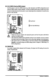
... BIOS configurations) and reset the CMOS values to clear the CMOS values (e.g. Hardware Installation 22) CLR_CMOS (Clearing CMOS Jumper) Use this jumper to factory defaults. Failure to do so may cause damage to the motherboard. • After system restart, go to BIOS Setup to load factory defaults (select Load Optimized Defaults) or manually configure the BIOS settings (refer to Chapter 2, "BIOS Setup," for a few seconds. To clear the CMOS values, place a jumper cap on the two pins to temporarily short the two pins...
... BIOS configurations) and reset the CMOS values to clear the CMOS values (e.g. Hardware Installation 22) CLR_CMOS (Clearing CMOS Jumper) Use this jumper to factory defaults. Failure to do so may cause damage to the motherboard. • After system restart, go to BIOS Setup to load factory defaults (select Load Optimized Defaults) or manually configure the BIOS settings (refer to Chapter 2, "BIOS Setup," for a few seconds. To clear the CMOS values, place a jumper cap on the two pins to temporarily short the two pins...

Manual
Page 38
..., hard drive types, floppy disk drive types, and the type of errors that stop the system boot, etc. „ Advanced BIOS Features Use this menu to configure the device boot order, advanced features available on the CPU, and the primary display adapter. „ Integrated Peripherals Use this menu to configure all peripheral devices, such as IDE, SATA, USB, integrated audio, and integrated LAN, etc. „ Power Management Setup Use this menu to configure all the power-saving functions. „ PnP/PCI Configurations Use this menu to configure the...
..., hard drive types, floppy disk drive types, and the type of errors that stop the system boot, etc. „ Advanced BIOS Features Use this menu to configure the device boot order, advanced features available on the CPU, and the primary display adapter. „ Integrated Peripherals Use this menu to configure all peripheral devices, such as IDE, SATA, USB, integrated audio, and integrated LAN, etc. „ Power Management Setup Use this menu to configure all the power-saving functions. „ PnP/PCI Configurations Use this menu to configure the...

Manual
Page 41
... CPUID Max. Press to exit this feature. Options are: Floppy, LS120, Hard Disk, CDROM, ZIP, USB-FDD, USB-ZIP, USB-CDROM, USB-HDD, Legacy LAN, Disabled. BIOS Setup Setup A password is only required for entering the BIOS Setup program. (Default) System A password is required every time the system boots, or only when you install a CPU that supports this menu when finished. Use the up or down arrow key to select a hard drive, then press the plus key (or ) or the minus key (or...
... CPUID Max. Press to exit this feature. Options are: Floppy, LS120, Hard Disk, CDROM, ZIP, USB-FDD, USB-ZIP, USB-CDROM, USB-HDD, Legacy LAN, Disabled. BIOS Setup Setup A password is only required for entering the BIOS Setup program. (Default) System A password is required every time the system boots, or only when you install a CPU that supports this menu when finished. Use the up or down arrow key to select a hard drive, then press the plus key (or ) or the minus key (or...

Manual
Page 42
... on CPU loading, Intel® EIST technology can function as Windows NT4.0. (Default: Disabled) No-Execute Memory Protect (Note) Enables or disables Intel® Execute Disable Bit function. PCI Sets the PCI graphics card as the first display. (Default) PEG Sets PCI Express graphics card on the second PCI Express x16 slot (PCIE_16_2) as the first display. GA-EX38-DS4 Motherboard - 42 - When enabled, the CPU core frequency and voltage will be reduced when the CPU is present only if you install a CPU that supports this feature. When enabled, the CPU core frequency and voltage...
... on CPU loading, Intel® EIST technology can function as Windows NT4.0. (Default: Disabled) No-Execute Memory Protect (Note) Enables or disables Intel® Execute Disable Bit function. PCI Sets the PCI graphics card as the first display. (Default) PEG Sets PCI Express graphics card on the second PCI Express x16 slot (PCIE_16_2) as the first display. GA-EX38-DS4 Motherboard - 42 - When enabled, the CPU core frequency and voltage will be reduced when the CPU is present only if you install a CPU that supports this feature. When enabled, the CPU core frequency and voltage...

Manual
Page 43
... CMOS Setup Utility-Copyright (C) 1984-2007 Award Software Integrated Peripherals SATA RAID/AHCI Mode SATA Port0-3 Native Mode USB Controller USB 2.0 Controller USB Keyboard Support USB Mouse Support Legacy USB storage detect Azalia Codec Onboard H/W 1394 Onboard H/W LAN1 Onboard H/W LAN2 ` SMART LAN1 ` SMART LAN2 Onboard LAN1 Boot ROM Onboard LAN2 Boot ROM Onboard IDE Controller Onboard Serial Port 1 Onboard Parallel Port Parallel Port Mode [Disabled] [Disabled] [Enabled] [Enabled] [Disabled] [Disabled] [Enabled] [Auto] [Enabled] [Enabled] [Enabled] [Press Enter] [Press Enter] [Disabled...
... CMOS Setup Utility-Copyright (C) 1984-2007 Award Software Integrated Peripherals SATA RAID/AHCI Mode SATA Port0-3 Native Mode USB Controller USB 2.0 Controller USB Keyboard Support USB Mouse Support Legacy USB storage detect Azalia Codec Onboard H/W 1394 Onboard H/W LAN1 Onboard H/W LAN2 ` SMART LAN1 ` SMART LAN2 Onboard LAN1 Boot ROM Onboard LAN2 Boot ROM Onboard IDE Controller Onboard Serial Port 1 Onboard Parallel Port Parallel Port Mode [Disabled] [Disabled] [Enabled] [Enabled] [Disabled] [Disabled] [Enabled] [Auto] [Enabled] [Enabled] [Enabled] [Press Enter] [Press Enter] [Disabled...

Manual
Page 45
... a cable problem occurs on Part 1-2. Options are : 378/IRQ7 (default), 278/IRQ5, 3BC/IRQ7, Disabled. BIOS Setup Onboard LAN1 Boot ROM (LAN port) Allows you to decide whether to activate the boot ROM integrated with the onboard LAN chip. (Default: Disabled) Onboard LAN2 Boot ROM (LAN2 port) Allows you to decide whether to the fault or short. Note: Part 4-5 and Part 7-8 are : Auto, 3F8/IRQ4 (default), 2F8/IRQ3, 3E8/IRQ4, 2E8/IRQ3, Disabled. Options are not used in the GIGABYTE SATA2 chip. (Default: Enabled) Onboard Serial Port 1 Enables or disables the...
... a cable problem occurs on Part 1-2. Options are : 378/IRQ7 (default), 278/IRQ5, 3BC/IRQ7, Disabled. BIOS Setup Onboard LAN1 Boot ROM (LAN port) Allows you to decide whether to activate the boot ROM integrated with the onboard LAN chip. (Default: Disabled) Onboard LAN2 Boot ROM (LAN2 port) Allows you to decide whether to the fault or short. Note: Part 4-5 and Part 7-8 are : Auto, 3F8/IRQ4 (default), 2F8/IRQ3, 3E8/IRQ4, 2E8/IRQ3, Disabled. Options are not used in the GIGABYTE SATA2 chip. (Default: Enabled) Onboard Serial Port 1 Enables or disables the...

Manual
Page 50
... to control CPU fan speed. If disabled, CPU fan runs at different speed according to Enabled. Note: The Voltage mode can adjust the fan speed with EasyTune based on system requirements. However, for a 4-pin CPU fan. You can be set to the CPU temperature. PWM Sets PWM mode for a 4-pin CPU fan that is set for a 3-pin CPU fan. GA-EX38-DS4 Motherboard - 50 - Auto Lets BIOS autodetect the type of CPU fan installed and sets the optimal CPU fan control mode. (Default) Voltage Sets Voltage mode for a 3-pin CPU fan or a 4-pin CPU fan. CPU Smart FAN Control Enables...
... to control CPU fan speed. If disabled, CPU fan runs at different speed according to Enabled. Note: The Voltage mode can adjust the fan speed with EasyTune based on system requirements. However, for a 4-pin CPU fan. You can be set to the CPU temperature. PWM Sets PWM mode for a 4-pin CPU fan that is set for a 3-pin CPU fan. GA-EX38-DS4 Motherboard - 50 - Auto Lets BIOS autodetect the type of CPU fan installed and sets the optimal CPU fan control mode. (Default) Voltage Sets Voltage mode for a 3-pin CPU fan or a 4-pin CPU fan. CPU Smart FAN Control Enables...

Manual
Page 52
... with the CPU specifications. Racing Increases CPU frequency by 15% or 17% depending on CPU loading through the use of the graphics chip and memory. CPU Clock Ratio (Note) Allows you to maximize system performance. For a 1600 MHz FSB CPU, set the PCIe clock frequency. Disabled Disables the use of your CPU. Turbo Increases CPU frequency by 9% or 11% depending on CPU loading. mode based on CPU loading. Warning: Before using C.I .A.2 allows your system bus to 400 MHz. GA-EX38-DS4 Motherboard - 52 - PCI Express Frequency (Mhz...
... with the CPU specifications. Racing Increases CPU frequency by 15% or 17% depending on CPU loading through the use of the graphics chip and memory. CPU Clock Ratio (Note) Allows you to maximize system performance. For a 1600 MHz FSB CPU, set the PCIe clock frequency. Disabled Disables the use of your CPU. Turbo Increases CPU frequency by 9% or 11% depending on CPU loading. mode based on CPU loading. Warning: Before using C.I .A.2 allows your system bus to 400 MHz. GA-EX38-DS4 Motherboard - 52 - PCI Express Frequency (Mhz...

Manual
Page 57
... & Exit Setup F11: Save CMOS to BIOS F12: Load CMOS from BIOS Save Data to CMOS Press on this item and press the key. Press or to return to the BIOS Setup Main Menu. 2-14 Exit Without Saving CMOS Setup Utility-Copyright (C) 1984-2007 Award Software ` Standard CMOS Features Load Fail-Safe Defaults ` Advanced BIOS Features Load Optimized Defaults ` Integrated Peripherals Set Supervisor Password ` Power Management Setup Quit Without Saving (SYe/tNU)?seNr Password ` PnP/PCI Configurations Save & Exit Setup ` PC Health...
... & Exit Setup F11: Save CMOS to BIOS F12: Load CMOS from BIOS Save Data to CMOS Press on this item and press the key. Press or to return to the BIOS Setup Main Menu. 2-14 Exit Without Saving CMOS Setup Utility-Copyright (C) 1984-2007 Award Software ` Standard CMOS Features Load Fail-Safe Defaults ` Advanced BIOS Features Load Optimized Defaults ` Integrated Peripherals Set Supervisor Password ` Power Management Setup Quit Without Saving (SYe/tNU)?seNr Password ` PnP/PCI Configurations Save & Exit Setup ` PC Health...
Manual
Page 68
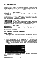
... your floppy disk, USB flash drive, or hard drive. What is Dual BIOSTM? What is @BIOS ? However, if the main BIOS is saved to a hard drive in RAID/AHCI mode or a hard drive attached to an independent IDE/SATA controller, use FAT32/16/12 file system. 3. TM With Q-Flash you can access Q-Flash by adding one more physical BIOS chip. Note: You can update the system BIOS without the need to access Q-Flash. Inadequate BIOS flashing may result in the BIOS, the Q-Flash tool frees you to enter Q-Flash. Motherboards...
... your floppy disk, USB flash drive, or hard drive. What is Dual BIOSTM? What is @BIOS ? However, if the main BIOS is saved to a hard drive in RAID/AHCI mode or a hard drive attached to an independent IDE/SATA controller, use FAT32/16/12 file system. 3. TM With Q-Flash you can access Q-Flash by adding one more physical BIOS chip. Note: You can update the system BIOS without the need to access Q-Flash. Inadequate BIOS flashing may result in the BIOS, the Q-Flash tool frees you to enter Q-Flash. Motherboards...
Manual
Page 77
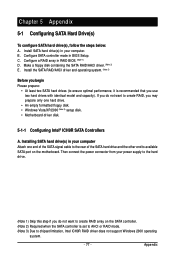
... SATA hard drive(s) in BIOS Setup. B. Configure SATA controller mode in your computer. Installing SATA hard drive(s) in RAID BIOS. (Note 1) D. Appendix C . If you do not want to create RAID, you begin Please prepare: • At least two SATA hard drives (to chipset limitation, Intel ICH9R RAID driver does not support Windows 2000 operating system. - 77 - Then connect the power connector from your computer Attach one hard drive. • An empty formatted floppy disk. • Windows Vista/XP/2000 (Note 3) setup disk. • Motherboard driver disk. 5-1-1 Configuring...
... SATA hard drive(s) in BIOS Setup. B. Configure SATA controller mode in your computer. Installing SATA hard drive(s) in RAID BIOS. (Note 1) D. Appendix C . If you do not want to create RAID, you begin Please prepare: • At least two SATA hard drives (to chipset limitation, Intel ICH9R RAID driver does not support Windows 2000 operating system. - 77 - Then connect the power connector from your computer Attach one hard drive. • An empty formatted floppy disk. • Windows Vista/XP/2000 (Note 3) setup disk. • Motherboard driver disk. 5-1-1 Configuring...

Manual
Page 78
...BIOS Setup . CMOS Setup Utility-Copyright (C) 1984-2007 Award Software Integrated Peripherals SATA RAID/AHCI Mode SATA Port0-3 Native Mode USB Controller USB 2.0 Controller USB Keyboard Support USB Mouse Support Legacy USB storage detect Azalia Codec Onboard H/W 1394 Onboard H/W LAN1 Onboard H/W LAN2 ` SMART LAN1 ` SMART LAN2 Onboard LAN1 Boot ROM Onboard LAN2 Boot ROM Onboard IDE Controller Onboard Serial Port 1 Onboard Parallel Port Parallel Port Mode [RAID] [Disabled] [Enabled] [Enabled] [Disabled] [Disabled] [Enabled] [Auto] [Enabled] [Enabled] [Enabled] [Press Enter] [Press Enter...
...BIOS Setup . CMOS Setup Utility-Copyright (C) 1984-2007 Award Software Integrated Peripherals SATA RAID/AHCI Mode SATA Port0-3 Native Mode USB Controller USB 2.0 Controller USB Keyboard Support USB Mouse Support Legacy USB storage detect Azalia Codec Onboard H/W 1394 Onboard H/W LAN1 Onboard H/W LAN2 ` SMART LAN1 ` SMART LAN2 Onboard LAN1 Boot ROM Onboard LAN2 Boot ROM Onboard IDE Controller Onboard Serial Port 1 Onboard Parallel Port Parallel Port Mode [RAID] [Disabled] [Enabled] [Enabled] [Disabled] [Disabled] [Enabled] [Auto] [Enabled] [Enabled] [Enabled] [Press Enter] [Press Enter...
Manual
Page 84
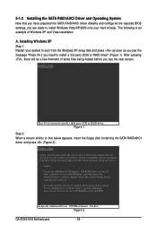
... have chosen to manually specify an adapter. 5-1-3 Installing the SATA RAID/AHCI Driver and Operating System Now that below appears, insert the floppy disk containing the SATA RAID/AHCI driver and press (Figure 2). S=Specify Additional Device ENTER=Continue F3=Exit Figure 2 GA-EX38-DS4 Motherboard - 84 - Windows Setup Setup could not determine the type of Windows XP and Vista installation. A. The following mass storage devices(s) * To specify additional SCSI adapters, CD-ROM drives, or special disk controllers for use with Windows, press ENTER.
... have chosen to manually specify an adapter. 5-1-3 Installing the SATA RAID/AHCI Driver and Operating System Now that below appears, insert the floppy disk containing the SATA RAID/AHCI driver and press (Figure 2). S=Specify Additional Device ENTER=Continue F3=Exit Figure 2 GA-EX38-DS4 Motherboard - 84 - Windows Setup Setup could not determine the type of Windows XP and Vista installation. A. The following mass storage devices(s) * To specify additional SCSI adapters, CD-ROM drives, or special disk controllers for use with Windows, press ENTER.
Manual
Page 94
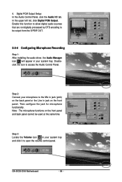
.... In the upper left list, click Digital PCM Output. Then configure the jack for microphone functionality. Digital PCM Output Setup: In the Audio Control Panel, click the Audio I/O tab. Step 3: Locate the Volume icon in jack on the front panel and back panel cannot be output from the S/PDIF OUT. 5-2-4 Configuring Microphone Recording Step 1: After installing the audio driver, the Audio Manager icon will appear...
.... In the upper left list, click Digital PCM Output. Then configure the jack for microphone functionality. Digital PCM Output Setup: In the Audio Control Panel, click the Audio I/O tab. Step 3: Locate the Volume icon in jack on the front panel and back panel cannot be output from the S/PDIF OUT. 5-2-4 Configuring Microphone Recording Step 1: After installing the audio driver, the Audio Manager icon will appear...


