Manual
Page 18
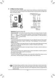
..., power LED, hard drive activity LED, speaker and etc. When connecting your system using the power switch (refer to Chapter 2, "BIOS Setup," "Power Management," for more information). •• Speaker (Speaker): Connects to the chassis intrusion switch/sensor on the chassis front ...panel. G.QBOFM 2 20 1 19 HD+ HD- 8) F_PANEL (Front Panel Header) Connect the power switch, reset switch, speaker, chassis intrusion switch/sensor and system status indicator on the chassis to this header, make sure the wire assignments and the pin assignments...
..., power LED, hard drive activity LED, speaker and etc. When connecting your system using the power switch (refer to Chapter 2, "BIOS Setup," "Power Management," for more information). •• Speaker (Speaker): Connects to the chassis intrusion switch/sensor on the chassis front ...panel. G.QBOFM 2 20 1 19 HD+ HD- 8) F_PANEL (Front Panel Header) Connect the power switch, reset switch, speaker, chassis intrusion switch/sensor and system status indicator on the chassis to this header, make sure the wire assignments and the pin assignments...
Manual
Page 22
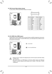
...Clear CMOS Jumper) Use this jumper to factory defaults. To clear the CMOS values, use a metal object like a screwdriver to Chapter 2, "BIOS Setup," for a few seconds. Open: Normal Short: Clear CMOS Values •• Always turn off your computer and unplug the power cord...•• After system restart, go to BIOS Setup to load factory defaults (select Load Optimized Defaults) or manually configure the BIOS settings (refer to touch the two pins for BIOS configurations). - 22 - date information and BIOS configurations) and reset the CMOS values to clear the CMOS values (e.g....
...Clear CMOS Jumper) Use this jumper to factory defaults. To clear the CMOS values, use a metal object like a screwdriver to Chapter 2, "BIOS Setup," for a few seconds. Open: Normal Short: Clear CMOS Values •• Always turn off your computer and unplug the power cord...•• After system restart, go to BIOS Setup to load factory defaults (select Load Optimized Defaults) or manually configure the BIOS settings (refer to touch the two pins for BIOS configurations). - 22 - date information and BIOS configurations) and reset the CMOS values to clear the CMOS values (e.g....

Manual
Page 23
... system instability or other unexpected results. To upgrade the BIOS, use either the GIGABYTE Q-Flash or @BIOS utility. •• Q-Flash allows the user to quickly and easily upgrade or back up BIOS without entering the operating system. •• @BIOS is a Windows-based utility that searches and downloads the.... •• It is recommended that you not alter the default settings (unless you not flash the BIOS. If this occurs, try to clear the CMOS values and reset the board to default values. (Refer to the "Load Optimized Defaults" section in this chapter or introductions ...
... system instability or other unexpected results. To upgrade the BIOS, use either the GIGABYTE Q-Flash or @BIOS utility. •• Q-Flash allows the user to quickly and easily upgrade or back up BIOS without entering the operating system. •• @BIOS is a Windows-based utility that searches and downloads the.... •• It is recommended that you not alter the default settings (unless you not flash the BIOS. If this occurs, try to clear the CMOS values and reset the board to default values. (Refer to the "Load Optimized Defaults" section in this chapter or introductions ...
Manual
Page 25
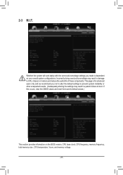
..., clear the CMOS values and reset the board to default values.) This section provides information on your overall system configurations. Incorrectly doing overclock/overvoltage may result in damage to boot. This page is for advanced users only and we recommend you made is dependent on the BIOS version, CPU base clock, CPU...
..., clear the CMOS values and reset the board to default values.) This section provides information on your overall system configurations. Incorrectly doing overclock/overvoltage may result in damage to boot. This page is for advanced users only and we recommend you made is dependent on the BIOS version, CPU base clock, CPU...
Manual
Page 29
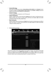
...and stability. When Extreme Memory Profile (X.M.P.) is set to Profile1 or Profile2, this item will display as 1.50V. Auto lets the BIOS automatically configure this item will display the value based on the SPD data on the XMP memory. && Profile VTT Voltage The value ...Default: Auto) `` Channel A/B Timing Settings This sub-menu provides memory timing settings for each channel of memory. Auto lets the BIOS automatically configure this occurs, please reset the board to default values by loading optimized defaults or clearing the CMOS values. - 29 - Note: Your system may become...
...and stability. When Extreme Memory Profile (X.M.P.) is set to Profile1 or Profile2, this item will display as 1.50V. Auto lets the BIOS automatically configure this item will display the value based on the SPD data on the XMP memory. && Profile VTT Voltage The value ...Default: Auto) `` Channel A/B Timing Settings This sub-menu provides memory timing settings for each channel of memory. Auto lets the BIOS automatically configure this occurs, please reset the board to default values by loading optimized defaults or clearing the CMOS values. - 29 - Note: Your system may become...


