Manual
Page 3
...Documentation Classifications In order to their respective owners. Check your motherboard looks like this product, GIGABYTE provides the following types of documentations: For quick set-up of GIGABYTE. Copyright © 2011 GIGA-BYTE TECHNOLOGY CO., LTD. For example, "REV: ... manual is protected by GIGABYTE without GIGABYTE's prior written permission. For product-related information, check on our website at: http://www.gigabyte.com Identifying Your Motherboard Revision The revision number on your motherboard revision before updating motherboard BIOS, drivers, or when ...
...Documentation Classifications In order to their respective owners. Check your motherboard looks like this product, GIGABYTE provides the following types of documentations: For quick set-up of GIGABYTE. Copyright © 2011 GIGA-BYTE TECHNOLOGY CO., LTD. For example, "REV: ... manual is protected by GIGABYTE without GIGABYTE's prior written permission. For product-related information, check on our website at: http://www.gigabyte.com Identifying Your Motherboard Revision The revision number on your motherboard revision before updating motherboard BIOS, drivers, or when ...
Manual
Page 4
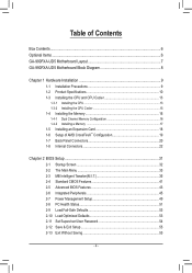
Table of Contents Box Contents...6 Optional Items...6 GA-990FXA-UD5 Motherboard Layout 7 GA-990FXA-UD5 Motherboard Block Diagram 8 Chapter 1 Hardware Installation 9 1-1 Installation Precautions 9 1-2 Product Specifications 10 1-3 Installing the CPU and CPU ...™ Configuration 19 1-7 Back Panel Connectors 20 1-8 Internal Connectors 22 Chapter 2 BIOS Setup 31 2-1 Startup Screen 32 2-2 The Main Menu 33 2-3 MB Intelligent Tweaker(M.I.T 35 2-4 Standard CMOS Features 41 2-5 Advanced BIOS Features 43 2-6 Integrated Peripherals 45 2-7 Power Management Setup 49 2-8 PC Health Status...
Table of Contents Box Contents...6 Optional Items...6 GA-990FXA-UD5 Motherboard Layout 7 GA-990FXA-UD5 Motherboard Block Diagram 8 Chapter 1 Hardware Installation 9 1-1 Installation Precautions 9 1-2 Product Specifications 10 1-3 Installing the CPU and CPU ...™ Configuration 19 1-7 Back Panel Connectors 20 1-8 Internal Connectors 22 Chapter 2 BIOS Setup 31 2-1 Startup Screen 32 2-2 The Main Menu 33 2-3 MB Intelligent Tweaker(M.I.T 35 2-4 Standard CMOS Features 41 2-5 Advanced BIOS Features 43 2-6 Integrated Peripherals 45 2-7 Power Management Setup 49 2-8 PC Health Status...
Manual
Page 5
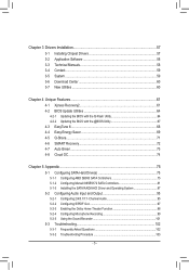
... 58 3-4 Contact...59 3-5 System...59 3-6 Download Center 60 3-7 New Utilities...60 Chapter 4 Unique Features 61 4-1 Xpress Recovery2 61 4-2 BIOS Update Utilities 64 4-2-1 Updating the BIOS with the Q-Flash Utility 64 4-2-2 Updating the BIOS with the @BIOS Utility 67 4-3 EasyTune 6...68 4-4 Easy Energy Saver 69 4-5 Q-Share...71 4-6 SMART Recovery 72 4-7 Auto Green...73 4-8 Cloud OC...
... 58 3-4 Contact...59 3-5 System...59 3-6 Download Center 60 3-7 New Utilities...60 Chapter 4 Unique Features 61 4-1 Xpress Recovery2 61 4-2 BIOS Update Utilities 64 4-2-1 Updating the BIOS with the Q-Flash Utility 64 4-2-2 Updating the BIOS with the @BIOS Utility 67 4-3 EasyTune 6...68 4-4 Easy Energy Saver 69 4-5 Q-Share...71 4-6 SMART Recovery 72 4-7 Auto Green...73 4-8 Cloud OC...
Manual
Page 6
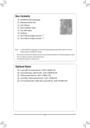
...go to GIGABYTE's website. • The box contents above are subject to change without notice. • The motherboard image is for reference only and the actual items shall depend on the product package you need SLI-supported graphics cards, BIOS, and ...driver. Optional Items 2-port USB 2.0 bracket (Part No. 12CR1-1UB030-5*R) 2-port SATA power cable (Part No. 12CF1-2SERPW-0*R) COM port cable (Part No. 12CF1-1CM001-3*R) 2-port IEEE 1394a bracket (Part No. 12CF1-1IE008-0*R) 3.5" Front Panel with 2 USB 3.0/2.0 ports (Part No. 12CR1-FPX582-0*R) - 6 - Box Contents GA-990FXA-UD5...
...go to GIGABYTE's website. • The box contents above are subject to change without notice. • The motherboard image is for reference only and the actual items shall depend on the product package you need SLI-supported graphics cards, BIOS, and ...driver. Optional Items 2-port USB 2.0 bracket (Part No. 12CR1-1UB030-5*R) 2-port SATA power cable (Part No. 12CF1-2SERPW-0*R) COM port cable (Part No. 12CF1-1CM001-3*R) 2-port IEEE 1394a bracket (Part No. 12CF1-1IE008-0*R) 3.5" Front Panel with 2 USB 3.0/2.0 ports (Part No. 12CR1-FPX582-0*R) - 6 - Box Contents GA-990FXA-UD5...
Manual
Page 8
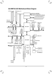
GA-990FXA-UD5 Motherboard Block Diagram 2 PCI Express x8 1 PCI Express x16 1 PCI Express x16 CPU CLK+/- (200 MHz) or DDR3 2000(O.C.)/1866/1600/1333/1066 MHz AM3+/... CLK (100 MHz) PCI Express Bus AMD SB950 14 USB 2.0/1.1 6 SATA 6Gb/s 1 PCI Express x1 2 SATA 6Gb/s 2 USB 3.0/2.0 PCI Bus VIA VT6308 2 IEEE 1394a Dual BIOS LPC Bus CODEC iTE IT8720 COM Port PS/2 KB/Mouse Surround Speaker Out Center/Subwoofer Speaker Out Side Speaker Out MIC Line Out Line In...
GA-990FXA-UD5 Motherboard Block Diagram 2 PCI Express x8 1 PCI Express x16 1 PCI Express x16 CPU CLK+/- (200 MHz) or DDR3 2000(O.C.)/1866/1600/1333/1066 MHz AM3+/... CLK (100 MHz) PCI Express Bus AMD SB950 14 USB 2.0/1.1 6 SATA 6Gb/s 1 PCI Express x1 2 SATA 6Gb/s 2 USB 3.0/2.0 PCI Bus VIA VT6308 2 IEEE 1394a Dual BIOS LPC Bus CODEC iTE IT8720 COM Port PS/2 KB/Mouse Surround Speaker Out Center/Subwoofer Speaker Out Side Speaker Out MIC Line Out Line In...
Manual
Page 12
...;Š 2 x 32 Mbit flash ŠŠ Use of licensed AWARD BIOS ŠŠ Support for DualBIOS™ ŠŠ PnP 1.0a, DMI 2.0, SM BIOS 2.4, ACPI 1.0b Unique Features ŠŠ Support for @BIOS ŠŠ Support for Q-Flash ŠŠ Support for Xpress BIOS Rescue ŠŠ Support for Download Center ŠŠ Support...
...;Š 2 x 32 Mbit flash ŠŠ Use of licensed AWARD BIOS ŠŠ Support for DualBIOS™ ŠŠ PnP 1.0a, DMI 2.0, SM BIOS 2.4, ACPI 1.0b Unique Features ŠŠ Support for @BIOS ŠŠ Support for Q-Flash ŠŠ Support for Xpress BIOS Rescue ŠŠ Support for Download Center ŠŠ Support...
Manual
Page 16
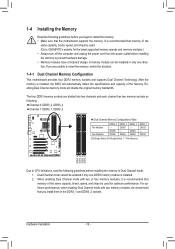
... memory. DS/SS DS/SS DDR3_2 DS/SS - Dual Channel mode cannot be installed in only one DDR3 memory module is installed, the BIOS will double the original memory bandwidth. 1-4 Installing the Memory Read the following guidelines before you begin to install the memory: • Make ... with two or four memory modules, it is recommended that memory of the same capacity, brand, speed, and chips be used . (Go to GIGABYTE's website for optimum performance. Hardware Installation - 16 - When enabling Dual Channel mode with two memory modules, we recommend that the motherboard supports the ...
... memory. DS/SS DS/SS DDR3_2 DS/SS - Dual Channel mode cannot be installed in only one DDR3 memory module is installed, the BIOS will double the original memory bandwidth. 1-4 Installing the Memory Read the following guidelines before you begin to install the memory: • Make ... with two or four memory modules, it is recommended that memory of the same capacity, brand, speed, and chips be used . (Go to GIGABYTE's website for optimum performance. Hardware Installation - 16 - When enabling Dual Channel mode with two memory modules, we recommend that the motherboard supports the ...
Manual
Page 18
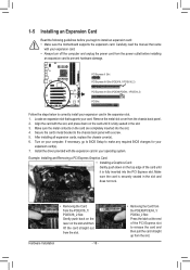
... card until it is fully seated in the expansion slot. 1. Make sure the metal contacts on your card. If necessary, go to BIOS Setup to make any required BIOS changes for your expansion card. • Always turn off the computer and unplug the power cord from the slot. Make sure the card...
... card until it is fully seated in the expansion slot. 1. Make sure the metal contacts on your card. If necessary, go to BIOS Setup to make any required BIOS changes for your expansion card. • Always turn off the computer and unplug the power cord from the slot. Make sure the card...
Manual
Page 24
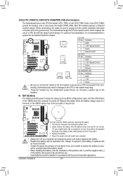
... minute. (Or use of a CPU fan with fan speed control design. Replace the battery when the battery voltage drops to keep the values (such as BIOS configurations, date, and time information) in damage to replace the battery by removing the battery: 111 Turn off your CPU and system from the battery...
... minute. (Or use of a CPU fan with fan speed control design. Replace the battery when the battery voltage drops to keep the values (such as BIOS configurations, date, and time information) in damage to replace the battery by removing the battery: 111 Turn off your CPU and system from the battery...
Manual
Page 26
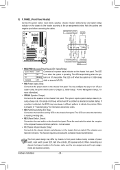
...LED Connects to the power switch on the chassis front panel. The system reports system startup status by chassis. If a problem is detected, the BIOS may differ by issuing a beep code. You may configure the way to turn off (S5). • PW (Power Switch, Red): Connects to...The LED S0 On is on the chassis to the pin assignments below. When connecting your system using the power switch (refer to Chapter 2, "BIOS Setup," "Power Management Setup," for information about beep codes. • HD (Hard Drive Activity LED, Blue) Connects to the hard drive activity ...
...LED Connects to the power switch on the chassis front panel. The system reports system startup status by chassis. If a problem is detected, the BIOS may differ by issuing a beep code. You may configure the way to turn off (S5). • PW (Power Switch, Red): Connects to...The LED S0 On is on the chassis to the pin assignments below. When connecting your system using the power switch (refer to Chapter 2, "BIOS Setup," "Power Management Setup," for information about beep codes. • HD (Hard Drive Activity LED, Blue) Connects to the hard drive activity ...
Manual
Page 28
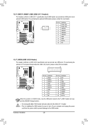
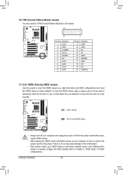
... ON/OFF Charge function. Pin No. Definition 1 VBUS 11 D2+ 2 SSRX1- 12 D2- 3 SSRX1+ 13 GND 4 GND 14 SSTX2+ 5 SSTX1- 15 SSTX2- 6 SSTX1+ 16 GND BIOS 7 GND 17 SSRX2+ DB_PORT 8 D1- 18 SSRX2- 9 D1+ 19 VBUS 10 NC 20 No Pin When the system is in S4/S5 mode, only the...
... ON/OFF Charge function. Pin No. Definition 1 VBUS 11 D2+ 2 SSRX1- 12 D2- 3 SSRX1+ 13 GND 4 GND 14 SSTX2+ 5 SSTX1- 15 SSTX2- 6 SSTX1+ 16 GND BIOS 7 GND 17 SSRX2+ DB_PORT 8 D1- 18 SSRX2- 9 D1+ 19 VBUS 10 NC 20 No Pin When the system is in S4/S5 mode, only the...
Manual
Page 30
... CMOS Jumper) Use this header. To clear the CMOS values, place a jumper cap on your computer and unplug the power cord from the jumper. DB_PORT BIOS Switc 1 1 19 TPM w/housing 20 Pin No. 1 2 3 4 5 6 7 8 9 10 Definition LCLK GND LFRAME No Pin LRESET NC LAD3 LAD2 VCC3 LAD1 1 Voltage ...measurement module(X58A-OC) PWM Swi DIP 2 DIP Pin No. date information and BIOS configurations) and reset the CMOS values to remove the jumper cap from the power outlet before clearing the CMOS values. •• After clearing...
... CMOS Jumper) Use this header. To clear the CMOS values, place a jumper cap on your computer and unplug the power cord from the jumper. DB_PORT BIOS Switc 1 1 19 TPM w/housing 20 Pin No. 1 2 3 4 5 6 7 8 9 10 Definition LCLK GND LFRAME No Pin LRESET NC LAD3 LAD2 VCC3 LAD1 1 Voltage ...measurement module(X58A-OC) PWM Swi DIP 2 DIP Pin No. date information and BIOS configurations) and reset the CMOS values to remove the jumper cap from the power outlet before clearing the CMOS values. •• After clearing...

Manual
Page 31
... that you can press + in the main menu of the BIOS Setup program. To upgrade the BIOS, use either the GIGABYTE Q-Flash or @BIOS utility. • Q-Flash allows the user to quickly and easily upgrade or back up BIOS without entering the operating system. • @BIOS is turned on the motherboard supplies the necessary power to...
... that you can press + in the main menu of the BIOS Setup program. To upgrade the BIOS, use either the GIGABYTE Q-Flash or @BIOS utility. • Q-Flash allows the user to quickly and easily upgrade or back up BIOS without entering the operating system. • @BIOS is turned on the motherboard supplies the necessary power to...
Manual
Page 32
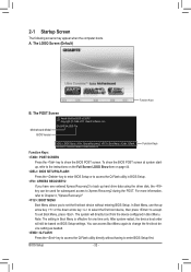
... restart, the device boot order will directly boot from the device configured in Boot Menu is effective for subsequent access to accept. GA-990FXA-UD5 F1a . . . . : BIOS Setup : XpressRecovery2 : Boot Menu : Qflash 04/26/2011-RD990-SB950-7A66FG04C-00 Function Keys Function Keys: : POST SCREEN Press... the key to show the BIOS POST screen at system startup, refer to access the Q-Flash utility directly without entering BIOS Setup. Note: The setting in Boot Menu. For more information, refer to Chapter 4, "...
... restart, the device boot order will directly boot from the device configured in Boot Menu is effective for subsequent access to accept. GA-990FXA-UD5 F1a . . . . : BIOS Setup : XpressRecovery2 : Boot Menu : Qflash 04/26/2011-RD990-SB950-7A66FG04C-00 Function Keys Function Keys: : POST SCREEN Press... the key to show the BIOS POST screen at system startup, refer to access the Q-Flash utility directly without entering BIOS Setup. Note: The setting in Boot Menu. For more information, refer to Chapter 4, "...
Manual
Page 33
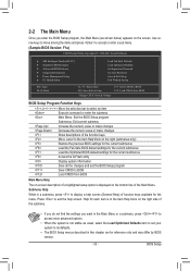
... menu. Press to exit the help screen (General Help) of the submenu. • If you do not find the settings you enter the BIOS Setup program, the Main Menu (as usual, select the Load Optimized Defaults item to set your system to its defaults. • The... chapter are for the current submenus Access the Q-Flash utility Display system information Save all the changes and exit the BIOS Setup program Save CMOS to BIOS Load CMOS from BIOS BIOS Setup Program Function Keys Move the selection bar to select an item Execute command or enter the submenu Main Menu:...
... menu. Press to exit the help screen (General Help) of the submenu. • If you do not find the settings you enter the BIOS Setup program, the Main Menu (as usual, select the Load Optimized Defaults item to set your system to its defaults. • The... chapter are for the current submenus Access the Q-Flash utility Display system information Save all the changes and exit the BIOS Setup program Save CMOS to BIOS Load CMOS from BIOS BIOS Setup Program Function Keys Move the selection bar to select an item Execute command or enter the submenu Main Menu:...
Manual
Page 34
..., and integrated LAN, etc. Power Management Setup Use this menu to configure all the power-saving functions. PC Health Status Use this task.) BIOS Setup - 34 - A user password only allows you can create up to 8 profiles (Profile 1-8) and name each profile. You can use the SPACE key)... and then press to complete. F12: Load CMOS from BIOS If your CPU, memory, etc. Standard CMOS Features Use this menu to configure the system time and date, hard drive types, and the type...
..., and integrated LAN, etc. Power Management Setup Use this menu to configure all the power-saving functions. PC Health Status Use this task.) BIOS Setup - 34 - A user password only allows you can create up to 8 profiles (Profile 1-8) and name each profile. You can use the SPACE key)... and then press to complete. F12: Load CMOS from BIOS If your CPU, memory, etc. Standard CMOS Features Use this menu to configure the system time and date, hard drive types, and the type...
Manual
Page 35
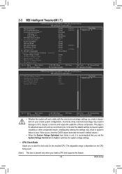
... and we recommend you set the System Voltage Control item to Auto to CPU, chipset, or memory and reduce the useful life of these components. BIOS Setup 2-3 MB Intelligent Tweaker(M.I.T.) CMOS Setup Utility-Copyright (C) 1984-2011 Award Software MB Intelligent Tweaker(M.I .T.) x HT Link Voltage Control x NB/PCIe/PLL Voltage Control x CPU...
... and we recommend you set the System Voltage Control item to Auto to CPU, chipset, or memory and reduce the useful life of these components. BIOS Setup 2-3 MB Intelligent Tweaker(M.I.T.) CMOS Setup Utility-Copyright (C) 1984-2011 Award Software MB Intelligent Tweaker(M.I .T.) x HT Link Voltage Control x NB/PCIe/PLL Voltage Control x CPU...
Manual
Page 36
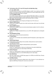
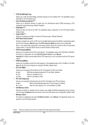
... Link between the CPU and chipset. This option is configurable only when CPU Host Clock Control is highly recommended that supports this feature. Auto BIOS will automatically adjust the HT Link Frequency. (Default) x1~x10 Sets HT Link Frequency to manually set to 150 MHz. The adjustable range... is present only when you to x1~x10 (200 MHz~2.0 GHz). The adjustable range is from 100 MHz to Manual. BIOS Setup - 36 - The adjustable range is dependent on the CPU being used. The adjustable range is set the frequency for the installed CPU. ...
... Link between the CPU and chipset. This option is configurable only when CPU Host Clock Control is highly recommended that supports this feature. Auto BIOS will automatically adjust the HT Link Frequency. (Default) x1~x10 Sets HT Link Frequency to manually set to 150 MHz. The adjustable range... is present only when you to x1~x10 (200 MHz~2.0 GHz). The adjustable range is from 100 MHz to Manual. BIOS Setup - 36 - The adjustable range is dependent on the CPU being used. The adjustable range is set the frequency for the installed CPU. ...
Manual
Page 37
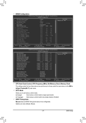
... configurable. Unganged Sets memory control mode to two single-channel. (Default) DDR3 Timing Items Manual allows all DDR3 Timing items below to single dual-channel. BIOS Setup DRAM Configuration CMOS Setup Utility-Copyright (C) 1984-2011 Award Software DRAM Configuration CPU Host Clock Control x CPU Frequency(MHz) Set Memory Clock x Memory Clock...
... configurable. Unganged Sets memory control mode to two single-channel. (Default) DDR3 Timing Items Manual allows all DDR3 Timing items below to single dual-channel. BIOS Setup DRAM Configuration CMOS Setup Utility-Copyright (C) 1984-2011 Award Software DRAM Configuration CPU Host Clock Control x CPU Frequency(MHz) Set Memory Clock x Memory Clock...
Manual
Page 38
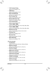
... are : Auto (default), 4T~10T. Precharge Time Options are : Auto (default), 1.0x, 1.25x, 1.5x, 2.0x. Addr/Cmd Drive Strength Options are : Auto (default), 10T~56T. BIOS Setup - 38 - Row Cycle Time Options are : Auto (default), 1.0x, 1.25x, 1.5x, 2.0x. Row Precharge Time Options are : Auto (default), 8T~40T. RAS to RAS...
... are : Auto (default), 4T~10T. Precharge Time Options are : Auto (default), 1.0x, 1.25x, 1.5x, 2.0x. Addr/Cmd Drive Strength Options are : Auto (default), 10T~56T. BIOS Setup - 38 - Row Cycle Time Options are : Auto (default), 1.0x, 1.25x, 1.5x, 2.0x. Row Precharge Time Options are : Auto (default), 8T~40T. RAS to RAS...


