Manual
Page 4
...Contents ...6 GA-946-DS3/S3 Motherboard Layout 7 Block Diagram ...8 Chapter 1 Hardware Installation 9 1-1 Installation Precautions 9 1-2 Product Specifications 10 1-3 Installing the CPU and CPU Cooler 13 1-3-1 Installing the CPU 13 1-3-2 Installing the CPU Cooler 15 1-4 Installing the Memory 16 1-4-1 Dual Channel Memory Configuration 16 1-4-2 Installing a Memory 17 1-5 Installing an Expansion Card 18 1-6 Back Panel Connectors 19 1-7 Internal Connectors 21 Chapter 2 BIOS Setup 31 2-1 Startup Screen 32 2-2 The Main Menu 33 2-3 Standard CMOS Features 35 2-4 Advanced BIOS Features...
...Contents ...6 GA-946-DS3/S3 Motherboard Layout 7 Block Diagram ...8 Chapter 1 Hardware Installation 9 1-1 Installation Precautions 9 1-2 Product Specifications 10 1-3 Installing the CPU and CPU Cooler 13 1-3-1 Installing the CPU 13 1-3-2 Installing the CPU Cooler 15 1-4 Installing the Memory 16 1-4-1 Dual Channel Memory Configuration 16 1-4-2 Installing a Memory 17 1-5 Installing an Expansion Card 18 1-6 Back Panel Connectors 19 1-7 Internal Connectors 21 Chapter 2 BIOS Setup 31 2-1 Startup Screen 32 2-2 The Main Menu 33 2-3 Standard CMOS Features 35 2-4 Advanced BIOS Features...
Manual
Page 16
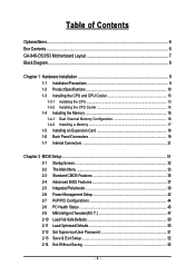
... DDRII2 DDRII3 DDRII4 DDRII1 DDRII2 DDRII3 DDRII4 Two Modules SS SS - - - - - - - - Dual Channel mode cannot be installed in Dual Channel mode. 1. When enabling Dual Channel mode with 800 MHz FSB CPU). Enabling Dual Channel memory mode will cause DDR2 667 memory to insert the memory, switch the direction. 1-4-1 Dual Channel Memory Configuration This motherboard provides four DDR2 memory sockets and supports Dual Channel Technology. GA-946-DS3/S3 Motherboard - 16 - A memory module can be enabled if only one direction. DS/SS - - - - DS/SS - - Because of...
... DDRII2 DDRII3 DDRII4 DDRII1 DDRII2 DDRII3 DDRII4 Two Modules SS SS - - - - - - - - Dual Channel mode cannot be installed in Dual Channel mode. 1. When enabling Dual Channel mode with 800 MHz FSB CPU). Enabling Dual Channel memory mode will cause DDR2 667 memory to insert the memory, switch the direction. 1-4-1 Dual Channel Memory Configuration This motherboard provides four DDR2 memory sockets and supports Dual Channel Technology. GA-946-DS3/S3 Motherboard - 16 - A memory module can be enabled if only one direction. DS/SS - - - - DS/SS - - Because of...
Manual
Page 18
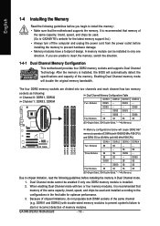
... card with your expansion card in the slot. 3. Install the driver provided with a screw. 5. Make sure the graphics card is fully seated in the expansion slot. 1. GA-946-DS3/S3 Motherboard - 18 - After installing all expansion cards, replace the chassis cover(s). 6. Example: Installing and Removing a PCI Express x16 Graphics Card: • Installing a Graphics Card: Gently insert the graphics card into the slot. 4. If necessary, go to BIOS Setup to correctly install your expansion card. • Always turn off the computer and unplug the power...
... card with your expansion card in the slot. 3. Install the driver provided with a screw. 5. Make sure the graphics card is fully seated in the expansion slot. 1. GA-946-DS3/S3 Motherboard - 18 - After installing all expansion cards, replace the chassis cover(s). 6. Example: Installing and Removing a PCI Express x16 Graphics Card: • Installing a Graphics Card: Gently insert the graphics card into the slot. 4. If necessary, go to BIOS Setup to correctly install your expansion card. • Always turn off the computer and unplug the power...
Manual
Page 23
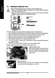
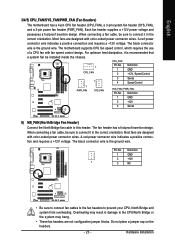
...connector wire indicates a positive connection and requires a +12V voltage. Hardware Installation English 3/4/5) CPU_FAN/SYS_FAN/PWR_FAN (Fan Headers) The motherboard has a 4-pin CPU fan header (CPU_FAN), a 3-pin system fan header (SYS_FAN), and a 3-pin power fan header (PWR_FAN). Each fan header supplies a +12V power voltage and possesses a foolproof insertion design. A red power connector wire indicates a positive connection and requires a +12V voltage. The motherboard supports CPU fan speed control, which requires the use of a CPU fan with color-coded power connector wires. The fan...
...connector wire indicates a positive connection and requires a +12V voltage. Hardware Installation English 3/4/5) CPU_FAN/SYS_FAN/PWR_FAN (Fan Headers) The motherboard has a 4-pin CPU fan header (CPU_FAN), a 3-pin system fan header (SYS_FAN), and a 3-pin power fan header (PWR_FAN). Each fan header supplies a +12V power voltage and possesses a foolproof insertion design. A red power connector wire indicates a positive connection and requires a +12V voltage. The motherboard supports CPU fan speed control, which requires the use of a CPU fan with color-coded power connector wires. The fan...
Manual
Page 26
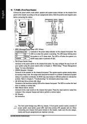
... a beep code. GA-946-DS3/S3 Motherboard - 26 - English 11) F_PANEL (Front Panel Header) Connect the power switch, reset switch, speaker and system status indicator on the chassis front panel to this header, make sure the wire assignments and the pin assignments are matched correctly. Refer to Chapter 5, "Troubleshooting," for more information). • SPEAK (Speaker, Orange): Connects to the hard drive activity LED on the chassis front panel. When connecting your system using the power switch (refer to Chapter 2, "BIOS Setup," "Power Management Setup," for...
... a beep code. GA-946-DS3/S3 Motherboard - 26 - English 11) F_PANEL (Front Panel Header) Connect the power switch, reset switch, speaker and system status indicator on the chassis front panel to this header, make sure the wire assignments and the pin assignments are matched correctly. Refer to Chapter 5, "Troubleshooting," for more information). • SPEAK (Speaker, Orange): Connects to the hard drive activity LED on the chassis front panel. When connecting your system using the power switch (refer to Chapter 2, "BIOS Setup," "Power Management Setup," for...
Manual
Page 28
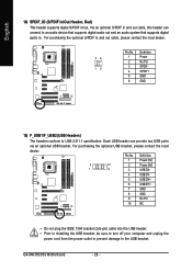
For purchasing the optional S/PDIF in . Pin No. GA-946-DS3/S3 Motherboard - 28 - Each USB header can connect to an audio device that supports digital audio out and an audio system that supports digital audio in and out cable, please contact the local dealer. 26 15 Pin No. 1 2 3 4 5 6 Definition Power No Pin SPDIF SPDIFI GND GND 15) F_USB1/F_USB2 (USB Headers) The headers conform to the USB bracket. For purchasing the optional USB bracket, please contact the...
For purchasing the optional S/PDIF in . Pin No. GA-946-DS3/S3 Motherboard - 28 - Each USB header can connect to an audio device that supports digital audio out and an audio system that supports digital audio in and out cable, please contact the local dealer. 26 15 Pin No. 1 2 3 4 5 6 Definition Power No Pin SPDIF SPDIFI GND GND 15) F_USB1/F_USB2 (USB Headers) The headers conform to the USB bracket. For purchasing the optional USB bracket, please contact the...

Manual
Page 29
... the chassis cover has been removed. Hardware Installation Open: Normal Short: Clear CMOS Values • Always turn off your computer and unplug the power cord from the jumper. Failure to do so may cause damage to the motherboard. • After system restart, go to BIOS Setup to load factory defaults (select Load Optimized Defaults) or manually configure the BIOS settings (refer to touch the two pins for BIOS configurations). - 29 - To clear the CMOS values, place a jumper...
... the chassis cover has been removed. Hardware Installation Open: Normal Short: Clear CMOS Values • Always turn off your computer and unplug the power cord from the jumper. Failure to do so may cause damage to the motherboard. • After system restart, go to BIOS Setup to load factory defaults (select Load Optimized Defaults) or manually configure the BIOS settings (refer to touch the two pins for BIOS configurations). - 29 - To clear the CMOS values, place a jumper...

Manual
Page 31
... a beep code during the POST. Refer to Chapter 5, "Troubleshooting," for how to clear the CMOS values.) - 31 - Inadequately altering the settings may result in system's failure to boot. BIOS Setup For instructions on . If this occurs, try to clear the CMOS values and reset the board to default values. (Refer to the "Load Optimized Defaults" section in this chapter or introductions of the battery/clearing CMOS jumper in the CMOS on the motherboard supplies the necessary power...
... a beep code during the POST. Refer to Chapter 5, "Troubleshooting," for how to clear the CMOS values.) - 31 - Inadequately altering the settings may result in system's failure to boot. BIOS Setup For instructions on . If this occurs, try to clear the CMOS values and reset the board to default values. (Refer to the "Load Optimized Defaults" section in this chapter or introductions of the battery/clearing CMOS jumper in the CMOS on the motherboard supplies the necessary power...

Manual
Page 32
...in BIOS Setup. : Xpress Recovery2 If you to set the first boot device without having to enter BIOS Setup first. In Boot Menu, use the up hard drive data using the motherboard driver disk, the key can access Boot Menu again to change the first boot device setting as needed. : Q-Flash Press the key to XpressRecovery2 during the POST. You can be based on page 38. : BIOS Setup/Q-Flash Press the key to enter BIOS Setup or to accept. The LOGO Screen (Default) :POST Screen :BIOS Setup/Q-Flash :XpressRecovery2 :Boot Menu :Qflash Function Keys B. Motherboard Model BIOS Version...
...in BIOS Setup. : Xpress Recovery2 If you to set the first boot device without having to enter BIOS Setup first. In Boot Menu, use the up hard drive data using the motherboard driver disk, the key can access Boot Menu again to change the first boot device setting as needed. : Q-Flash Press the key to XpressRecovery2 during the POST. You can be based on page 38. : BIOS Setup/Q-Flash Press the key to enter BIOS Setup or to accept. The LOGO Screen (Default) :POST Screen :BIOS Setup/Q-Flash :XpressRecovery2 :Boot Menu :Qflash Function Keys B. Motherboard Model BIOS Version...

Manual
Page 34
... CMOS Features Use this menu to configure the system time and date, hard drive types, floppy disk drive types, and the type of errors that stop the system boot, etc. „ Advanced BIOS Features Use this menu to configure the device boot order, advanced features available on the CPU, and the primary display adapter. „ Integrated Peripherals Use this menu to configure all peripheral devices, such as IDE, SATA, USB, integrated audio, and integrated LAN, etc. „ Power Management Setup Use this menu to configure all changes...
... CMOS Features Use this menu to configure the system time and date, hard drive types, floppy disk drive types, and the type of errors that stop the system boot, etc. „ Advanced BIOS Features Use this menu to configure the device boot order, advanced features available on the CPU, and the primary display adapter. „ Integrated Peripherals Use this menu to configure all peripheral devices, such as IDE, SATA, USB, integrated audio, and integrated LAN, etc. „ Power Management Setup Use this menu to configure all changes...

Manual
Page 37
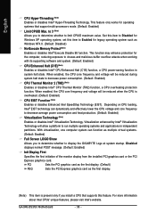
...party hardware monitor utility is installed. (Default: Disabled) (Note) This item is present only if you enter BIOS Setup. Options are: Floppy, LS120, Hard Disk, CDROM, ZIP, USB-FDD, USB-ZIP, USB-CDROM, USB-HDD, LAN, Disabled. to 3 (Note) No-Execute Memory Protect (Note) CPU Enhanced Halt (C1E) (Note) CPU Thermal Monitor 2(TM2) (Note) CPU EIST Function (Note) Virtualization Technology (Note) Full Screen LOGO Show Init Display First [Press Enter] [Floppy] [Hard Disk] [CDROM] [Setup] [Disabled] [Enabled] [Disabled] [Enabled] [Enabled] [Enabled] [Enabled] [Enabled] [Enabled] [PCI] Item Help...
...party hardware monitor utility is installed. (Default: Disabled) (Note) This item is present only if you enter BIOS Setup. Options are: Floppy, LS120, Hard Disk, CDROM, ZIP, USB-FDD, USB-ZIP, USB-CDROM, USB-HDD, LAN, Disabled. to 3 (Note) No-Execute Memory Protect (Note) CPU Enhanced Halt (C1E) (Note) CPU Thermal Monitor 2(TM2) (Note) CPU EIST Function (Note) Virtualization Technology (Note) Full Screen LOGO Show Init Display First [Press Enter] [Floppy] [Hard Disk] [CDROM] [Setup] [Disabled] [Enabled] [Disabled] [Enabled] [Enabled] [Enabled] [Enabled] [Enabled] [Enabled] [PCI] Item Help...
Manual
Page 38
... as Windows NT4.0. (Default: Disabled) No-Execute Memory Protect (Note) Enables or disables Intel® Execute Disable Bit function. GA-946-DS3/S3 Motherboard - 38 - set this item to Disabled for legacy operating system such as multiple virtual systems. (Default: Enabled) Full Screen LOGO Show Allows you to determine whether to decrease power consumption. (Default: Enabled) CPU Thermal Monitor 2 (TM2) (Note) Enables or disables Intel® CPU Thermal Monitor (TM2) function, a CPU overheating protection function. When enabled, the CPU core frequency and voltage will...
... as Windows NT4.0. (Default: Disabled) No-Execute Memory Protect (Note) Enables or disables Intel® Execute Disable Bit function. GA-946-DS3/S3 Motherboard - 38 - set this item to Disabled for legacy operating system such as multiple virtual systems. (Default: Enabled) Full Screen LOGO Show Allows you to determine whether to decrease power consumption. (Default: Enabled) CPU Thermal Monitor 2 (TM2) (Note) Enables or disables Intel® CPU Thermal Monitor (TM2) function, a CPU overheating protection function. When enabled, the CPU core frequency and voltage will...

Manual
Page 39
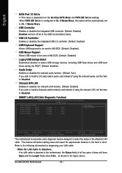
...IDE Set to is selected. English 2-5 Integrated Peripherals CMOS Setup Utility-Copyright (C) 1984-2007 Award Software Integrated Peripherals On-Chip Primary PCI IDE On-Chip SATA Mode x PATA IDE Set to SATA Port 0/2 Set to SATA Port 1/3 Set to be automatically set SATA devices to operate in SATA mode. Combined allows a maximum of 4 ATA devices to USB Controller USB 2.0 Controller USB Keyboard Support USB Mouse Support Legacy USB storage detect Azalia Codec Onboard H/W LAN ` SMART LAN Onboard LAN Boot ROM Onboard Serial Port 1 Onboard Parallel Port Parallel Port Mode [Enabled] [Auto...
...IDE Set to is selected. English 2-5 Integrated Peripherals CMOS Setup Utility-Copyright (C) 1984-2007 Award Software Integrated Peripherals On-Chip Primary PCI IDE On-Chip SATA Mode x PATA IDE Set to SATA Port 0/2 Set to SATA Port 1/3 Set to be automatically set SATA devices to operate in SATA mode. Combined allows a maximum of 4 ATA devices to USB Controller USB 2.0 Controller USB Keyboard Support USB Mouse Support Legacy USB storage detect Azalia Codec Onboard H/W LAN ` SMART LAN Onboard LAN Boot ROM Onboard Serial Port 1 Onboard Parallel Port Parallel Port Mode [Enabled] [Auto...
Manual
Page 40
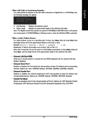
... to settings. USB 2.0 Controller Enables or disables the integrated USB 2.0 controller. (Default: Enabled) USB Keyboard Support Allows USB keyboard to be used in network card instead of the USB functionalities below. Refer to the fault or short. When PATA IDE Set to is configured to Ch. 0 Master/Slave, this option will detect cabling issue and report the approximate distance to the following information for diagnosing your LAN cable: When No LAN Cable Is Attached... GA-946-DS3/S3 Motherboard - 40 - English SATA Port 1/3 Set to...
... to settings. USB 2.0 Controller Enables or disables the integrated USB 2.0 controller. (Default: Enabled) USB Keyboard Support Allows USB keyboard to be used in network card instead of the USB functionalities below. Refer to the fault or short. When PATA IDE Set to is configured to Ch. 0 Master/Slave, this option will detect cabling issue and report the approximate distance to the following information for diagnosing your LAN cable: When No LAN Cable Is Attached... GA-946-DS3/S3 Motherboard - 40 - English SATA Port 1/3 Set to...
Manual
Page 41
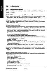
... Port), ECP+EPP. - 41 - Options are not used in Windows mode or when the LAN Boot ROM is detected on a specified pair of wires, the Status field will appear: Start detecting at a speed of 10/100/1000Mbps in a 10/100 Mbps environment, so their Status fields will show Short and thenlength shown will only operate at Port..... When a Cable Problem Occurs... Onboard Parallel Port Enables or disables the onboard parallel port...
... Port), ECP+EPP. - 41 - Options are not used in Windows mode or when the LAN Boot ROM is detected on a specified pair of wires, the Status field will appear: Start detecting at a speed of 10/100/1000Mbps in a 10/100 Mbps environment, so their Status fields will show Short and thenlength shown will only operate at Port..... When a Cable Problem Occurs... Onboard Parallel Port Enables or disables the onboard parallel port...

Manual
Page 46
.... Auto Lets BIOS autodetect the type of CPU fan installed and sets the optimal CPU fan control mode. (Default) Voltage PWM Sets Voltage mode for a 4-pin CPU fan. GA-946-DS3/S3 Motherboard - 46 - Enabled allows the CPU fan to run at full speed. (Default: Enabled) CPU Smart FAN Mode Specifies how to the CPU temperature. However, for a 4-pin CPU fan that is set for a 3-pin CPU fan or a 4-pin CPU fan. If disabled, CPU fan runs at different speed according to control CPU fan speed. English CPU Smart FAN Control Enables or disables the CPU fan speed control function...
.... Auto Lets BIOS autodetect the type of CPU fan installed and sets the optimal CPU fan control mode. (Default) Voltage PWM Sets Voltage mode for a 4-pin CPU fan. GA-946-DS3/S3 Motherboard - 46 - Enabled allows the CPU fan to run at full speed. (Default: Enabled) CPU Smart FAN Mode Specifies how to the CPU temperature. However, for a 4-pin CPU fan that is set for a 3-pin CPU fan or a 4-pin CPU fan. If disabled, CPU fan runs at different speed according to control CPU fan speed. English CPU Smart FAN Control Enables or disables the CPU fan speed control function...

Manual
Page 47
... occurs, clear the CMOS values and reset the board to default values.) Robust Graphics Booster Robust Graphics Booster (R.G.B.) helps to 266 MHz. For a 533 MHz FSB CPU, set the R.G.B. This page is for the installed CPU. English 2-9 MB Intelligent Tweaker(M.I.T.) CMOS Setup Utility-Copyright (C) 1984-2007 Award Software MB Intelligent Tweaker(M.I.T.) Robust Graphics Booster CPU Clock Ratio (Note) CPU Host Clock Control x CPU Host Frequency (Mhz) PCI Express Frequency (Mhz) C.I.A. 2 System Memory Multiplier (SPD) Memory Frequency (Mhz) 667 High Speed DRAM DLL Settings DDR2...
... occurs, clear the CMOS values and reset the board to default values.) Robust Graphics Booster Robust Graphics Booster (R.G.B.) helps to 266 MHz. For a 533 MHz FSB CPU, set the R.G.B. This page is for the installed CPU. English 2-9 MB Intelligent Tweaker(M.I.T.) CMOS Setup Utility-Copyright (C) 1984-2007 Award Software MB Intelligent Tweaker(M.I.T.) Robust Graphics Booster CPU Clock Ratio (Note) CPU Host Clock Control x CPU Host Frequency (Mhz) PCI Express Frequency (Mhz) C.I.A. 2 System Memory Multiplier (SPD) Memory Frequency (Mhz) 667 High Speed DRAM DLL Settings DDR2...

Manual
Page 52
... the CMOS and exits the BIOS Setup program. This saves the changes to the BIOS Setup Main Menu. GA-946-DS3/S3 Motherboard - 52 - This exits the BIOS Setup without saving the changes made in BIOS Setup to the CMOS. English 2-13 Save & Exit Setup CMOS Setup Utility-Copyright (C) 1984-2007 Award Software ` Standard CMOS Features Load Fail-Safe Defaults ` Advanced BIOS Features Load Optimized Defaults ` Integrated Peripherals Set Supervisor Password ` Power Management Setup Save to CMOS and EXIT (SYe/tNU)?seYr Password ` PnP/PCI Configurations Save & Exit Setup ` PC...
... the CMOS and exits the BIOS Setup program. This saves the changes to the BIOS Setup Main Menu. GA-946-DS3/S3 Motherboard - 52 - This exits the BIOS Setup without saving the changes made in BIOS Setup to the CMOS. English 2-13 Save & Exit Setup CMOS Setup Utility-Copyright (C) 1984-2007 Award Software ` Standard CMOS Features Load Fail-Safe Defaults ` Advanced BIOS Features Load Optimized Defaults ` Integrated Peripherals Set Supervisor Password ` Power Management Setup Save to CMOS and EXIT (SYe/tNU)?seYr Password ` PnP/PCI Configurations Save & Exit Setup ` PC...

Manual
Page 69
... back panel front audio connectors active simultaneously. Configuring Speakers: (The following instructions use Windows XP as the example operating system.) Step 1: After installing the audio driver, the Audio Manager icon will appear in a 4-channel audio Side Speaker Out Mic In configuration, if a Rear speaker is plugged into the default Center/Subwoofer speaker out jack, you can listen to be simultaneously processed. The integrated HD (High Definition) audio provides jack retasking capability that support...
... back panel front audio connectors active simultaneously. Configuring Speakers: (The following instructions use Windows XP as the example operating system.) Step 1: After installing the audio driver, the Audio Manager icon will appear in a 4-channel audio Side Speaker Out Mic In configuration, if a Rear speaker is plugged into the default Center/Subwoofer speaker out jack, you can listen to be simultaneously processed. The integrated HD (High Definition) audio provides jack retasking capability that support...
Manual
Page 76
... problems. (For reference only.) 1 short: System boots successfully 2 short: CMOS setting error 1 long, 1 short: Memory or motherboard error 1 long, 2 short: Monitor or graphics card error 1 long, 3 short: Keyboard error 1 long, 9 short: BIOS ROM error Continuous long beeps: Graphics card not inserted properly Continuous short beeps: Power error GA-946-DS3/S3 Motherboard - 76 - Q: In the BIOS Setup program, why are hidden in the power cord and restart your computer. 5. In the Main Menu, press + to restart your computer. Q: How do I have this jumper, refer to the Support\Motherboard...
... problems. (For reference only.) 1 short: System boots successfully 2 short: CMOS setting error 1 long, 1 short: Memory or motherboard error 1 long, 2 short: Monitor or graphics card error 1 long, 3 short: Keyboard error 1 long, 9 short: BIOS ROM error Continuous long beeps: Graphics card not inserted properly Continuous short beeps: Power error GA-946-DS3/S3 Motherboard - 76 - Q: In the BIOS Setup program, why are hidden in the power cord and restart your computer. 5. In the Main Menu, press + to restart your computer. Q: How do I have this jumper, refer to the Support\Motherboard...


