Manual
Page 5
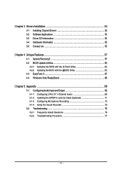
... 4-3 EasyTune 5 ...67 4-4 Windows Vista ReadyBoost 68 Chapter 5 Appendix ...69 5-1 Configuring Audio Input and Output 69 5-1-1 Configuring 2/4/5.1/7.1-Channel Audio 69 5-1-2 Installing the S/PDIF In and Out Cable (Optional 71 5-1-3 Configuring Microphone Recording 73 5-1-4 Using the Sound Recorder 75 5-2 Troubleshooting 76 5-2-1 Frequently Asked Questions 76 5-2-2 Troubleshooting Procedure 77 - 5 -
... 4-3 EasyTune 5 ...67 4-4 Windows Vista ReadyBoost 68 Chapter 5 Appendix ...69 5-1 Configuring Audio Input and Output 69 5-1-1 Configuring 2/4/5.1/7.1-Channel Audio 69 5-1-2 Installing the S/PDIF In and Out Cable (Optional 71 5-1-3 Configuring Microphone Recording 73 5-1-4 Using the Sound Recorder 75 5-2 Troubleshooting 76 5-2-1 Frequently Asked Questions 76 5-2-2 Troubleshooting Procedure 77 - 5 -
Manual
Page 6
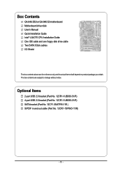
Box Contents GA-946-DS3 or GA-946-S3 motherboard Motherboard driver disk User's Manual Quick Installation Guide Intel® LGA775 CPU Installation Guide One IDE cable and one floppy disk drive cable Two SATA 3Gb/s cables I/O Shield The box contents above are subject to change without notice. Optional Items 2-port USB 2.0 bracket...51/R) 4-port USB 2.0 bracket (Part No. 12CR1-1UB030-21/R) SATA bracket (Part No. 12CF1-3SATPW-11R ) S/PDIF in and out cable (Part No. 12CR1-1SPINO-11/R) - 6 - The box contents are for reference only and the actual items shall depend on product package you obtain....
Box Contents GA-946-DS3 or GA-946-S3 motherboard Motherboard driver disk User's Manual Quick Installation Guide Intel® LGA775 CPU Installation Guide One IDE cable and one floppy disk drive cable Two SATA 3Gb/s cables I/O Shield The box contents above are subject to change without notice. Optional Items 2-port USB 2.0 bracket...51/R) 4-port USB 2.0 bracket (Part No. 12CR1-1UB030-21/R) SATA bracket (Part No. 12CF1-3SATPW-11R ) S/PDIF in and out cable (Part No. 12CR1-1SPINO-11/R) - 6 - The box contents are for reference only and the actual items shall depend on product package you obtain....

Manual
Page 9
...any installation steps or have it on top of an antistatic pad or within a electrostatic shielding container. • Before unplugging the power supply cable from the motherboard, make sure the power supply has been turned off. • Before turning on the power, make sure the power supply... voltage has been set according to the local voltage standard. • Before using the product, please verify that all cables and power connectors of your hardware components are connected. • To prevent damage to the motherboard, do not remove or break motherboard S/N (...
...any installation steps or have it on top of an antistatic pad or within a electrostatic shielding container. • Before unplugging the power supply cable from the motherboard, make sure the power supply has been turned off. • Before turning on the power, make sure the power supply... voltage has been set according to the local voltage standard. • Before using the product, please verify that all cables and power connectors of your hardware components are connected. • To prevent damage to the motherboard, do not remove or break motherboard S/N (...

Manual
Page 19
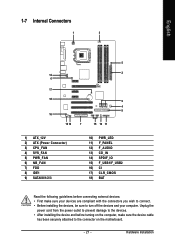
... etc. Do not rock it side to side to a back panel connector, first remove the cable from your device and then remove it from the motherboard. • When removing the cable, pull it straight out from the connector. Serial Port Use the serial port to connect rear speakers...Parallel Port Use the parallel port to connect center/subwoofer speakers in a 7.1-channel audio configuration. • When removing the cable connected to prevent an electrical short inside the cable connector. - 19 - The parallel port is occurring Center/Subwoofer Speaker Out Jack (Orange) Use this audio jack to ...
... etc. Do not rock it side to side to a back panel connector, first remove the cable from your device and then remove it from the motherboard. • When removing the cable, pull it straight out from the connector. Serial Port Use the serial port to connect rear speakers...Parallel Port Use the parallel port to connect center/subwoofer speakers in a 7.1-channel audio configuration. • When removing the cable connected to prevent an electrical short inside the cable connector. - 19 - The parallel port is occurring Center/Subwoofer Speaker Out Jack (Orange) Use this audio jack to ...
Manual
Page 21
... compliant with the connectors you wish to connect. • Before installing the devices, be sure to the connector on the computer, make sure the device cable has been securely attached to turn off the devices and your computer.
... compliant with the connectors you wish to connect. • Before installing the devices, be sure to the connector on the computer, make sure the device cable has been securely attached to turn off the devices and your computer.

Manual
Page 22
... the CPU. If a power supply is used that can withstand high power consumption be used (400W or greater). Do not insert the power supply cable into pins under the protective cover when using a 2x12 power supply, remove the protective cover from the main power connector on the motherboard. If the ... 3.3V -12V GND PS_ON(soft On/Off) GND GND GND -5V +5V +5V +5V (Only for 2x12-pin ATX) GND (Only for 2x12-pin ATX) GA-946-DS3/S3 Motherboard - 22 - English 1/2) ATX_12V_2X/ATX (2x2 12V Power Connector and 2x12 Main Power Connector) With the use of the power connector, the power supply...
... the CPU. If a power supply is used that can withstand high power consumption be used (400W or greater). Do not insert the power supply cable into pins under the protective cover when using a 2x12 power supply, remove the protective cover from the main power connector on the motherboard. If the ... 3.3V -12V GND PS_ON(soft On/Off) GND GND GND -5V +5V +5V +5V (Only for 2x12-pin ATX) GND (Only for 2x12-pin ATX) GA-946-DS3/S3 Motherboard - 22 - English 1/2) ATX_12V_2X/ATX (2x2 12V Power Connector and 2x12 Main Power Connector) With the use of the power connector, the power supply...
Manual
Page 23
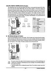
... headers are not configuration jumper blocks. Definition 1 GND 2 +12V 3 Sense 6) NB_FAN (North Bridge Fan Header) Connect the North Bridge fan cable to prevent your CPU, North Bridge and system from overheating. A red power connector wire indicates a positive connection and requires a +12V voltage. Hardware... Installation Most fans are designed with color-coded power connector wires. When connecting a fan cable, be sure to connect it in damage to connect it is the ground wire. Each fan header supplies a +12V power voltage ...
... headers are not configuration jumper blocks. Definition 1 GND 2 +12V 3 Sense 6) NB_FAN (North Bridge Fan Header) Connect the North Bridge fan cable to prevent your CPU, North Bridge and system from overheating. A red power connector wire indicates a positive connection and requires a +12V voltage. Hardware... Installation Most fans are designed with color-coded power connector wires. When connecting a fan cable, be sure to connect it in damage to connect it is the ground wire. Each fan header supplies a +12V power voltage ...
Manual
Page 24
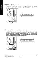
If you wish to connect two IDE devices, remember to set the jumpers and the cabling according to connect a floppy disk drive. English 7) FDD (Floppy Disk Drive Connector) This connector is used to the role of floppy disk drives supported...master/slave settings for the IDE devices, read the instructions from the device manufacturers.) 2 40 1 39 GA-946-DS3/S3 Motherboard - 24 - Before connecting a floppy disk drive, locate the foolproof groove on the connector. Before attaching the IDE cable, locate the foolproof groove on the connector. 33 1 34 2 8) IDE1 (IDE Connector) The ...
If you wish to connect two IDE devices, remember to set the jumpers and the cabling according to connect a floppy disk drive. English 7) FDD (Floppy Disk Drive Connector) This connector is used to the role of floppy disk drives supported...master/slave settings for the IDE devices, read the instructions from the device manufacturers.) 2 40 1 39 GA-946-DS3/S3 Motherboard - 24 - Before connecting a floppy disk drive, locate the foolproof groove on the connector. Before attaching the IDE cable, locate the foolproof groove on the connector. 33 1 34 2 8) IDE1 (IDE Connector) The ...
Manual
Page 26
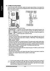
... to the pin assignments below. Press the reset switch to restart the computer if the computer freezes and fails to indicate the problem. GA-946-DS3/S3 Motherboard - 26 - The LED is off when the system is on the chassis front panel. The LED keeps blinking when S1... the system is detected at system startup. The system reports system startup status by chassis. Note the positive and negative pins before connecting the cables. Refer to Chapter 5, "Troubleshooting," for more information). • SPEAK (Speaker, Orange): Connects to the power status indicator on when the...
... to the pin assignments below. Press the reset switch to restart the computer if the computer freezes and fails to indicate the problem. GA-946-DS3/S3 Motherboard - 26 - The LED is off when the system is on the chassis front panel. The LED keeps blinking when S1... the system is detected at system startup. The system reports system startup status by chassis. Note the positive and negative pins before connecting the cables. Refer to Chapter 5, "Troubleshooting," for more information). • SPEAK (Speaker, Orange): Connects to the power status indicator on when the...
Manual
Page 27
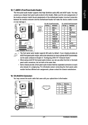
... assignments, please contact the chassis manufacturer. 13) CD_IN (CD In Connector) You may connect your optical drive to this header. You may connect the audio cable that has separated connectors on how to activate AC'97 functioninality via the audio software in Chapter 5, "Configuring 2/4/5.1/7.1-Channel Audio." • When using an AC...
... assignments, please contact the chassis manufacturer. 13) CD_IN (CD In Connector) You may connect your optical drive to this header. You may connect the audio cable that has separated connectors on how to activate AC'97 functioninality via the audio software in Chapter 5, "Configuring 2/4/5.1/7.1-Channel Audio." • When using an AC...
Manual
Page 28
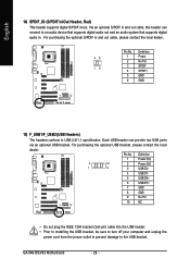
... plug the IEEE 1394 bracket (2x5-pin) cable into the USB header. • Prior to installing the USB bracket, be sure to turn off your computer and unplug the power cord from the power outlet to prevent damage to USB 2.0/1.1 specification. GA-946-DS3/S3 Motherboard - 28 - Via an optional ...S/PDIF in /out. English 14) SPDIF_IO (S/PDIF In/Out Header, Red) This header supports digital S/PDIF in and out cable, this header can provide two USB ports via an optional USB ...
... plug the IEEE 1394 bracket (2x5-pin) cable into the USB header. • Prior to installing the USB bracket, be sure to turn off your computer and unplug the power cord from the power outlet to prevent damage to USB 2.0/1.1 specification. GA-946-DS3/S3 Motherboard - 28 - Via an optional ...S/PDIF in /out. English 14) SPDIF_IO (S/PDIF In/Out Header, Red) This header supports digital S/PDIF in and out cable, this header can provide two USB ports via an optional USB ...
Manual
Page 40
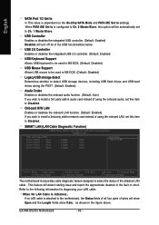
.../PD: Value F10: Save F6: Fail-Safe Defaults ESC: Exit F1: General Help F7: Optimized Defaults This motherboard incorporates cable diagnostic feature designed to Ch. 1 Master/Slave. GA-946-DS3/S3 Motherboard - 40 - Onboard H/W LAN Enables or disables the onboard LAN function. (Default: Enabled) If you wish ... 1/3 Set to This value is dependent on the On-Chip SATA Mode and PATA IDE Set to Disabled. SMART LAN (LAN Cable Diagnostic Function) CMOS Setup Utility-Copyright (C) 1984-2007 Award Software SMART LAN Start detecting at Port..... USB 2.0 Controller Enables or ...
.../PD: Value F10: Save F6: Fail-Safe Defaults ESC: Exit F1: General Help F7: Optimized Defaults This motherboard incorporates cable diagnostic feature designed to Ch. 1 Master/Slave. GA-946-DS3/S3 Motherboard - 40 - Onboard H/W LAN Enables or disables the onboard LAN function. (Default: Enabled) If you wish ... 1/3 Set to This value is dependent on the On-Chip SATA Mode and PATA IDE Set to Disabled. SMART LAN (LAN Cable Diagnostic Function) CMOS Setup Utility-Copyright (C) 1984-2007 Award Software SMART LAN Start detecting at Port..... USB 2.0 Controller Enables or ...
Manual
Page 41
...), ECP (Extended Capabilities Port), ECP+EPP. - 41 - Options are : Auto, 3F8/IRQ4 (default), 2F8/IRQ3, 3E8/IRQ4, 2E8/IRQ3, Disabled. When a Cable Problem Occurs... Onboard Parallel Port Enables or disables the onboard parallel port (LPT) and specifies its base I /O address and corresponding interrupt. BIOS Setup Example: Pair1... will operate at Port..... Options are not used in Windows mode or when the LAN Boot ROM is detected on Pair 1-2. If no cable problem is activated. it will appear: Start detecting at a normal speed of 10/100/1000Mbps in a 10/100 Mbps environment, so ...
...), ECP (Extended Capabilities Port), ECP+EPP. - 41 - Options are : Auto, 3F8/IRQ4 (default), 2F8/IRQ3, 3E8/IRQ4, 2E8/IRQ3, Disabled. When a Cable Problem Occurs... Onboard Parallel Port Enables or disables the onboard parallel port (LPT) and specifies its base I /O address and corresponding interrupt. BIOS Setup Example: Pair1... will operate at Port..... Options are not used in Windows mode or when the LAN Boot ROM is detected on Pair 1-2. If no cable problem is activated. it will appear: Start detecting at a normal speed of 10/100/1000Mbps in a 10/100 Mbps environment, so ...
Manual
Page 71
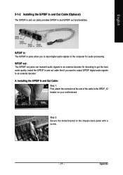
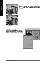
... in jacks allow you want to output S/PDIF digital audio signals to the SPDIF_IO header on your motherboard. Install the S/PDIF in and out cable first if you to input digital audio signals to the computer for decoding to the chassis back panel with a screw. - 71 - Appendix ...Installing the S/PDIF In and Out Cable: Step 1: First, attach the connector at the end of the cable to an external decoder. A. S/PDIF out: The S/PDIF out jacks can transmit audio signals to an external decoder ...
... in jacks allow you want to output S/PDIF digital audio signals to the SPDIF_IO header on your motherboard. Install the S/PDIF in and out cable first if you to input digital audio signals to the computer for decoding to the chassis back panel with a screw. - 71 - Appendix ...Installing the S/PDIF In and Out Cable: Step 1: First, attach the connector at the end of the cable to an external decoder. A. S/PDIF out: The S/PDIF out jacks can transmit audio signals to an external decoder ...
Manual
Page 72
S/PDIF Optical Cable B. Configuring S/PDIF out: Click the tool icon in the DIGITAL section. English S/PDIF Coaxial Cable Step 3: Connect a S/PDIF coaxial cable or a S/PDIF optical cable (either one) to complete the configuration. GA-946-DS3/S3 Motherboard - 72 - In the S/PDIF In/Out Settings dialog box, select an output sampling rate and select (or disable) the output source. Click OK to an external decoder for transmitting the S/PDIF digital audio signals.
S/PDIF Optical Cable B. Configuring S/PDIF out: Click the tool icon in the DIGITAL section. English S/PDIF Coaxial Cable Step 3: Connect a S/PDIF coaxial cable or a S/PDIF optical cable (either one) to complete the configuration. GA-946-DS3/S3 Motherboard - 72 - In the S/PDIF In/Out Settings dialog box, select an output sampling rate and select (or disable) the output source. Click OK to an external decoder for transmitting the S/PDIF digital audio signals.

Manual
Page 77
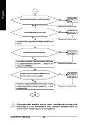
...attached to start the computer. The problem is verified and solved. The problem is verified and solved. Connect the CPU cooler power cable to the CPU_FAN header properly? Make sure the motherboard does not short-circuit with the chassis or other metal objects. Is the.... Secure the CPU No cooler on the memory slot. Yes Check if the memory is verified and solved. Remove all peripherals, connecting cables, and power cord etc. English 5-2-2 Troubleshooting Procedure If you encounter any troubles during system startup, follow the troubleshooting procedure below to solve...
...attached to start the computer. The problem is verified and solved. The problem is verified and solved. Connect the CPU cooler power cable to the CPU_FAN header properly? Make sure the motherboard does not short-circuit with the chassis or other metal objects. Is the.... Secure the CPU No cooler on the memory slot. Yes Check if the memory is verified and solved. Remove all peripherals, connecting cables, and power cord etc. English 5-2-2 Troubleshooting Procedure If you encounter any troubles during system startup, follow the troubleshooting procedure below to solve...
Manual
Page 78
.../SATA device, connector, or cable might fail. Our customer service staff will reply you as soon as possible. English A When the computer is turned on your monitor. The problem is verified and solved. No The keyboard or mouse might fail. The problem is unable to solve your question. GA-946-DS3/S3 Motherboard - 78...
.../SATA device, connector, or cable might fail. Our customer service staff will reply you as soon as possible. English A When the computer is turned on your monitor. The problem is verified and solved. No The keyboard or mouse might fail. The problem is unable to solve your question. GA-946-DS3/S3 Motherboard - 78...


