Manual
Page 10
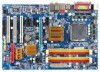
...174; Pentium® 4 processor/ Intel® Celeron® D processor in the LGA 775 package (Go to GIGABYTE's website for the latest CPU support list.) Š Support for Intel® Hyper-Threading Technology Š L2 ... DDR2 667 (Note 2)/533 MHz memory modules (Note 3) (Go to GIGABYTE's website for the latest memory support list.) Š Realtek ALC889A codec Š High Definition Audio Š 2/4/5.1/7.1-channel Š Support for S/PDIF In/Out Š...brackets connected to the internal USB headers) "*" Only the GA-946-DS3 adopts All-Solid Capacitor design. GA-946-DS3/S3 Motherboard - 10 -
...174; Pentium® 4 processor/ Intel® Celeron® D processor in the LGA 775 package (Go to GIGABYTE's website for the latest CPU support list.) Š Support for Intel® Hyper-Threading Technology Š L2 ... DDR2 667 (Note 2)/533 MHz memory modules (Note 3) (Go to GIGABYTE's website for the latest memory support list.) Š Realtek ALC889A codec Š High Definition Audio Š 2/4/5.1/7.1-channel Š Support for S/PDIF In/Out Š...brackets connected to the internal USB headers) "*" Only the GA-946-DS3 adopts All-Solid Capacitor design. GA-946-DS3/S3 Motherboard - 10 -

Manual
Page 22
... power to all devices are properly installed. When using a 2x10 power supply. 3 4 1 2 ATX_12V ATX_12V: Pin No. 1 2 3 4 Definition GND GND +12V +12V 12 24 1 13 ATX ATX: Pin No. 1 2 3 4 5 6 7 8 9 10 11 12 Definition Pin No. 3.3V 13 3.3V 14 GND 15 +5V 16 GND 17 +5V 18 GND 19 Power Good...) 21 +12V 22 +12V(Onlyfor2x12-pinATX) 23 3.3V(Onlyfor2x12-pinATX) 24 Definition 3.3V -12V GND PS_ON(soft On/Off) GND GND GND -5V +5V +5V +5V (Only for 2x12-pin ATX) GND (Only for 2x12-pin ATX) GA-946-DS3/S3 Motherboard - 22 - Do not insert the power supply cable into pins ...
... power to all devices are properly installed. When using a 2x10 power supply. 3 4 1 2 ATX_12V ATX_12V: Pin No. 1 2 3 4 Definition GND GND +12V +12V 12 24 1 13 ATX ATX: Pin No. 1 2 3 4 5 6 7 8 9 10 11 12 Definition Pin No. 3.3V 13 3.3V 14 GND 15 +5V 16 GND 17 +5V 18 GND 19 Power Good...) 21 +12V 22 +12V(Onlyfor2x12-pinATX) 23 3.3V(Onlyfor2x12-pinATX) 24 Definition 3.3V -12V GND PS_ON(soft On/Off) GND GND GND -5V +5V +5V +5V (Only for 2x12-pin ATX) GND (Only for 2x12-pin ATX) GA-946-DS3/S3 Motherboard - 22 - Do not insert the power supply cable into pins ...
Manual
Page 23
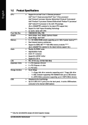
...SYS_FAN / PWR_FAN: Pin No. The motherboard supports CPU fan speed control, which requires the use of a CPU fan with color-coded power connector wires. Definition 1 GND 2 +12V 1 3 NC • Be sure to connect fan cables to the fan headers to this header. Each fan header supplies a ... wires. The black connector wire is the ground wire. The fan header has a foolproof insertion design. The black connector wire is the ground wire. Definition 1 GND 2 +12V 3 Sense 6) NB_FAN (North Bridge Fan Header) Connect the North Bridge fan cable to prevent your CPU, North Bridge and ...
...SYS_FAN / PWR_FAN: Pin No. The motherboard supports CPU fan speed control, which requires the use of a CPU fan with color-coded power connector wires. Definition 1 GND 2 +12V 1 3 NC • Be sure to connect fan cables to the fan headers to this header. Each fan header supplies a ... wires. The black connector wire is the ground wire. The fan header has a foolproof insertion design. The black connector wire is the ground wire. Definition 1 GND 2 +12V 3 Sense 6) NB_FAN (North Bridge Fan Header) Connect the North Bridge fan cable to prevent your CPU, North Bridge and ...

Manual
Page 25
...SATA connector supports a single SATA device. SATAII0 SATAII2 7 17 1 1 71 7 SATAII1 SATAII3 Pin No. 1 2 3 4 5 6 7 Definition GND TXP TXN GND RXN RXP GND 10) PWR_LED (System Power LED Header) This header can be used to connect a system power LED on.... The LED is operating. Hardware Installation English 9) SATAII0/1/2/3 (SATA 3Gb/s Connectors, Controlled by ICH7, Orange) The SATA connectors conform to indicate system power status. Definition 1 MPD+ 2 MPD- 1 3 MPD- The LED is in S1 sleep state. The LED keeps blinking when the system is in S3/S4 sleep state or...
...SATA connector supports a single SATA device. SATAII0 SATAII2 7 17 1 1 71 7 SATAII1 SATAII3 Pin No. 1 2 3 4 5 6 7 Definition GND TXP TXN GND RXN RXP GND 10) PWR_LED (System Power LED Header) This header can be used to connect a system power LED on.... The LED is operating. Hardware Installation English 9) SATAII0/1/2/3 (SATA 3Gb/s Connectors, Controlled by ICH7, Orange) The SATA connectors conform to indicate system power status. Definition 1 MPD+ 2 MPD- 1 3 MPD- The LED is in S1 sleep state. The LED keeps blinking when the system is in S3/S4 sleep state or...
Manual
Page 27
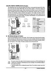
... work or even damage it. Pin No. Incorrect connection between the module connector and the motherboard header will make the device unable to the header. Definition 1 1 CD-L 2 GND 3 GND 4 CD-R - 27 - For HD Front Panel Audio: For AC'97 Front Panel Audio: 10 9 Pin No. For ...of the motherboard header. Hardware Installation English 12) F_AUDIO (Front Panel Audio Header) The front panel audio header supports Intel High Definition audio (HD) and AC'97 audio. Make sure the wire assignments of the module connector match the pin assignments of a single plug.
... work or even damage it. Pin No. Incorrect connection between the module connector and the motherboard header will make the device unable to the header. Definition 1 1 CD-L 2 GND 3 GND 4 CD-R - 27 - For HD Front Panel Audio: For AC'97 Front Panel Audio: 10 9 Pin No. For ...of the motherboard header. Hardware Installation English 12) F_AUDIO (Front Panel Audio Header) The front panel audio header supports Intel High Definition audio (HD) and AC'97 audio. Make sure the wire assignments of the module connector match the pin assignments of a single plug.
Manual
Page 28
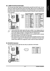
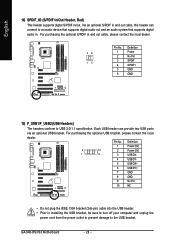
..., please contact the local dealer. GA-946-DS3/S3 Motherboard - 28 - English 14) SPDIF_IO (S/PDIF In/Out Header, Red) This header supports digital S/PDIF in . Pin No. For purchasing the optional S/PDIF in and out cable, please contact the local dealer. 26 15 Pin No. 1 2 3 4 5 6 Definition Power No Pin SPDIF SPDIFI GND ...GND 15) F_USB1/F_USB2 (USB Headers) The headers conform to the USB bracket. Definition 1 Power (5V) 2 10 1 9 2 Power (5V) 3 USB DX- 4 USB DY- 5 USB DX+ 6 USB DY+ 7 GND 8 GND 9 No Pin 10 NC • Do not plug ...
..., please contact the local dealer. GA-946-DS3/S3 Motherboard - 28 - English 14) SPDIF_IO (S/PDIF In/Out Header, Red) This header supports digital S/PDIF in . Pin No. For purchasing the optional S/PDIF in and out cable, please contact the local dealer. 26 15 Pin No. 1 2 3 4 5 6 Definition Power No Pin SPDIF SPDIFI GND ...GND 15) F_USB1/F_USB2 (USB Headers) The headers conform to the USB bracket. Definition 1 Power (5V) 2 10 1 9 2 Power (5V) 3 USB DX- 4 USB DY- 5 USB DX+ 6 USB DY+ 7 GND 8 GND 9 No Pin 10 NC • Do not plug ...

Manual
Page 29
Definition 1 1 Signal 2 GND 17) CLR_CMOS (Clearing CMOS Jumper) Use this jumper to factory defaults. date information and BIOS configurations) and reset the CMOS values to clear ...
Definition 1 1 Signal 2 GND 17) CLR_CMOS (Clearing CMOS Jumper) Use this jumper to factory defaults. date information and BIOS configurations) and reset the CMOS values to clear ...

Manual
Page 69
... music, have both the front and back panel front audio connectors active simultaneously. Appendix The integrated HD (High Definition) audio provides jack retasking capability that support 44.1KHz/ 48KHz/ 96KHz/192KHz sampling rate. High Definition Audio (HD Audio) HD Audio includes multiple high quality digital-to-analog converters (DACs) that allows Center...
... music, have both the front and back panel front audio connectors active simultaneously. Appendix The integrated HD (High Definition) audio provides jack retasking capability that support 44.1KHz/ 48KHz/ 96KHz/192KHz sampling rate. High Definition Audio (HD Audio) HD Audio includes multiple high quality digital-to-analog converters (DACs) that allows Center...
