Manual
Page 1
GA-945PLM-S2 Intel® CoreTM 2 Extreme dual-core / CoreTM 2 Duo / Intel® Pentium® D / Pentium® 4 / Celeron® D LGA775 Processor Motherboard User's Manual Rev. 6602 12ME-945PLM2R-6602R * The WEEE marking on the product indicates this product must not be disposed of with user's other household waste and must be handed over to a designated collection point for the recycling of waste electrical and electronic equipment!! * The WEEE marking applies only in European Union's member states.
GA-945PLM-S2 Intel® CoreTM 2 Extreme dual-core / CoreTM 2 Duo / Intel® Pentium® D / Pentium® 4 / Celeron® D LGA775 Processor Motherboard User's Manual Rev. 6602 12ME-945PLM2R-6602R * The WEEE marking on the product indicates this product must not be disposed of with user's other household waste and must be handed over to a designated collection point for the recycling of waste electrical and electronic equipment!! * The WEEE marking applies only in European Union's member states.
Manual
Page 2
Motherboard GA-945PLM-S2 Jan. 31, 2007 Motherboard GA-945PLM-S2 Jan. 31, 2007
Motherboard GA-945PLM-S2 Jan. 31, 2007 Motherboard GA-945PLM-S2 Jan. 31, 2007
Manual
Page 4
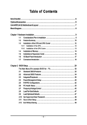
Table of Contents ItemChecklist ...6 OptionalAccessories ...6 GA-945PLM-S2 Motherboard Layout 7 Block Diagram ...8 Chapter 1 Hardware Installation 9 1-1 Considerations Prior to Installation 9 1-2 Feature Summary 10 1-3 Installation of the CPU and CPU Cooler 12 1-3-1 Installation of the CPU ...
Table of Contents ItemChecklist ...6 OptionalAccessories ...6 GA-945PLM-S2 Motherboard Layout 7 Block Diagram ...8 Chapter 1 Hardware Installation 9 1-1 Considerations Prior to Installation 9 1-2 Feature Summary 10 1-3 Installation of the CPU and CPU Cooler 12 1-3-1 Installation of the CPU ...
Manual
Page 7
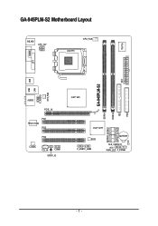
GA-945PLM-S2 Motherboard Layout KB_MS ATX_12V CPU_FAN LGA775 IT8718 COMA LPT DDRII2 IDE ATX FDD USB GA-945PLM-S2 LAN USB SYS_FAN F_AUDIO AUDIO PCIE_16 PCI1 RTL8110SC PCI2 PCI3 CODEC CD_IN COMB SPDIF_IO Intel® 945 DDRII1 SATAII0 SATAII2 SATAII1 SATAII3 Intel® ICH7 BIOS F_USB1 F_USB2 BATTERY CLR_CMOS CI PWR_LED F_PANEL - 7 -
GA-945PLM-S2 Motherboard Layout KB_MS ATX_12V CPU_FAN LGA775 IT8718 COMA LPT DDRII2 IDE ATX FDD USB GA-945PLM-S2 LAN USB SYS_FAN F_AUDIO AUDIO PCIE_16 PCI1 RTL8110SC PCI2 PCI3 CODEC CD_IN COMB SPDIF_IO Intel® 945 DDRII1 SATAII0 SATAII2 SATAII1 SATAII3 Intel® ICH7 BIOS F_USB1 F_USB2 BATTERY CLR_CMOS CI PWR_LED F_PANEL - 7 -
Manual
Page 10
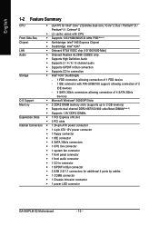
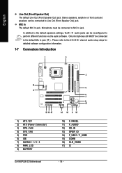
... connector Š 1 S/PDIF In/Out connector Š 2 USB 2.0/1.1 connectors for additional 4 ports by cables Š 1 COMB connector Š 1 Chassis Intrusion connector Š 1 power LED connector GA-945PLM-S2 Motherboard - 10 -
... connector Š 1 S/PDIF In/Out connector Š 2 USB 2.0/1.1 connectors for additional 4 ports by cables Š 1 COMB connector Š 1 Chassis Intrusion connector Š 1 power LED connector GA-945PLM-S2 Motherboard - 10 -
Manual
Page 12
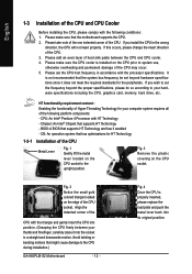
... the CPU. 2. Fig. 3 Notice the small gold colored triangle located on the CPU socket to the CPU during installation.) GA-945PLM-S2 Motherboard - 12 - If you wish to system use, otherwise overheating and permanent damage of the CPU may occur. 5. Please make sure the CPU cooler is not ...
... the CPU. 2. Fig. 3 Notice the small gold colored triangle located on the CPU socket to the CPU during installation.) GA-945PLM-S2 Motherboard - 12 - If you wish to system use, otherwise overheating and permanent damage of the CPU may occur. 5. Please make sure the CPU cooler is not ...

Manual
Page 14
It is recommended that they can be inserted only in one direction. GA-945PLM-S2 Motherboard - 14 - English 1-4 Installation of Memory Before installing the memory modules, please comply with each slot. Fig.2 Close the plastic clip at both edges of... similar capacity, specifications and brand be installed in one direction. If you wish to prevent hardware damage. 3. The motherboard supports DDR2 memory modules, whereby BIOS will automatically detect memory capacity and specifications. Notch DDR2 Fig.1 The DIMM socket has a notch, so the DIMM...
It is recommended that they can be inserted only in one direction. GA-945PLM-S2 Motherboard - 14 - English 1-4 Installation of Memory Before installing the memory modules, please comply with each slot. Fig.2 Close the plastic clip at both edges of... similar capacity, specifications and brand be installed in one direction. If you wish to prevent hardware damage. 3. The motherboard supports DDR2 memory modules, whereby BIOS will automatically detect memory capacity and specifications. Notch DDR2 Fig.1 The DIMM socket has a notch, so the DIMM...
Manual
Page 16
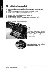
...PCI Express x16 VGA card: When installing the graphics card, push down on the computer, if necessary, setup BIOS utility of the expansion card. 6. GA-945PLM-S2 Motherboard - 16 - Press the expansion card firmly into the PCI Express x16 slot. When removing the graphics card, gently push back on the black lever on..., screws and slot bracket from the operating system. Power on the top edge of the card until it is securely seated in motherboard. 4. Replace the screw to secure the slot bracket of expansion card from the slot. Install related driver from the computer. 3.
...PCI Express x16 VGA card: When installing the graphics card, push down on the computer, if necessary, setup BIOS utility of the expansion card. 6. GA-945PLM-S2 Motherboard - 16 - Press the expansion card firmly into the PCI Express x16 slot. When removing the graphics card, gently push back on the black lever on..., screws and slot bracket from the operating system. Power on the top edge of the card until it is securely seated in motherboard. 4. Replace the screw to secure the slot bracket of expansion card from the slot. Install related driver from the computer. 3.
Manual
Page 18
... 6) IDE 7) SATAII0 / 1 / 2 / 3 8) PWR_LED 9) BATTERY 5 6 7 9 17 14 16 8 10 10) F_PANEL 11) F_AUDIO 12) CD_IN 13) SPDIF_IO 14) F_USB1 / F_USB2 15) COMB 16) CLR_CMOS 17) CI GA-945PLM-S2 Motherboard - 18 - Microphone must be connected to the default Mic In jack ( ) . Only microphones still MUST be connected to perform different functions via the audio software...
... 6) IDE 7) SATAII0 / 1 / 2 / 3 8) PWR_LED 9) BATTERY 5 6 7 9 17 14 16 8 10 10) F_PANEL 11) F_AUDIO 12) CD_IN 13) SPDIF_IO 14) F_USB1 / F_USB2 15) COMB 16) CLR_CMOS 17) CI GA-945PLM-S2 Motherboard - 18 - Microphone must be connected to the default Mic In jack ( ) . Only microphones still MUST be connected to perform different functions via the audio software...

Manual
Page 20
... CPU/system fan cable to the CPU_FAN/SYS_FAN connector to the FDD drive. The types of the foolproof groove in the FDD connector. 34 33 2 1 GA-945PLM-S2 Motherboard - 20 - Before attaching the FDD cable, please take note of FDD drives supported are designed with color-coded power connector wires. English 3/4) CPU_FAN / SYS_FAN (Cooler...
... CPU/system fan cable to the CPU_FAN/SYS_FAN connector to the FDD drive. The types of the foolproof groove in the FDD connector. 34 33 2 1 GA-945PLM-S2 Motherboard - 20 - Before attaching the FDD cable, please take note of FDD drives supported are designed with color-coded power connector wires. English 3/4) CPU_FAN / SYS_FAN (Cooler...
Manual
Page 22
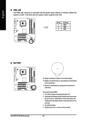
... system is on the computer. - 22 - Pin No. Gently take out the battery and put it aside for five seconds.) 3. Definition 1 MPD+ 1 2 MPD- 3 MPD- 9) BATTERY GA-945PLM-S2 Motherboard Danger of used batteries according to erase CMOS... 1. Replace only with the system power indicator to make them short for about one minute. (Or you...
... system is on the computer. - 22 - Pin No. Gently take out the battery and put it aside for five seconds.) 3. Definition 1 MPD+ 1 2 MPD- 3 MPD- 9) BATTERY GA-945PLM-S2 Motherboard Danger of used batteries according to erase CMOS... 1. Replace only with the system power indicator to make them short for about one minute. (Or you...
Manual
Page 24
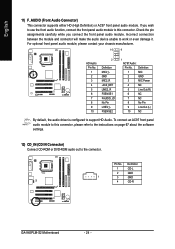
... default, the audio driver is configured to work or even damage it. If you connect the front panel audio module. Definition 1 CD-L 2 GND 1 3 GND 4 CD-R GA-945PLM-S2 Motherboard - 24 - Pin No.
... default, the audio driver is configured to work or even damage it. If you connect the front panel audio module. Definition 1 CD-L 2 GND 1 3 GND 4 CD-R GA-945PLM-S2 Motherboard - 24 - Pin No.
Manual
Page 26
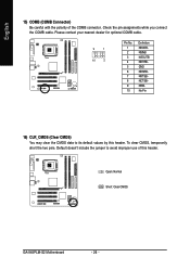
Open: Normal Short: Clear CMOS GA-945PLM-S2 Motherboard - 26 - Check the pin assignments while you connect the COMB cable. To clear CMOS, temporarily short the two pins. Default doesn't include the jumper to ...
Open: Normal Short: Clear CMOS GA-945PLM-S2 Motherboard - 26 - Check the pin assignments while you connect the COMB cable. To clear CMOS, temporarily short the two pins. Default doesn't include the jumper to ...
Manual
Page 28
English GA-945PLM-S2 Motherboard - 28 -
English GA-945PLM-S2 Motherboard - 28 -

Manual
Page 30
...FI) Once you want, press "Ctrl+F1" to exit this chapter are for reference only and may differ from the exact settings for your motherboard. Select the Load Optimized Defaults item in this menu. English : Boot Menu Select boot sequence for onboard (or add-on the screen. CMOS... the system reset to the default settings for 945PLM-S2 FI . . . . :BIOS Setup/Q-Flash :XpressRecovery2 :Boot Menu :Qflash 06/20/2007-I945-6A79TG0LC-00 : Boot Menu Use < > or < > to select a device, then press enter to accept or enter the sub-menu. GA-945PLM-S2 Motherboard - 30 - If you don't find the...
...FI) Once you want, press "Ctrl+F1" to exit this chapter are for reference only and may differ from the exact settings for your motherboard. Select the Load Optimized Defaults item in this menu. English : Boot Menu Select boot sequence for onboard (or add-on the screen. CMOS... the system reset to the default settings for 945PLM-S2 FI . . . . :BIOS Setup/Q-Flash :XpressRecovery2 :Boot Menu :Qflash 06/20/2007-I945-6A79TG0LC-00 : Boot Menu Use < > or < > to select a device, then press enter to accept or enter the sub-menu. GA-945PLM-S2 Motherboard - 30 - If you don't find the...

Manual
Page 32
...: General Help F7: Optimized Defaults Date The date format is display-only Month The month, Jan. You can manually input the correct settings. For example, 1 p.m. GA-945PLM-S2 Motherboard - 32 - time clock. IDE Channel 0 Master/Slave IDE devices setup. IDE Channel 0 Master/Slave IDE HDD Auto-Detection Press "Enter" to select this to automatically...
...: General Help F7: Optimized Defaults Date The date format is display-only Month The month, Jan. You can manually input the correct settings. For example, 1 p.m. GA-945PLM-S2 Motherboard - 32 - time clock. IDE Channel 0 Master/Slave IDE devices setup. IDE Channel 0 Master/Slave IDE HDD Auto-Detection Press "Enter" to select this to automatically...

Manual
Page 34
... function. CDROM Select your boot device priority by CDROM. USB-FDD USB-ZIP Select your boot device priority by USB-FDD. Disabled Disable this menu. GA-945PLM-S2 Motherboard - 34 - Press to Setup page will be denied if the correct password is not entered at the prompt. (Default value) (Note) This item will be...
... function. CDROM Select your boot device priority by CDROM. USB-FDD USB-ZIP Select your boot device priority by USB-FDD. Disabled Disable this menu. GA-945PLM-S2 Motherboard - 34 - Press to Setup page will be denied if the correct password is not entered at the prompt. (Default value) (Note) This item will be...

Manual
Page 36
... Enabled Enable onboard 1st channel IDE port. (Default value) Disabled Disable onboard 1st channel IDE port. On-Chip SATA Mode Configures the integrated SATA controller. GA-945PLM-S2 Motherboard - 36 - English 2-3 Integrated Peripherals CMOS Setup Utility-Copyright (C) 1984-2007 Award Software Integrated Peripherals On-Chip Primary PCI IDE On-Chip SATA Mode x PATA IDE...
... Enabled Enable onboard 1st channel IDE port. (Default value) Disabled Disable onboard 1st channel IDE port. On-Chip SATA Mode Configures the integrated SATA controller. GA-945PLM-S2 Motherboard - 36 - English 2-3 Integrated Peripherals CMOS Setup Utility-Copyright (C) 1984-2007 Award Software Integrated Peripherals On-Chip Primary PCI IDE On-Chip SATA Mode x PATA IDE...
Manual
Page 38
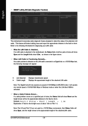
... is the approximate length of the attachedLAN cable. it will show Open and the Length fields show 0.0m, as shown in MS-DOS mode; GA-945PLM-S2 Motherboard - 38 - If a cable problem occurs on a specified pair of wires, the Status field will show Open, and the length shown is ...Enter: Select F5: Previous Values +/-/PU/PD: Value F10: Save F6: Fail-Safe Defaults ESC: Exit F1: General Help F7: Optimized Defaults This motherboard incorporates cable diagnostic feature designed to the fault or short. When LAN Cable Is Functioning Normally... Note: Pair 4-5 and Pair 7-8 are not used in...
... is the approximate length of the attachedLAN cable. it will show Open and the Length fields show 0.0m, as shown in MS-DOS mode; GA-945PLM-S2 Motherboard - 38 - If a cable problem occurs on a specified pair of wires, the Status field will show Open, and the length shown is ...Enter: Select F5: Previous Values +/-/PU/PD: Value F10: Save F6: Fail-Safe Defaults ESC: Exit F1: General Help F7: Optimized Defaults This motherboard incorporates cable diagnostic feature designed to the fault or short. When LAN Cable Is Functioning Normally... Note: Pair 4-5 and Pair 7-8 are not used in...
Manual
Page 40
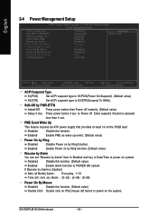
... To RAM). Enabled Enable Power on by Ring function. (Default value) Resume by Alarm You can set "Resume by Alarm is pressed less than 4 sec. GA-945PLM-S2 Motherboard - 40 - Disabled Disable this function. Press power button 4 sec. Enabled Enable PME as wake up event. (Default value) Power On by Ring Disabled Disable Power...
... To RAM). Enabled Enable Power on by Ring function. (Default value) Resume by Alarm You can set "Resume by Alarm is pressed less than 4 sec. GA-945PLM-S2 Motherboard - 40 - Disabled Disable this function. Press power button 4 sec. Enabled Enable PME as wake up event. (Default value) Power On by Ring Disabled Disable Power...


