
Manual
Page 5
Channel Audio Function Introduction 62 4-2 Troubleshooting 68 - 5 - Chapter 3 Install Drivers 51 3-1 Install Chipset Drivers 51 3-2 SoftwareApplications 52 3-3 Driver CD Information 52 3-4 Hardware Information 53 3-5 Contact Us ...53 Chapter 4 Appendix 55 4-1 Unique Software Utilities 55 4-1-1 EasyTune 5 Introduction 55 4-1-2 Xpress Recovery2 Introduction 56 4-1-3 Flash BIOS Method Introduction 58 4-1-4 2- / 4- / 6- / 8-
Channel Audio Function Introduction 62 4-2 Troubleshooting 68 - 5 - Chapter 3 Install Drivers 51 3-1 Install Chipset Drivers 51 3-2 SoftwareApplications 52 3-3 Driver CD Information 52 3-4 Hardware Information 53 3-5 Contact Us ...53 Chapter 4 Appendix 55 4-1 Unique Software Utilities 55 4-1-1 EasyTune 5 Introduction 55 4-1-2 Xpress Recovery2 Introduction 56 4-1-3 Flash BIOS Method Introduction 58 4-1-4 2- / 4- / 6- / 8-
Manual
Page 7
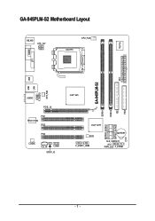
GA-945PLM-S2 Motherboard Layout KB_MS ATX_12V CPU_FAN LGA775 IT8718 COMA LPT DDRII2 IDE ATX FDD USB GA-945PLM-S2 LAN USB SYS_FAN F_AUDIO AUDIO PCIE_16 PCI1 RTL8110SC PCI2 PCI3 CODEC CD_IN COMB SPDIF_IO Intel® 945 DDRII1 SATAII0 SATAII2 SATAII1 SATAII3 Intel® ICH7 BIOS F_USB1 F_USB2 BATTERY CLR_CMOS CI PWR_LED F_PANEL - 7 -
GA-945PLM-S2 Motherboard Layout KB_MS ATX_12V CPU_FAN LGA775 IT8718 COMA LPT DDRII2 IDE ATX FDD USB GA-945PLM-S2 LAN USB SYS_FAN F_AUDIO AUDIO PCIE_16 PCI1 RTL8110SC PCI2 PCI3 CODEC CD_IN COMB SPDIF_IO Intel® 945 DDRII1 SATAII0 SATAII2 SATAII1 SATAII3 Intel® ICH7 BIOS F_USB1 F_USB2 BATTERY CLR_CMOS CI PWR_LED F_PANEL - 7 -
Manual
Page 10
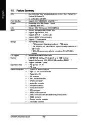
...Intel® ICH7 LAN Š Onboard RTL8110SC chip (10/100/1000 Mbit) Audio Š Onboard Realtek ALC888 CODEC chip Š Supports High Definition Audio Š Supports 2 / 4 / 6 / 8 channel audio Š Supports S/PDIF In/Out connection Š Supports CD In connection ... Š 1 front panel connector Š 1 front audio connector Š 1 CD In connector Š 1 S/PDIF In/Out connector Š 2 USB 2.0/1.1 connectors for additional 4 ports by cables Š 1 COMB connector Š 1 Chassis Intrusion connector Š 1 power LED connector GA-945PLM-S2 Motherboard - 10 -
...Intel® ICH7 LAN Š Onboard RTL8110SC chip (10/100/1000 Mbit) Audio Š Onboard Realtek ALC888 CODEC chip Š Supports High Definition Audio Š Supports 2 / 4 / 6 / 8 channel audio Š Supports S/PDIF In/Out connection Š Supports CD In connection ... Š 1 front panel connector Š 1 front audio connector Š 1 CD In connector Š 1 S/PDIF In/Out connector Š 2 USB 2.0/1.1 connectors for additional 4 ports by cables Š 1 COMB connector Š 1 Chassis Intrusion connector Š 1 power LED connector GA-945PLM-S2 Motherboard - 10 -
Manual
Page 11
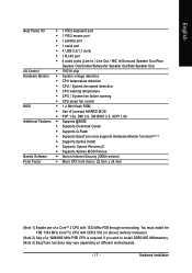
... English Rear Panel I/O Š 1 PS/2 keyboard port Š 1 PS/2 mouse port Š 1 parallel port Š 1 serial port Š 4 USB 2.0/1.1 ports Š 1 RJ-45 port Š 6 audio jacks (Line In / Line Out / MIC In/Surround Speaker Out (Rear Speaker Out)/Center/Subwoofer Speaker Out/Side Speaker Out) I/O Control Š IT8718 chip Hardware...
... English Rear Panel I/O Š 1 PS/2 keyboard port Š 1 PS/2 mouse port Š 1 parallel port Š 1 serial port Š 4 USB 2.0/1.1 ports Š 1 RJ-45 port Š 6 audio jacks (Line In / Line Out / MIC In/Surround Speaker Out (Rear Speaker Out)/Center/Subwoofer Speaker Out/Side Speaker Out) I/O Control Š IT8718 chip Hardware...
Manual
Page 18
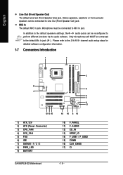
... 13) SPDIF_IO 14) F_USB1 / F_USB2 15) COMB 16) CLR_CMOS 17) CI GA-945PLM-S2 Motherboard - 18 - MIC In The default MIC In jack. Microphone must be connected to Line Out (Front Speaker Out) jack. In addition to the default speakers settings, the ~ audio jacks can be reconfigured to the 2-/4-/6-/8- English Line Out (Front Speaker...
... 13) SPDIF_IO 14) F_USB1 / F_USB2 15) COMB 16) CLR_CMOS 17) CI GA-945PLM-S2 Motherboard - 18 - MIC In The default MIC In jack. Microphone must be connected to Line Out (Front Speaker Out) jack. In addition to the default speakers settings, the ~ audio jacks can be reconfigured to the 2-/4-/6-/8- English Line Out (Front Speaker...
Manual
Page 24
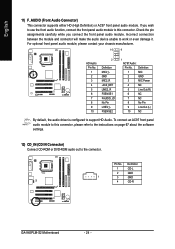
... 7 8 9 10 2 Definition MIC2_L GND MIC2_R -ACZ_DET LINE2_R FSENSE1 FAUDIO_JD No Pin LINE2_L FSENSE2 1 AC'97 Audio: Pin No. Incorrect connection between the module and connector will make the audio device unable to support HD Audio. Definition 1 MIC 2 GND 3 MIC Power 4 NC 5 Line Out (R) 6 NC 7 NC 8 No ...(CD IN Connector) Connect CD-ROM or DVD-ROM audio out to this connector. If you connect the front panel audio module. To connect an AC97 front panel audio module to the connector. Definition 1 CD-L 2 GND 1 3 GND 4 CD-R GA-945PLM-S2 Motherboard - 24 -
... 7 8 9 10 2 Definition MIC2_L GND MIC2_R -ACZ_DET LINE2_R FSENSE1 FAUDIO_JD No Pin LINE2_L FSENSE2 1 AC'97 Audio: Pin No. Incorrect connection between the module and connector will make the audio device unable to support HD Audio. Definition 1 MIC 2 GND 3 MIC Power 4 NC 5 Line Out (R) 6 NC 7 NC 8 No ...(CD IN Connector) Connect CD-ROM or DVD-ROM audio out to this connector. If you connect the front panel audio module. To connect an AC97 front panel audio module to the connector. Definition 1 CD-L 2 GND 1 3 GND 4 CD-R GA-945PLM-S2 Motherboard - 24 -

Manual
Page 25
.... 5 1 6 2 Pin No. 1 2 3 4 5 6 Definition Power No Pin SPDIF SPDIFI GND GND 14) F_ USB1 / F_USB2 (Front USB Connector) Be careful with the polarity of providing digital audio to external speakers or compressed AC3 data to work or even damage it . For optional S/PDIF cable, please contact your device has digital output function...
.... 5 1 6 2 Pin No. 1 2 3 4 5 6 Definition Power No Pin SPDIF SPDIFI GND GND 14) F_ USB1 / F_USB2 (Front USB Connector) Be careful with the polarity of providing digital audio to external speakers or compressed AC3 data to work or even damage it . For optional S/PDIF cable, please contact your device has digital output function...

Manual
Page 37
... controller. USB 2.0 Controller You can disable this function if you are not using onboard USB 2.0 feature. Azalia Codec Auto Auto detect Azalia audio function. (Default value) Disabled Disable Azalia audio function. Disable USB mouse support. (Default value) Legacy USB storage detect This option allows users to decide whether to detect USB storage...
... controller. USB 2.0 Controller You can disable this function if you are not using onboard USB 2.0 feature. Azalia Codec Auto Auto detect Azalia audio function. (Default value) Disabled Disable Azalia audio function. Disable USB mouse support. (Default value) Legacy USB storage detect This option allows users to decide whether to detect USB storage...

Manual
Page 62
... if the stereo output is applied. GA-945PLM-S2 Motherboard - 62 - STEP 1 : After installation of the audio driver, you should find an Audio Manager icon in your system tray (you use the speaker with amplifier to open the Audio Control Panel. Stereo Speakers Connection and Settings... change the center/ subwoofer speaker out jack to the right. The jack retasking capability supported by the audio software provided. English 4-1-4 2- / 4- / 6- / 8- Multi-channel audio experiences have become a reality so you can also find the icon in Windows XP) Center/Subwoofer Speaker...
... if the stereo output is applied. GA-945PLM-S2 Motherboard - 62 - STEP 1 : After installation of the audio driver, you should find an Audio Manager icon in your system tray (you use the speaker with amplifier to open the Audio Control Panel. Stereo Speakers Connection and Settings... change the center/ subwoofer speaker out jack to the right. The jack retasking capability supported by the audio software provided. English 4-1-4 2- / 4- / 6- / 8- Multi-channel audio experiences have become a reality so you can also find the icon in Windows XP) Center/Subwoofer Speaker...

Manual
Page 63
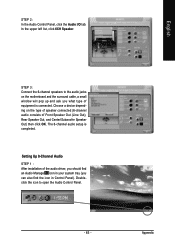
English STEP 2: In the Audio Control Panel, click the Audio I/O tab. Choose Headphone or Line Out depending on the device connected and click OK. Setting Up 4-Channel Audio STEP 1 : After installation of equipment is completed. Doubleclick the icon to the rear Line Out jack, a small window will pop up and ask ...you what type of the audio driver, you should find an Audio Manager icon in your system tray (you can also find the icon in Control Panel). STEP 3: Connect a speaker or headphone to ...
English STEP 2: In the Audio Control Panel, click the Audio I/O tab. Choose Headphone or Line Out depending on the device connected and click OK. Setting Up 4-Channel Audio STEP 1 : After installation of equipment is completed. Doubleclick the icon to the rear Line Out jack, a small window will pop up and ask ...you what type of the audio driver, you should find an Audio Manager icon in your system tray (you can also find the icon in Control Panel). STEP 3: Connect a speaker or headphone to ...

Manual
Page 64
... is connected. Doubleclick the icon to the audio jacks on the type of speaker connected (4-channel audio consists of equipment is completed. GA-945PLM-S2 Motherboard - 64 - STEP 3: Connect the 4-channel speakers to open the Audio Control Panel. In the upper left list, click 4CH Speaker. Choose a device depending on the motherboard and the surround cable...
... is connected. Doubleclick the icon to the audio jacks on the type of speaker connected (4-channel audio consists of equipment is completed. GA-945PLM-S2 Motherboard - 64 - STEP 3: Connect the 4-channel speakers to open the Audio Control Panel. In the upper left list, click 4CH Speaker. Choose a device depending on the motherboard and the surround cable...
Manual
Page 65
... of equipment is completed. In the upper left list, click 6CH Speaker. English STEP 2: In the Audio Control Panel, click the Audio I/O tab. Choose a device depending on the motherboard and the surround cable, a small window will pop up and ask you can also find the icon ...in Control Panel). Appendix The 6-channel audio setup is connected. Setting Up 8-Channel Audio STEP 1 : After installation of the audio driver, you should find an Audio Manager icon in your system tray (you what type of Front Speaker Out (Line Out), Rear ...
... of equipment is completed. In the upper left list, click 6CH Speaker. English STEP 2: In the Audio Control Panel, click the Audio I/O tab. Choose a device depending on the motherboard and the surround cable, a small window will pop up and ask you can also find the icon ...in Control Panel). Appendix The 6-channel audio setup is connected. Setting Up 8-Channel Audio STEP 1 : After installation of the audio driver, you should find an Audio Manager icon in your system tray (you what type of Front Speaker Out (Line Out), Rear ...

Manual
Page 66
... Out) then click OK. STEP 3: Connect the 8-channel speakers to the audio jacks on the type of speaker connected (8-channel audio consists of equipment is completed. Sound Effect Configuration: At the Sound Effect menu, users can adjust sound option settings as desired. GA-945PLM-S2 Motherboard - 66 - In the upper left list, click 8CH Speaker...
... Out) then click OK. STEP 3: Connect the 8-channel speakers to the audio jacks on the type of speaker connected (8-channel audio consists of equipment is completed. Sound Effect Configuration: At the Sound Effect menu, users can adjust sound option settings as desired. GA-945PLM-S2 Motherboard - 66 - In the upper left list, click 8CH Speaker...
Manual
Page 67
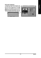
This action completes the AC'97 Audio configuration. - 67 - Appendix English AC'97 Audio Configuration: To enable the front panel audio connector to support AC97 Audio mode, go to the Audio Control Panel and click the Audio I/O tab. In the ANALOG area, click the Tool icon and then select the Disable front panel jack detection check box.
This action completes the AC'97 Audio configuration. - 67 - Appendix English AC'97 Audio Configuration: To enable the front panel audio connector to support AC97 Audio mode, go to the Audio Control Panel and click the Audio I/O tab. In the ANALOG area, click the Tool icon and then select the Disable front panel jack detection check box.


