Manual
Page 4
...1-3-1 Installation of the CPU 12 1-3-2 Installation of the CPU Cooler 13 1-4 Installation of Memory 14 1-5 Installation of Expansion Cards 16 1-6 I/O Back Panel Introduction 17 1-7 Connectors Introduction 18 Chapter 2 BIOS Setup 29 The Main Menu (For example: BIOS Ver. : FI 30 2-1 Standard CMOS Features 32 2-2 Advanced BIOS Features 34 2-3 IntegratedPeripherals 36 2-4 Power Management Setup 40 2-5 PnP/PCI Configurations 42 2-6 PC Health Status 43 2-7 Frequency/Voltage Control 45 2-8 Load Fail-Safe Defaults 47 2-9 Load Optimized Defaults 47 2-10 Set Supervisor/User Password 48...
...1-3-1 Installation of the CPU 12 1-3-2 Installation of the CPU Cooler 13 1-4 Installation of Memory 14 1-5 Installation of Expansion Cards 16 1-6 I/O Back Panel Introduction 17 1-7 Connectors Introduction 18 Chapter 2 BIOS Setup 29 The Main Menu (For example: BIOS Ver. : FI 30 2-1 Standard CMOS Features 32 2-2 Advanced BIOS Features 34 2-3 IntegratedPeripherals 36 2-4 Power Management Setup 40 2-5 PnP/PCI Configurations 42 2-6 PC Health Status 43 2-7 Frequency/Voltage Control 45 2-8 Load Fail-Safe Defaults 47 2-9 Load Optimized Defaults 47 2-10 Set Supervisor/User Password 48...
Manual
Page 10
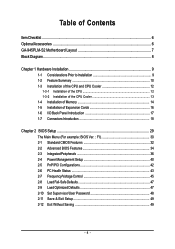
...; 1 PCI Express x16 slot Š 3 PCI slots Internal Connectors Š 1 24-pin ATX power connector Š 1 4-pin ATX 12V power connector Š 1 floppy connector Š 1 IDE connector Š 4 SATA 3Gb/s connectors Š 1 CPU fan connector Š 1 system fan connector Š 1 front panel connector Š 1 front audio connector Š 1 CD In connector Š 1 S/PDIF In/Out connector Š 2 USB 2.0/1.1 connectors for additional 4 ports by cables Š 1 COMB connector Š 1 Chassis Intrusion connector Š 1 power LED connector GA-945PLM-S2 Motherboard - 10...
...; 1 PCI Express x16 slot Š 3 PCI slots Internal Connectors Š 1 24-pin ATX power connector Š 1 4-pin ATX 12V power connector Š 1 floppy connector Š 1 IDE connector Š 4 SATA 3Gb/s connectors Š 1 CPU fan connector Š 1 system fan connector Š 1 front panel connector Š 1 front audio connector Š 1 CD In connector Š 1 S/PDIF In/Out connector Š 2 USB 2.0/1.1 connectors for additional 4 ports by cables Š 1 COMB connector Š 1 Chassis Intrusion connector Š 1 power LED connector GA-945PLM-S2 Motherboard - 10...
Manual
Page 13
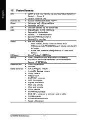
... detailed installation instructions, please refer to the CPU cooler installation section of the user manual) Fig. 5 Please check the back of motherboard after installing. Fig. 4 Please make sure the push pins aim to the CPU fan header located on the surface of the CPU cooler to the pin hole on the male push pin doesn't face inwards before installation. (This instruction is complete. Use extreme care when removing the CPU cooler...
... detailed installation instructions, please refer to the CPU cooler installation section of the user manual) Fig. 5 Please check the back of motherboard after installing. Fig. 4 Please make sure the push pins aim to the CPU fan header located on the surface of the CPU cooler to the pin hole on the male push pin doesn't face inwards before installation. (This instruction is complete. Use extreme care when removing the CPU cooler...

Manual
Page 15
Dual Channel mode cannot be used. - 15 - When enabling Dual Channel mode with two memory modules, it is installed. 2. Due to chipset limitation, read the following guidelines before installing the memory in Dual Channel mode. 1. Hardware Installation English Dual Channel Memory Configuration The GA-945PLM-S2 supports the Dual Channel Technology. After operating the Dual Channel Technology, the bandwidth of the same capacity, brand, speed, and chips be enabled if only one DDR2 memory module is recommended that memory of memory bus will double.
Dual Channel mode cannot be used. - 15 - When enabling Dual Channel mode with two memory modules, it is installed. 2. Due to chipset limitation, read the following guidelines before installing the memory in Dual Channel mode. 1. Hardware Installation English Dual Channel Memory Configuration The GA-945PLM-S2 supports the Dual Channel Technology. After operating the Dual Channel Technology, the bandwidth of the same capacity, brand, speed, and chips be enabled if only one DDR2 memory module is recommended that memory of memory bus will double.
Manual
Page 18
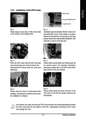
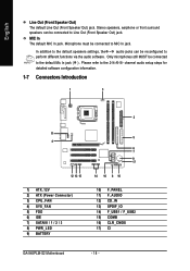
Microphone must be connected to the default Mic In jack ( ) . channel audio setup steps for detailed software configuration information. 1-7 Connectors Introduction 1 3 2 11 4 12 13 15 1) ATX_12V 2) ATX (Power Connector) 3) CPU_FAN 4) SYS_FAN 5) FDD 6) IDE 7) SATAII0 / 1 / 2 / 3 8) PWR_LED 9) BATTERY 5 6 7 9 17 14 16 8 10 10) F_PANEL 11) F_AUDIO 12) CD_IN 13) SPDIF_IO 14) F_USB1 / F_USB2 15) COMB 16) CLR_CMOS 17) CI GA-945PLM-S2 Motherboard - 18 - MIC In The default MIC In jack...
Microphone must be connected to the default Mic In jack ( ) . channel audio setup steps for detailed software configuration information. 1-7 Connectors Introduction 1 3 2 11 4 12 13 15 1) ATX_12V 2) ATX (Power Connector) 3) CPU_FAN 4) SYS_FAN 5) FDD 6) IDE 7) SATAII0 / 1 / 2 / 3 8) PWR_LED 9) BATTERY 5 6 7 9 17 14 16 8 10 10) F_PANEL 11) F_AUDIO 12) CD_IN 13) SPDIF_IO 14) F_USB1 / F_USB2 15) COMB 16) CLR_CMOS 17) CI GA-945PLM-S2 Motherboard - 18 - MIC In The default MIC In jack...

Manual
Page 20
... cable connects to prevent CPU damage or system hanging caused by overheating. 1 CPU_FAN CPU_FAN : Pin No. 1 2 3 4 Definition GND +12V / Speed Control Sense Speed Control 1 SYS_FAN SYS_FAN : Pin No. 1 2 3 Definition GND +12V Sense 5) FDD (Floppy Connector) The FDD connector is the ground wire (GND). The types of the foolproof groove in the FDD connector. 34 33 2 1 GA-945PLM-S2 Motherboard - 20 - English 3/4) CPU_FAN / SYS_FAN (Cooler Fan Power Connector) The cooler fan power connector supplies a +12V power voltage via a 3-pin/4-pin(CPU_FAN) power connector...
... cable connects to prevent CPU damage or system hanging caused by overheating. 1 CPU_FAN CPU_FAN : Pin No. 1 2 3 4 Definition GND +12V / Speed Control Sense Speed Control 1 SYS_FAN SYS_FAN : Pin No. 1 2 3 Definition GND +12V Sense 5) FDD (Floppy Connector) The FDD connector is the ground wire (GND). The types of the foolproof groove in the FDD connector. 34 33 2 1 GA-945PLM-S2 Motherboard - 20 - English 3/4) CPU_FAN / SYS_FAN (Cooler Fan Power Connector) The cooler fan power connector supplies a +12V power voltage via a 3-pin/4-pin(CPU_FAN) power connector...

Manual
Page 21
... Slave (for the SATA 3Gb/s and install the proper driver in the IDE connector. 40 39 2 1 7) SATAII0 / 1 / 2 / 3 (SATA 3Gb/s Connector, Controlled by ICH7) SATA 3Gb/s can then connect to two IDE devices (hard drive or optical drive). Please refer to the BIOS setting for information on the IDE device). If you wish to connect two IDE devices, please set the jumper on one IDE cable, and the single IDE cable can provide up to the instructions located on settings, please refer...
... Slave (for the SATA 3Gb/s and install the proper driver in the IDE connector. 40 39 2 1 7) SATAII0 / 1 / 2 / 3 (SATA 3Gb/s Connector, Controlled by ICH7) SATA 3Gb/s can then connect to two IDE devices (hard drive or optical drive). Please refer to the BIOS setting for information on the IDE device). If you wish to connect two IDE devices, please set the jumper on one IDE cable, and the single IDE cable can provide up to the instructions located on settings, please refer...
Manual
Page 24
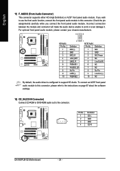
...-L 2 GND 1 3 GND 4 CD-R GA-945PLM-S2 Motherboard - 24 - Incorrect connection between the module and connector will make the audio device unable to support HD Audio. Pin No. If you connect the front panel audio module. To connect an AC97 front panel audio module to the connector. Definition 1 MIC 2 GND 3 MIC Power 4 NC 5 Line Out (R) 6 NC 7 NC 8 No Pin 9 Line Out (L) 10 NC By default, the audio driver is configured to work or even damage it...
...-L 2 GND 1 3 GND 4 CD-R GA-945PLM-S2 Motherboard - 24 - Incorrect connection between the module and connector will make the audio device unable to support HD Audio. Pin No. If you connect the front panel audio module. To connect an AC97 front panel audio module to the connector. Definition 1 MIC 2 GND 3 MIC Power 4 NC 5 Line Out (R) 6 NC 7 NC 8 No Pin 9 Line Out (L) 10 NC By default, the audio driver is configured to work or even damage it...

Manual
Page 30
... Setup ` PnP/PCI Configurations ` PC Health Status ` Frequency/Voltage Control ESC: Quit F8: Q-Flash Load Fail-Safe Defaults Load Optimized Defaults Set Supervisor Password Set User Password Save & Exit Setup Exit Without Saving KLJI: Select Item F10: Save & Exit Setup Time, Date, Hard Disk Type... 1. GA-945PLM-S2 Motherboard - 30 - The BIOS Setup menus described in the BIOS Setup when somehow the system is not stable as figure below) will appear on cards) device. Boot Menu == Select a Boot First device == Floppy LS120 Hard Disk CDROM ZIP USB-FDD USB-ZIP USB-CDROM USB-HDD LAN...
... Setup ` PnP/PCI Configurations ` PC Health Status ` Frequency/Voltage Control ESC: Quit F8: Q-Flash Load Fail-Safe Defaults Load Optimized Defaults Set Supervisor Password Set User Password Save & Exit Setup Exit Without Saving KLJI: Select Item F10: Save & Exit Setup Time, Date, Hard Disk Type... 1. GA-945PLM-S2 Motherboard - 30 - The BIOS Setup menus described in the BIOS Setup when somehow the system is not stable as figure below) will appear on cards) device. Boot Menu == Select a Boot First device == Floppy LS120 Hard Disk CDROM ZIP USB-FDD USB-ZIP USB-CDROM USB-HDD LAN...

Manual
Page 32
...] Drive A Floppy 3 Mode Support [1.44M, 3.5"] [Disabled] Halt On [All, But Keyboard] Base Memory Extended Memory 640K 239M KLJI: Move Enter: Select F5: Previous Values +/-/PU/PD: Value F10: Save F6: Fail-Safe Defaults ESC: Exit F1: General Help F7: Optimized Defaults Date The date format is calculated base on the 24-hour military- You can use one of currectly installed hard drive. time clock. For example, 1 p.m. GA-945PLM-S2 Motherboard - 32 - Access Mode Use...
...] Drive A Floppy 3 Mode Support [1.44M, 3.5"] [Disabled] Halt On [All, But Keyboard] Base Memory Extended Memory 640K 239M KLJI: Move Enter: Select F5: Previous Values +/-/PU/PD: Value F10: Save F6: Fail-Safe Defaults ESC: Exit F1: General Help F7: Optimized Defaults Date The date format is calculated base on the 24-hour military- You can use one of currectly installed hard drive. time clock. For example, 1 p.m. GA-945PLM-S2 Motherboard - 32 - Access Mode Use...

Manual
Page 36
...Combined Sets all SATA devices to operate in PATA mode. PATA IDE Set to Ch.0 Master/Slave Set PATA IDE to Ch. 0 Master/Slave. (Default value) Ch.1 Master/Slave Set PATA IDE to USB Controller USB 2.0 Controller USB Keyboard Support USB Mouse Support Legacy USB storage detect Azalia Codec Onboard H/W LAN ` SMART LAN Onboard LAN Boot ROM Onboard Serial Port 1 Onboard Serial Port 2 Onboard Parallel Port Parallel Port Mode x ECP Mode Use DMA [Enabled] [Auto] Ch.0 Master/Slave Ch.2 Master/Slave Ch.3 Master/Slave [Enabled] [Enabled] [Disabled] [Disabled] [Enabled] [Auto] [Enabled] [Press Enter...
...Combined Sets all SATA devices to operate in PATA mode. PATA IDE Set to Ch.0 Master/Slave Set PATA IDE to Ch. 0 Master/Slave. (Default value) Ch.1 Master/Slave Set PATA IDE to USB Controller USB 2.0 Controller USB Keyboard Support USB Mouse Support Legacy USB storage detect Azalia Codec Onboard H/W LAN ` SMART LAN Onboard LAN Boot ROM Onboard Serial Port 1 Onboard Serial Port 2 Onboard Parallel Port Parallel Port Mode x ECP Mode Use DMA [Enabled] [Auto] Ch.0 Master/Slave Ch.2 Master/Slave Ch.3 Master/Slave [Enabled] [Enabled] [Disabled] [Disabled] [Enabled] [Auto] [Enabled] [Press Enter...

Manual
Page 37
...Enable USB 2.0 controller. (Default value) Disable USB 2.0 controller. Disabled Disable USB keyboard support. (Default value) USB Mouse Support Enabled Disabled Enable USB mouse support. Azalia Codec Auto Auto detect Azalia audio function. (Default value) Disabled Disable Azalia audio function. Disable USB mouse support. (Default value) Legacy USB storage detect This option allows users to decide whether to detect USB storage devices, including USB flash drives and USB hard drives during POST. USB 2.0 Controller You can disable this function if you are not using onboard...
...Enable USB 2.0 controller. (Default value) Disable USB 2.0 controller. Disabled Disable USB keyboard support. (Default value) USB Mouse Support Enabled Disabled Enable USB mouse support. Azalia Codec Auto Auto detect Azalia audio function. (Default value) Disabled Disable Azalia audio function. Disable USB mouse support. (Default value) Legacy USB storage detect This option allows users to decide whether to detect USB storage devices, including USB flash drives and USB hard drives during POST. USB 2.0 Controller You can disable this function if you are not using onboard...
Manual
Page 44
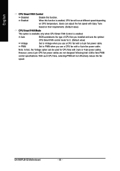
.... (Default value) CPU Smart FAN Mode This option is available only when CPU Smart FAN Control is enabled. However, some 4-pin CPU fan power cables are not designed following Intel 4-Wire fans PWM control specifications. GA-945PLM-S2 Motherboard - 44 - Auto BIOS autodetects the type of CPU fan you installed and sets the optimal CPU Smart FAN control mode for CPU fans with Easy Tune based on CPU temperature. PWM Set to Voltage when you use a CPU fan with a 4-pin fan power cable. English CPU Smart FAN Control Disabled Disable this function is enabled, CPU fan will...
.... (Default value) CPU Smart FAN Mode This option is available only when CPU Smart FAN Control is enabled. However, some 4-pin CPU fan power cables are not designed following Intel 4-Wire fans PWM control specifications. GA-945PLM-S2 Motherboard - 44 - Auto BIOS autodetects the type of CPU fan you installed and sets the optimal CPU Smart FAN control mode for CPU fans with Easy Tune based on CPU temperature. PWM Set to Voltage when you use a CPU fan with a 4-pin fan power cable. English CPU Smart FAN Control Disabled Disable this function is enabled, CPU fan will...

Manual
Page 45
... Control CMOS Setup Utility-Copyright (C) 1984-2007 Award Software Frequency/Voltage Control CPU Clock Ratio (Note) O.C FSB1333 Core. 2 CPU CPU Host Clock Control x CPU Host Frequency(Mhz) x PCI Express Frequency(Mhz) System Memory Multiplier Memory Frequency (Mhz) [25X] [Disabled] [Disabled] 200 Auto [Auto] 667 Item Help Menu Level` KLJI: Move Enter: Select F5: Previous Values +/-/PU/PD: Value F10: Save F6: Fail-Safe Defaults ESC: Exit F1: General Help F7: Optimized Defaults Incorrectly using these features may result in system instability or corruption. for power users...
... Control CMOS Setup Utility-Copyright (C) 1984-2007 Award Software Frequency/Voltage Control CPU Clock Ratio (Note) O.C FSB1333 Core. 2 CPU CPU Host Clock Control x CPU Host Frequency(Mhz) x PCI Express Frequency(Mhz) System Memory Multiplier Memory Frequency (Mhz) [25X] [Disabled] [Disabled] 200 Auto [Auto] 667 Item Help Menu Level` KLJI: Move Enter: Select F5: Previous Values +/-/PU/PD: Value F10: Save F6: Fail-Safe Defaults ESC: Exit F1: General Help F7: Optimized Defaults Incorrectly using these features may result in system instability or corruption. for power users...

Manual
Page 48
...in Advance BIOS Features Menu, you can enter Setup freely. GA-945PLM-S2 Motherboard - 48 - When disabled, anyone may also press to abort the selection and not enter a password. English 2-10 Set Supervisor/User Password CMOS Setup Utility-Copyright (C) 1984-2007 Award Software ` Standard CMOS Features ` Advanced BIOS Features ` Integrated Peripherals ` Power Management Setup ` PnP/PCI ConfiguratioEnsnter Password: ` PC Health Status ` Frequency/Voltage Control Load Fail-Safe Defaults Load Optimized Defaults Set Supervisor Password Set User Password Save & Exit Setup Exit Without...
...in Advance BIOS Features Menu, you can enter Setup freely. GA-945PLM-S2 Motherboard - 48 - When disabled, anyone may also press to abort the selection and not enter a password. English 2-10 Set Supervisor/User Password CMOS Setup Utility-Copyright (C) 1984-2007 Award Software ` Standard CMOS Features ` Advanced BIOS Features ` Integrated Peripherals ` Power Management Setup ` PnP/PCI ConfiguratioEnsnter Password: ` PC Health Status ` Frequency/Voltage Control Load Fail-Safe Defaults Load Optimized Defaults Set Supervisor Password Set User Password Save & Exit Setup Exit Without...

Manual
Page 51
... do so may affect the driver installation. • Some device drivers will auto start and show the installation guide. If not, please double click the CD-ROM device icon in the motherboard driver disk. • For USB 2.0 driver support under the Windows XP operating system, please install the Windows XP Service Pack 1 or later. Please pick the item that came with your motherboard into your CD-ROM drive, the driver CD-title will restart...
... do so may affect the driver installation. • Some device drivers will auto start and show the installation guide. If not, please double click the CD-ROM device icon in the motherboard driver disk. • For USB 2.0 driver support under the Windows XP operating system, please install the Windows XP Service Pack 1 or later. Please pick the item that came with your motherboard into your CD-ROM drive, the driver CD-title will restart...

Manual
Page 56
... will stay permanent in the future. 2. GA-945PLM-S2 Motherboard - 56 - English 4-1-2 Xpress Recovery2 Introduction Xpress Recovery2 is able to back up data on hard disks on . . . Boot from the CD-ROM, you can enter Xpress Recovery2 by pressing the key in your CD-ROM drive. Save the settings and exit the BIOS Setup. Supporting Microsoft operating systems including Windows XP/2000/NT/98/Me and DOS...
... will stay permanent in the future. 2. GA-945PLM-S2 Motherboard - 56 - English 4-1-2 Xpress Recovery2 Introduction Xpress Recovery2 is able to back up data on hard disks on . . . Boot from the CD-ROM, you can enter Xpress Recovery2 by pressing the key in your CD-ROM drive. Save the settings and exit the BIOS Setup. Supporting Microsoft operating systems including Windows XP/2000/NT/98/Me and DOS...
Manual
Page 58
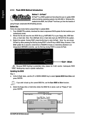
... ESC:Reset :Power Off Total size : 0 GA-945PLM-S2 Motherboard Free size : 0 - 58 - Award Modular BIOS v6.00PG, An Energy Star Ally Copyright (C) 1984-2007, Award Software, Inc. Q-Flash Utility v2.02 Flash Type/Size SST 25VF040B 512K EnteFr l:oRppuyn A HDD 0-0 Keep DMI Data Enable Update BIOS from Drive and press ENTER. Updating the BIOS Step 1: a. In the Q-Flash menu, use the Save BIOS to access Q-Flash. Before Use: Follow the steps below before using Q-Flash to enter Q-Flash. Note: The USB flash drive or hard disk must use the End key during POST to Drive...
... ESC:Reset :Power Off Total size : 0 GA-945PLM-S2 Motherboard Free size : 0 - 58 - Award Modular BIOS v6.00PG, An Energy Star Ally Copyright (C) 1984-2007, Award Software, Inc. Q-Flash Utility v2.02 Flash Type/Size SST 25VF040B 512K EnteFr l:oRppuyn A HDD 0-0 Keep DMI Data Enable Update BIOS from Drive and press ENTER. Updating the BIOS Step 1: a. In the Q-Flash menu, use the Save BIOS to access Q-Flash. Before Use: Follow the steps below before using Q-Flash to enter Q-Flash. Note: The USB flash drive or hard disk must use the End key during POST to Drive...
Manual
Page 60
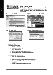
.... GA-945PLM-S2 Motherboard - 60 - Installation Complete and Run @BIOS Click Start/ Programs/ Gigabyte/ BIOS/ @BIOS Select @BIOS item than click Install Fig 3. Update BIOS through Internet: a. System will automatically download and update the BIOS. Please select "All Files" in dialog box while opening the old file. Installing the @BIOS utility Fig 2. Select the desired @BIOS server 1. Update BIOS NOT through Internet a. Fig 1. Do not click "Internet Update" icon b. Just select the desired @BIOS server to update their BIOS...
.... GA-945PLM-S2 Motherboard - 60 - Installation Complete and Run @BIOS Click Start/ Programs/ Gigabyte/ BIOS/ @BIOS Select @BIOS item than click Install Fig 3. Update BIOS through Internet: a. System will automatically download and update the BIOS. Please select "All Files" in dialog box while opening the old file. Installing the @BIOS utility Fig 2. Select the desired @BIOS server 1. Update BIOS NOT through Internet a. Fig 1. Do not click "Internet Update" icon b. Just select the desired @BIOS server to update their BIOS...
Manual
Page 68
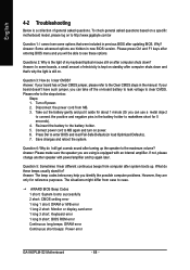
...). 4. AWARD BIOS Beep Codes 1 short: System boots successfully 2 short: CMOS setting error 1 long 1 short: DRAM or M/B error 1 long 2 short: Monitor or display card error 1 long 3 short: Keyboard error 1 long 9 short: BIOS ROM error Continuous long beeps: DRAM error Continuous short beeps: Power error GA-945PLM-S2 Motherboard - 68 - Re-insert the battery to see some boards, a small amount of general asked questions based on a specific motherboard model, please log on -board battery to leak voltage to the Clear CMOS steps in new BIOS version. English 4-2 Troubleshooting Below is...
...). 4. AWARD BIOS Beep Codes 1 short: System boots successfully 2 short: CMOS setting error 1 long 1 short: DRAM or M/B error 1 long 2 short: Monitor or display card error 1 long 3 short: Keyboard error 1 long 9 short: BIOS ROM error Continuous long beeps: DRAM error Continuous short beeps: Power error GA-945PLM-S2 Motherboard - 68 - Re-insert the battery to see some boards, a small amount of general asked questions based on a specific motherboard model, please log on -board battery to leak voltage to the Clear CMOS steps in new BIOS version. English 4-2 Troubleshooting Below is...


