Manual
Page 1
GA-945PLM-S2 Intel® CoreTM 2 Extreme dual-core / CoreTM 2 Duo / Intel® Pentium® D / Pentium® 4 / Celeron® D LGA775 Processor Motherboard User's Manual Rev. 6602 12ME-945PLM2R-6602R * The WEEE marking on the product indicates this product must not be disposed of with user's other household waste and must be handed over to a designated collection point for the recycling of waste electrical and electronic equipment!! * The WEEE marking applies only in European Union's member states.
GA-945PLM-S2 Intel® CoreTM 2 Extreme dual-core / CoreTM 2 Duo / Intel® Pentium® D / Pentium® 4 / Celeron® D LGA775 Processor Motherboard User's Manual Rev. 6602 12ME-945PLM2R-6602R * The WEEE marking on the product indicates this product must not be disposed of with user's other household waste and must be handed over to a designated collection point for the recycling of waste electrical and electronic equipment!! * The WEEE marking applies only in European Union's member states.
Manual
Page 2
Motherboard GA-945PLM-S2 Jan. 31, 2007 Motherboard GA-945PLM-S2 Jan. 31, 2007
Motherboard GA-945PLM-S2 Jan. 31, 2007 Motherboard GA-945PLM-S2 Jan. 31, 2007
Manual
Page 4
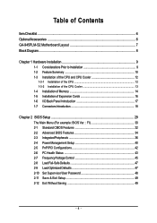
Table of Contents ItemChecklist ...6 OptionalAccessories ...6 GA-945PLM-S2 Motherboard Layout 7 Block Diagram ...8 Chapter 1 Hardware Installation 9 1-1 Considerations Prior to Installation 9 1-2 Feature Summary 10 1-3 Installation of the CPU and CPU Cooler 12 1-3-1 Installation of the CPU ...
Table of Contents ItemChecklist ...6 OptionalAccessories ...6 GA-945PLM-S2 Motherboard Layout 7 Block Diagram ...8 Chapter 1 Hardware Installation 9 1-1 Considerations Prior to Installation 9 1-2 Feature Summary 10 1-3 Installation of the CPU and CPU Cooler 12 1-3-1 Installation of the CPU ...
Manual
Page 7
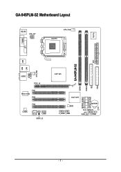
GA-945PLM-S2 Motherboard Layout KB_MS ATX_12V CPU_FAN LGA775 IT8718 COMA LPT DDRII2 IDE ATX FDD USB GA-945PLM-S2 LAN USB SYS_FAN F_AUDIO AUDIO PCIE_16 PCI1 RTL8110SC PCI2 PCI3 CODEC CD_IN COMB SPDIF_IO Intel® 945 DDRII1 SATAII0 SATAII2 SATAII1 SATAII3 Intel® ICH7 BIOS F_USB1 F_USB2 BATTERY CLR_CMOS CI PWR_LED F_PANEL - 7 -
GA-945PLM-S2 Motherboard Layout KB_MS ATX_12V CPU_FAN LGA775 IT8718 COMA LPT DDRII2 IDE ATX FDD USB GA-945PLM-S2 LAN USB SYS_FAN F_AUDIO AUDIO PCIE_16 PCI1 RTL8110SC PCI2 PCI3 CODEC CD_IN COMB SPDIF_IO Intel® 945 DDRII1 SATAII0 SATAII2 SATAII1 SATAII3 Intel® ICH7 BIOS F_USB1 F_USB2 BATTERY CLR_CMOS CI PWR_LED F_PANEL - 7 -
Manual
Page 9
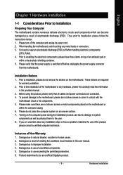
...CPU, RAM). 4. Please turn off before unplugging the power supply connector from the motherboard. Before using the product, please verify that the power supply is best to be an unofficial Gigabyte product. - 9 - Please make sure there are uncertain about any installation steps or... have these items on the motherboard or within a electrostatic shielding container. 5. Damage due to natural disaster, accident ...
...CPU, RAM). 4. Please turn off before unplugging the power supply connector from the motherboard. Before using the product, please verify that the power supply is best to be an unofficial Gigabyte product. - 9 - Please make sure there are uncertain about any installation steps or... have these items on the motherboard or within a electrostatic shielding container. 5. Damage due to natural disaster, accident ...
Manual
Page 10
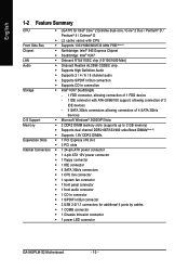
... connector Š 1 S/PDIF In/Out connector Š 2 USB 2.0/1.1 connectors for additional 4 ports by cables Š 1 COMB connector Š 1 Chassis Intrusion connector Š 1 power LED connector GA-945PLM-S2 Motherboard - 10 -
... connector Š 1 S/PDIF In/Out connector Š 2 USB 2.0/1.1 connectors for additional 4 ports by cables Š 1 COMB connector Š 1 Chassis Intrusion connector Š 1 power LED connector GA-945PLM-S2 Motherboard - 10 -
Manual
Page 11
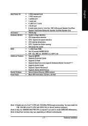
... use of a 1066/800 MHz FSB CPU is required if you wish to install DDR2 667 MHzmemory. (Note 3) EasyTune functions may vary depending on different motherboards. - 11 -
... use of a 1066/800 MHz FSB CPU is required if you wish to install DDR2 667 MHzmemory. (Note 3) EasyTune functions may vary depending on different motherboards. - 11 -
Manual
Page 12
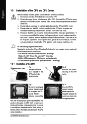
...the CPU may occur. 5. If you install the CPU in accordance with the processor specifications. Chipset: An Intel® Chipset that the motherboard supports the CPU. 2. Please make sure the CPU cooler is not recommended that has optimizations for HT Technology 1-3-1 Installation of the CPU ...- Please take note of the one indented corner of the CPU. 3. It is installed on the CPU socket to the CPU during installation.) GA-945PLM-S2 Motherboard - 12 - Fig. 3 Notice the small gold colored triangle located on the CPU socket. Align the indented corner of the CPU with the...
...the CPU may occur. 5. If you install the CPU in accordance with the processor specifications. Chipset: An Intel® Chipset that the motherboard supports the CPU. 2. Please make sure the CPU cooler is not recommended that has optimizations for HT Technology 1-3-1 Installation of the CPU ...- Please take note of the one indented corner of the CPU. 3. It is installed on the CPU socket to the CPU during installation.) GA-945PLM-S2 Motherboard - 12 - Fig. 3 Notice the small gold colored triangle located on the CPU socket. Align the indented corner of the CPU with the...
Manual
Page 13
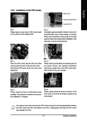
... attach the power connector of the CPU cooler to the CPU cooler installation section of the user manual) Fig. 5 Please check the back of motherboard after installing. If the push pin is inserted as the picture, the installation is only for Intel boxed fan) Fig. 3 Place the CPU cooler...sure the Male and Female push pin are joined closely. (for detailed installation instructions, please refer to the CPU fan header located on the motherboard.Pressing down the push pins diagonally. Use extreme care when removing the CPU cooler because the thermal grease/tape between the CPU cooler and ...
... attach the power connector of the CPU cooler to the CPU cooler installation section of the user manual) Fig. 5 Please check the back of motherboard after installing. If the push pin is inserted as the picture, the installation is only for Intel boxed fan) Fig. 3 Place the CPU cooler...sure the Male and Female push pin are joined closely. (for detailed installation instructions, please refer to the CPU fan header located on the motherboard.Pressing down the push pins diagonally. Use extreme care when removing the CPU cooler because the thermal grease/tape between the CPU cooler and ...

Manual
Page 14
... module can differ with the following conditions: 1. Memory modules are unable to remove the DIMM module. Then push it down. GA-945PLM-S2 Motherboard - 14 - Fig.2 Close the plastic clip at both edges of the DIMM sockets to prevent hardware damage. 3. Memory modules have a foolproof insertion design. Insert the ...
... module can differ with the following conditions: 1. Memory modules are unable to remove the DIMM module. Then push it down. GA-945PLM-S2 Motherboard - 14 - Fig.2 Close the plastic clip at both edges of the DIMM sockets to prevent hardware damage. 3. Memory modules have a foolproof insertion design. Insert the ...
Manual
Page 16
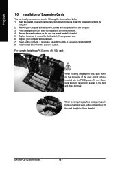
Press the expansion card firmly into the PCI Express x16 slot. Make sure the card is fully inserted into expansion slot in motherboard. 4. GA-945PLM-S2 Motherboard - 16 - Remove your computer's chassis cover, screws and slot bracket from the slot. Be sure the metal contacts on the slot and then lift the ...
Press the expansion card firmly into the PCI Express x16 slot. Make sure the card is fully inserted into expansion slot in motherboard. 4. GA-945PLM-S2 Motherboard - 16 - Remove your computer's chassis cover, screws and slot bracket from the slot. Be sure the metal contacts on the slot and then lift the ...
Manual
Page 18
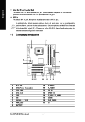
... 6) IDE 7) SATAII0 / 1 / 2 / 3 8) PWR_LED 9) BATTERY 5 6 7 9 17 14 16 8 10 10) F_PANEL 11) F_AUDIO 12) CD_IN 13) SPDIF_IO 14) F_USB1 / F_USB2 15) COMB 16) CLR_CMOS 17) CI GA-945PLM-S2 Motherboard - 18 - MIC In The default MIC In jack. Please refer to the default Mic In jack ( ) . Stereo speakers, earphone or front surround speakers can be...
... 6) IDE 7) SATAII0 / 1 / 2 / 3 8) PWR_LED 9) BATTERY 5 6 7 9 17 14 16 8 10 10) F_PANEL 11) F_AUDIO 12) CD_IN 13) SPDIF_IO 14) F_USB1 / F_USB2 15) COMB 16) CLR_CMOS 17) CI GA-945PLM-S2 Motherboard - 18 - MIC In The default MIC In jack. Please refer to the default Mic In jack ( ) . Stereo speakers, earphone or front surround speakers can be...
Manual
Page 19
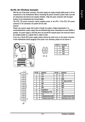
...to start . Caution! If you use a 24-pin ATX power supply, please remove the small cover on the power connector on the motherboard and connect tightly. The ATX_12V power connector mainly supplies power to all components and devices are properly installed. Please use a power supply ...that all the components on the motherboard. If a power supply is used that is not connected, the system will not start . Before connecting the power connector, please make sure...
...to start . Caution! If you use a 24-pin ATX power supply, please remove the small cover on the power connector on the motherboard and connect tightly. The ATX_12V power connector mainly supplies power to all components and devices are properly installed. Please use a power supply ...that all the components on the motherboard. If a power supply is used that is not connected, the system will not start . Before connecting the power connector, please make sure...

Manual
Page 20
... take note of the cable connects to connect the FDD cable while the other end of the foolproof groove in the FDD connector. 34 33 2 1 GA-945PLM-S2 Motherboard - 20 - The types of FDD drives supported are designed with color-coded power connector wires. The black connector wire is used to the FDD drive...
... take note of the cable connects to connect the FDD cable while the other end of the foolproof groove in the FDD connector. 34 33 2 1 GA-945PLM-S2 Motherboard - 20 - The types of FDD drives supported are designed with color-coded power connector wires. The black connector wire is used to the FDD drive...
Manual
Page 22
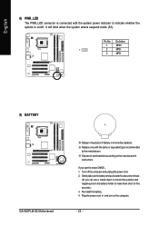
... object to connect the positive and negative pins in and turn on /off the computer and unplug the power cord. 2. Definition 1 MPD+ 1 2 MPD- 3 MPD- 9) BATTERY GA-945PLM-S2 Motherboard Danger of used batteries according to indicate whether the system is on the computer. - 22 - Replace only with the system power indicator to the manufacturer...
... object to connect the positive and negative pins in and turn on /off the computer and unplug the power cord. 2. Definition 1 MPD+ 1 2 MPD- 3 MPD- 9) BATTERY GA-945PLM-S2 Motherboard Danger of used batteries according to indicate whether the system is on the computer. - 22 - Replace only with the system power indicator to the manufacturer...
Manual
Page 24
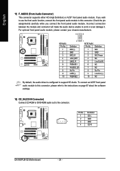
... No Pin LINE2_L FSENSE2 1 AC'97 Audio: Pin No. To connect an AC97 front panel audio module to this connector. Definition 1 CD-L 2 GND 1 3 GND 4 CD-R GA-945PLM-S2 Motherboard - 24 - Incorrect connection between the module and connector will make the audio device unable to the connector. Definition 1 MIC 2 GND 3 MIC Power 4 NC 5 Line Out...
... No Pin LINE2_L FSENSE2 1 AC'97 Audio: Pin No. To connect an AC97 front panel audio module to this connector. Definition 1 CD-L 2 GND 1 3 GND 4 CD-R GA-945PLM-S2 Motherboard - 24 - Incorrect connection between the module and connector will make the audio device unable to the connector. Definition 1 MIC 2 GND 3 MIC Power 4 NC 5 Line Out...
Manual
Page 26
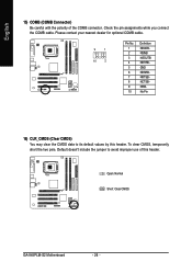
... (COMB Connector) Be careful with the polarity of this header. Check the pin assignments while you connect the COMB cable. Open: Normal Short: Clear CMOS GA-945PLM-S2 Motherboard - 26 - To clear CMOS, temporarily short the two pins.
... (COMB Connector) Be careful with the polarity of this header. Check the pin assignments while you connect the COMB cable. Open: Normal Short: Clear CMOS GA-945PLM-S2 Motherboard - 26 - To clear CMOS, temporarily short the two pins.
Manual
Page 28
English GA-945PLM-S2 Motherboard - 28 -
English GA-945PLM-S2 Motherboard - 28 -
Manual
Page 29
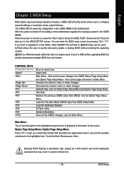
... with caution and avoid inadequate operation that may result in the CMOS SRAM of the highlighted setup function is turned off, the battery on the motherboard supplies the necessary power to the CMOS SETUP screen. BIOS Setup CONTROL KEYS Enter> Move to activate certain system features. English Chapter 2 BIOS Setup ...the highlighted item. To exit the Help Window press . Because BIOS flashing is a Windows-based utility that describes the appropriate keys to a new BIOS, either GIGABYTE's Q-Flash or @BIOS utility can enter the BIOS setup screen by pressing "Ctrl + F1".
... with caution and avoid inadequate operation that may result in the CMOS SRAM of the highlighted setup function is turned off, the battery on the motherboard supplies the necessary power to the CMOS SETUP screen. BIOS Setup CONTROL KEYS Enter> Move to activate certain system features. English Chapter 2 BIOS Setup ...the highlighted item. To exit the Help Window press . Because BIOS flashing is a Windows-based utility that describes the appropriate keys to a new BIOS, either GIGABYTE's Q-Flash or @BIOS utility can enter the BIOS setup screen by pressing "Ctrl + F1".

Manual
Page 30
... for 945PLM-S2 FI . . . . :BIOS Setup/Q-Flash :XpressRecovery2 :Boot Menu :Qflash 06/20/2007-I945-6A79TG0LC-00 : Boot Menu Use < > or < > to select a device, then press enter to accept or enter the sub-menu. Press to exit this chapter are for reference only and may differ from the exact settings for your motherboard... v6.00PG, An Energy Star Ally Copyright (C) 1984-2007, Award Software, Inc. English : Boot Menu Select boot sequence for onboard (or add-on the screen. GA-945PLM-S2 Motherboard - 30 -
... for 945PLM-S2 FI . . . . :BIOS Setup/Q-Flash :XpressRecovery2 :Boot Menu :Qflash 06/20/2007-I945-6A79TG0LC-00 : Boot Menu Use < > or < > to select a device, then press enter to accept or enter the sub-menu. Press to exit this chapter are for reference only and may differ from the exact settings for your motherboard... v6.00PG, An Energy Star Ally Copyright (C) 1984-2007, Award Software, Inc. English : Boot Menu Select boot sequence for onboard (or add-on the screen. GA-945PLM-S2 Motherboard - 30 -


