User Manual
Page 6
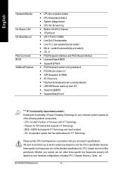
English Table of Content Item Checklist 4 WARNING 4 Chapter 1 Introduction 5 Features Summary 5 GA-8VM533 Motherboard Layout 7 Block Diagram 8 Chapter 2 Hardware Installation Process 11 Step 1: Install the Central Processing Unit (CPU 12 Step 1-1: CPU ...16 Step 4: Connect ribbon cables, cabinet wires and power supply 17 Step 4-1: I/O Back Panel Introduction 17 Step 4-2: Connectors Introduction 19 Chapter 3 BIOS Setup 27 The Main Menu (For example: BIOS Ver. : F1 28 Standard CMOS Features 30 Advanced BIOS Features 33 Integrated Peripherals 35 Power Management Setup 38...
English Table of Content Item Checklist 4 WARNING 4 Chapter 1 Introduction 5 Features Summary 5 GA-8VM533 Motherboard Layout 7 Block Diagram 8 Chapter 2 Hardware Installation Process 11 Step 1: Install the Central Processing Unit (CPU 12 Step 1-1: CPU ...16 Step 4: Connect ribbon cables, cabinet wires and power supply 17 Step 4-1: I/O Back Panel Introduction 17 Step 4-2: Connectors Introduction 19 Chapter 3 BIOS Setup 27 The Main Menu (For example: BIOS Ver. : F1 28 Standard CMOS Features 30 Advanced BIOS Features 33 Integrated Peripherals 35 Power Management Setup 38...

User Manual
Page 7
Table of Content English PnP/PCI Configurations 41 PC Health Status 42 Frequency/Voltage Control 43 Load Fail-Safe Defaults 45 Load Optimized Defaults 46 Set Supervisor/User Password 47 Save & Exit Setup 48 Exit Without Saving 49 Chapter 4 Technical Reference 51 @BIOS™ Introduction 51 EasyTune™ 4 Introduction 52 Flash BIOS Method Introduction 53 Method 1 : Q-Flash 53 Method 2 : @BIOS Utility 66 6-Channel Audio Function Introduction 68 Xpress Recovery Introduction 71 Chapter 5 Appendix 75 - 3 -
Table of Content English PnP/PCI Configurations 41 PC Health Status 42 Frequency/Voltage Control 43 Load Fail-Safe Defaults 45 Load Optimized Defaults 46 Set Supervisor/User Password 47 Save & Exit Setup 48 Exit Without Saving 49 Chapter 4 Technical Reference 51 @BIOS™ Introduction 51 EasyTune™ 4 Introduction 52 Flash BIOS Method Introduction 53 Method 1 : Q-Flash 53 Method 2 : @BIOS Utility 66 6-Channel Audio Function Introduction 68 Xpress Recovery Introduction 71 Chapter 5 Appendix 75 - 3 -
User Manual
Page 10
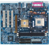
...requirement content : Enabling the functionality of Hyper-Threading Technology for HT Technology Please set the system bus frequency over -currentprotection - BIOS: A BIOS that supports HT Technology - etc. AC Recovery - USB KB/Mouse wake up from S3 - PS/2 Mouse power on your... to set the CPU host frequency in VIA 6103 Chipset - 1 RJ45 port - Supports Q-Flash - System voltage detect - Line Out/ 2 frontspeaker - GA-8VM533 Motherboard - 6 - Builit in accordance with HT Technology - CD_In - CPU: An Intel® Pentium 4 Processor with your system can run under ...
...requirement content : Enabling the functionality of Hyper-Threading Technology for HT Technology Please set the system bus frequency over -currentprotection - BIOS: A BIOS that supports HT Technology - etc. AC Recovery - USB KB/Mouse wake up from S3 - PS/2 Mouse power on your... to set the CPU host frequency in VIA 6103 Chipset - 1 RJ45 port - Supports Q-Flash - System voltage detect - Line Out/ 2 frontspeaker - GA-8VM533 Motherboard - 6 - Builit in accordance with HT Technology - CD_In - CPU: An Intel® Pentium 4 Processor with your system can run under ...
User Manual
Page 15
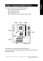
You haveaccomplished the hardware installation! Continue with the BIOS/software installation. - 11 - Install the Central Processing Unit (CPU) Step 2- Install memory modules Step 3- Turn on the power supply or connect the power cable to the power outlet. Install expansion cards Step 4- Hardware Installation Process English Chapter 2 Hardware Installation Process To set up your computer, you must complete the following steps: Step 1- Connect ribbon cables, cabinet wires, and power supply Step 4 Step 1 Step 2 Step 4 Step 3 Step 4 Congratulations!
You haveaccomplished the hardware installation! Continue with the BIOS/software installation. - 11 - Install the Central Processing Unit (CPU) Step 2- Install memory modules Step 3- Turn on the power supply or connect the power cable to the power outlet. Install expansion cards Step 4- Hardware Installation Process English Chapter 2 Hardware Installation Process To set up your computer, you must complete the following steps: Step 1- Connect ribbon cables, cabinet wires, and power supply Step 4 Step 1 Step 2 Step 4 Step 3 Step 4 Congratulations!
User Manual
Page 18
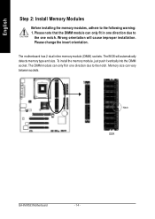
..., just push it vertically into the DIMM so cket. The motherboard has 2 dual inline memory module (DIMM) sockets. Notch DDR GA-8VM533 Motherboard - 14 - Please change the insert orientation. The BIOS will cause improper installation. Th e DIMM module ca n on ly fit in one notch. Please note that the DIMM module can...
..., just push it vertically into the DIMM so cket. The motherboard has 2 dual inline memory module (DIMM) sockets. Notch DDR GA-8VM533 Motherboard - 14 - Please change the insert orientation. The BIOS will cause improper installation. Th e DIMM module ca n on ly fit in one notch. Please note that the DIMM module can...

User Manual
Page 20
...Make sure your computer's chassis cover. 7. Press the expansion card firmly into the computer. 2. Replace your AGP card is locked by the small white- GA-8VM533 Motherboard - 16 - Power on the card are indeed seated in the slot. 5. Be sure the metalcontacts on the computer, ifnecessary, setup... BIOS utility of the AGP slot when you try to install/ Uninstall the AGP card. Please align the AGPcard to secure the slotbracketofthe expansion card. 6....
...Make sure your computer's chassis cover. 7. Press the expansion card firmly into the computer. 2. Replace your AGP card is locked by the small white- GA-8VM533 Motherboard - 16 - Power on the card are indeed seated in the slot. 5. Be sure the metalcontacts on the computer, ifnecessary, setup... BIOS utility of the AGP slot when you try to install/ Uninstall the AGP card. Please align the AGPcard to secure the slotbracketofthe expansion card. 6....

User Manual
Page 31
..., pressing immediately during POST (Power On Self Test) itw ill allow y ou to modify the basic system configuration. BIOS Setup ENTERING S ETUP After pow er on the BIOS screen. Exit current page and return to the item in the left hand Move to Main Menu Increase the numeric value...ed Reserv ed Restore the previous CMOS value from CMOS, only for Option Page Setup Menu Load the file-safe default CMOS value from BIOS default table Load the Optimized Defaults Q-Flash function System Information Save all the CMOS changes, only for Main Menu - 27 - This type of...
..., pressing immediately during POST (Power On Self Test) itw ill allow y ou to modify the basic system configuration. BIOS Setup ENTERING S ETUP After pow er on the BIOS screen. Exit current page and return to the item in the left hand Move to Main Menu Increase the numeric value...ed Reserv ed Restore the previous CMOS value from CMOS, only for Option Page Setup Menu Load the file-safe default CMOS value from BIOS default table Load the Optimized Defaults Q-Flash function System Information Save all the CMOS changes, only for Main Menu - 27 - This type of...
User Manual
Page 32
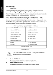
l Standard CMOS Features This setup page includes all the items of the screen. GA-8VM533 Motherboard - 28 - The Main Menu (For example: BIOS Ver. : F1) Once you enterAward BIOS CMOS Setup Utility, the Main Menu (Figure 1) will appear on -line description of the highlighted setup function ... features. CMOS Setup Utility -Copy right (C) 1984-2003 Aw ard Softw are }Standard CMOS Features Load Fail-Safe Defaults }Adv anced BIOS Features Load Optimized Defaults }Integrated Peripherals Set Superv isor Passw ord }Pow er Management Setup Set User Passw ord }PnP/PCI Configurations Sav...
l Standard CMOS Features This setup page includes all the items of the screen. GA-8VM533 Motherboard - 28 - The Main Menu (For example: BIOS Ver. : F1) Once you enterAward BIOS CMOS Setup Utility, the Main Menu (Figure 1) will appear on -line description of the highlighted setup function ... features. CMOS Setup Utility -Copy right (C) 1984-2003 Aw ard Softw are }Standard CMOS Features Load Fail-Safe Defaults }Adv anced BIOS Features Load Optimized Defaults }Integrated Peripherals Set Superv isor Passw ord }Pow er Management Setup Set User Passw ord }PnP/PCI Configurations Sav...

User Manual
Page 33
.... It allows you to limit access to the system and Setup, or just to Setup. l Save & Exit Setup Save CMOS value settings to the system. BIOS Setup It allows you to limit access to CMOS and exit setup. l Power Manag ement Setup This setup page includes all the configurations of the...
.... It allows you to limit access to the system and Setup, or just to Setup. l Save & Exit Setup Save CMOS value settings to the system. BIOS Setup It allows you to limit access to CMOS and exit setup. l Power Manag ement Setup This setup page includes all the configurations of the...
User Manual
Page 34
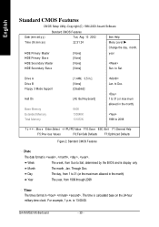
... The year, from Sun to 31 (or max imum allow ed in . to Dec. 1 to Sat, determined by the BIOS and is calculated base on the 24-hour military-time clock. is , , , . GA-8VM533 Motherboard - 30 - The time is display only Month The month, Jan. to 31 (or the maximum allowed in...
... The year, from Sun to 31 (or max imum allow ed in . to Dec. 1 to Sat, determined by the BIOS and is calculated base on the 24-hour military-time clock. is , , , . GA-8VM533 Motherboard - 30 - The time is display only Month The month, Jan. to 31 (or the maximum allowed in...

User Manual
Page 35
... PC-type standard drive; 360K byte capacity. 1.2M, 5.25". 5.25 inch AT-type high-density drive; 1.2M byte capacity (3.5 inch when 3 Mode is user-definable; BIOS Setup Note thatthe specifications of your hard disk vendor or the system manufacturer. The hard disk willnot work properly if you select User Type, related...
... PC-type standard drive; 360K byte capacity. 1.2M, 5.25". 5.25 inch AT-type high-density drive; 1.2M byte capacity (3.5 inch when 3 Mode is user-definable; BIOS Setup Note thatthe specifications of your hard disk vendor or the system manufacturer. The hard disk willnot work properly if you select User Type, related...
User Manual
Page 36
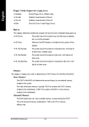
... for all other errors. (Default value) All, But Diskette The system boot will not stop for a disk error; GA-8VM533 Motherboard - 32 - Base Memory The POST of the BIOS will not stop for a keyboard or disk error; This is the amount of base (or conv entional) memory installed ... address map. English Floppy 3 Mode Support (for J apan Area) Disabled Normal Floppy Drive. (Default value) Drive A Enabled 3 mode function of the BIOS. All, But Keyboar The system boot will determine the amount of memory located above 1 MB in the system. The value of Drive B. NO Errors The...
... for all other errors. (Default value) All, But Diskette The system boot will not stop for a disk error; GA-8VM533 Motherboard - 32 - Base Memory The POST of the BIOS will not stop for a keyboard or disk error; This is the amount of base (or conv entional) memory installed ... address map. English Floppy 3 Mode Support (for J apan Area) Disabled Normal Floppy Drive. (Default value) Drive A Enabled 3 mode function of the BIOS. All, But Keyboar The system boot will determine the amount of memory located above 1 MB in the system. The value of Drive B. NO Errors The...

User Manual
Page 37
...Select your boot device priority by SCSI. U SB-FDD Select your boot device priority by LS120. English Advanced BIOS Features CMOS Setup Utility -Copy right (C) 1984-2003 Aw ard Softw are Adv anced BIOS Features First Boot Dev ice [Floppy ] Item Help Second Boot Dev ice [HDD-0] Menu Lev el u... +/-/PU/PD:Value F10:Sav e ESC:Ex it F1:General Help F5:Prev ious Values F6:Fail-Safe Defaults F7:Optimized Defaults Figure 3: Adv anced BIOS Features " # " System will detect automatically and show up when you to select the boot device priority. First / Second / Third Boot device M This ...
...Select your boot device priority by SCSI. U SB-FDD Select your boot device priority by LS120. English Advanced BIOS Features CMOS Setup Utility -Copy right (C) 1984-2003 Aw ard Softw are Adv anced BIOS Features First Boot Dev ice [Floppy ] Item Help Second Boot Dev ice [HDD-0] Menu Lev el u... +/-/PU/PD:Value F10:Sav e ESC:Ex it F1:General Help F5:Prev ious Values F6:Fail-Safe Defaults F7:Optimized Defaults Figure 3: Adv anced BIOS Features " # " System will detect automatically and show up when you to select the boot device priority. First / Second / Third Boot device M This ...

User Manual
Page 39
.../PD:Value F10:Sav e ESC:Ex it F1:General Help F5:Prev ious Values F6:Fail-Safe Defaults F7:Optimized Defaults Figure 4: Integrated Peripherals - 35 - BIOS Setup
.../PD:Value F10:Sav e ESC:Ex it F1:General Help F5:Prev ious Values F6:Fail-Safe Defaults F7:Optimized Defaults Figure 4: Integrated Peripherals - 35 - BIOS Setup

User Manual
Page 41
Disabled Disable onboard parallel port. BIOS Setup Disabled Disable onboard Serial port 1. OnBoard Parallel port M This feature allows you to select from a given set of parameters if the parallel port uses ... mode it supports. ECP+EPP Using Parallel port as Standard Parallel Port using IRQ7. Disabled Disable USB Mouse Support. (Default value) Onboard Serial Port 1 Auto BIOS will automatically setup the port 1 address. 3F8/IRQ4 Enable onboard Serial port 1 and address is 3F8,Using IRQ4. (Default value) 2F8/IRQ3 Enable onboard Serial...
Disabled Disable onboard parallel port. BIOS Setup Disabled Disable onboard Serial port 1. OnBoard Parallel port M This feature allows you to select from a given set of parameters if the parallel port uses ... mode it supports. ECP+EPP Using Parallel port as Standard Parallel Port using IRQ7. Disabled Disable USB Mouse Support. (Default value) Onboard Serial Port 1 Auto BIOS will automatically setup the port 1 address. 3F8/IRQ4 Enable onboard Serial port 1 and address is 3F8,Using IRQ4. (Default value) 2F8/IRQ3 Enable onboard Serial...
User Manual
Page 43
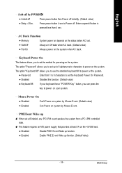
... powering-on system by PWRBTN Instant-off Press power button then Power off instantly. (Default value) Delay 4 Sec. Enabled Enable PME Event Wake up function. BIOS Setup English Soft-off by Mouse Event. AC Back Function Memory System power on depends on the system when AC back. Enter suspend if button...
... powering-on system by PWRBTN Instant-off Press power button then Power off instantly. (Default value) Delay 4 Sec. Enabled Enable PME Event Wake up function. BIOS Setup English Soft-off by Mouse Event. AC Back Function Memory System power on depends on the system when AC back. Enter suspend if button...
User Manual
Page 45
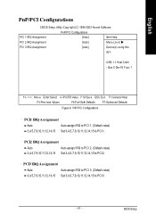
... Cntrlr - PCI3 IRQ Assignment Auto Auto assign IRQ to PCI 3. (Default value) 3,4,5,7,9,10,11,12,14,15 Set 3,4,5,7,9,10,11,12,14,15 to PCI2. BIOS Setup Bus 0 Dev 16 Func 1 higf: Mov e Enter:Select +/-/PU/PD:Value F10:Sav e ESC:Ex it F1:General Help F5:Prev ious Values F6...
... Cntrlr - PCI3 IRQ Assignment Auto Auto assign IRQ to PCI 3. (Default value) 3,4,5,7,9,10,11,12,14,15 Set 3,4,5,7,9,10,11,12,14,15 to PCI2. BIOS Setup Bus 0 Dev 16 Func 1 higf: Mov e Enter:Select +/-/PU/PD:Value F10:Sav e ESC:Ex it F1:General Help F5:Prev ious Values F6...

User Manual
Page 47
...~24X default: 15X For N orthwood CPU: 12X~24X default: 16X The option w ill display "Locked" and read only if the CPU ratio is not changeable. BIOS Setup This setup option will automatically assign by CPU detection. Auto Detect PCI/DIMM Clk Disabled Disable auto detect PCI/DIMM Clk. English Frequency/Voltage...
...~24X default: 15X For N orthwood CPU: 12X~24X default: 16X The option w ill display "Locked" and read only if the CPU ratio is not changeable. BIOS Setup This setup option will automatically assign by CPU detection. Auto Detect PCI/DIMM Clk Disabled Disable auto detect PCI/DIMM Clk. English Frequency/Voltage...

User Manual
Page 49
English Load Fail-Safe Defaults CMOS Setup Utility -Copy right (C) 1984-2003 Aw ard Softw are }Standard CMOS Features Load Fail-Safe Defaults }Adv anced BIOS Features Load Optimized Defaults }Integrated Peripherals Set Superv isor Passw ord }Pow er Management Setup Set User Passw ord }PnP/PCI Configurations Sav e & Ex it ... Fail-Safe Defaults Load Fail-Safe Defaults Fail-Safe defaults contain the most appropriate values of the system parameters that allow minimum system performance. - 45 - BIOS Setup
English Load Fail-Safe Defaults CMOS Setup Utility -Copy right (C) 1984-2003 Aw ard Softw are }Standard CMOS Features Load Fail-Safe Defaults }Adv anced BIOS Features Load Optimized Defaults }Integrated Peripherals Set Superv isor Passw ord }Pow er Management Setup Set User Passw ord }PnP/PCI Configurations Sav e & Ex it ... Fail-Safe Defaults Load Fail-Safe Defaults Fail-Safe defaults contain the most appropriate values of the system parameters that allow minimum system performance. - 45 - BIOS Setup

User Manual
Page 50
GA-8VM533 Motherboard - 46 - English Load Optimized Defaults CMOS Setup Utility -Copy right (C) 1984-2003 Aw ard Softw are }Standard CMOS Features Load Fail-Safe Defaults }Adv anced BIOS Features Load Optimized Defaults }Integrated Peripherals Set Superv isor Passw ord }Pow er Management Setup Set User Passw ord }PnP/PCFIigCuornefi1g1u: rLaLotiooandasFdaOil...F10:Sav e & Ex it Setup Load Optimized Defaults Figure 10: Load Optimized Defaults Load OptimizedDefaults Selecting this field loads the factory defaults for BIOS and Chipset Features which the system automatically detects.
GA-8VM533 Motherboard - 46 - English Load Optimized Defaults CMOS Setup Utility -Copy right (C) 1984-2003 Aw ard Softw are }Standard CMOS Features Load Fail-Safe Defaults }Adv anced BIOS Features Load Optimized Defaults }Integrated Peripherals Set Superv isor Passw ord }Pow er Management Setup Set User Passw ord }PnP/PCFIigCuornefi1g1u: rLaLotiooandasFdaOil...F10:Sav e & Ex it Setup Load Optimized Defaults Figure 10: Load Optimized Defaults Load OptimizedDefaults Selecting this field loads the factory defaults for BIOS and Chipset Features which the system automatically detects.


