User Manual
Page 6
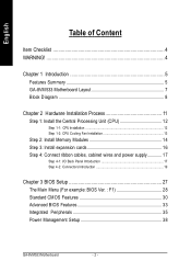
... Summary 5 GA-8VM533 Motherboard Layout 7 Block Diagram 8 Chapter 2 Hardware Installation Process 11 Step 1: Install the Central Processing Unit (CPU 12 Step 1-1: CPU Installation 12 Step 1-2: CPU Cooling Fan Installation 13 Step 2: Install Memory Modules 14 Step 3: Install expansion cards 16 Step 4: Connect ribbon cables, cabinet wires and power supply 17 Step 4-1: I/O Back Panel Introduction 17 Step 4-2: Connectors Introduction 19 Chapter 3 BIOS Setup 27 The Main Menu (For example: BIOS Ver. : F1 28 Standard CMOS Features 30 Advanced BIOS Features 33...
... Summary 5 GA-8VM533 Motherboard Layout 7 Block Diagram 8 Chapter 2 Hardware Installation Process 11 Step 1: Install the Central Processing Unit (CPU 12 Step 1-1: CPU Installation 12 Step 1-2: CPU Cooling Fan Installation 13 Step 2: Install Memory Modules 14 Step 3: Install expansion cards 16 Step 4: Connect ribbon cables, cabinet wires and power supply 17 Step 4-1: I/O Back Panel Introduction 17 Step 4-2: Connectors Introduction 19 Chapter 3 BIOS Setup 27 The Main Menu (For example: BIOS Ver. : F1 28 Standard CMOS Features 30 Advanced BIOS Features 33...
User Manual
Page 8
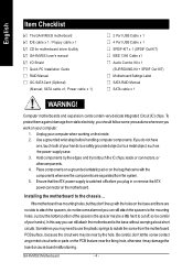
... by the hole. Power cable x 1) 2 Port USB Cable x 1 4 Port USB Cable x 1 SPDIF-KIT x 1 (SPDIF Out KIT) IEEE 1394 Cable x1 Audio Combo Kit x 1 (SURROUND-Kit + SPDIF Out KIT) Motherboard Settings Label SATA RAID Manual SATA cable x 1 WARNING! Unplug yourcomputer when working on the motherboard. English Item Checklist The GA-8VM533 motherboard IDE cable x 1 / Floppy cable x 1 CD for motherboard driver & utility GA-8VM533 user's manual I/O Shield Quick PC Installation Guide RAID Manual GC-SATA Card (Optional) (M anual; Ensure that the ATX power supply is switched offbefore you should...
... by the hole. Power cable x 1) 2 Port USB Cable x 1 4 Port USB Cable x 1 SPDIF-KIT x 1 (SPDIF Out KIT) IEEE 1394 Cable x1 Audio Combo Kit x 1 (SURROUND-Kit + SPDIF Out KIT) Motherboard Settings Label SATA RAID Manual SATA cable x 1 WARNING! Unplug yourcomputer when working on the motherboard. English Item Checklist The GA-8VM533 motherboard IDE cable x 1 / Floppy cable x 1 CD for motherboard driver & utility GA-8VM533 user's manual I/O Shield Quick PC Installation Guide RAID Manual GC-SATA Card (Optional) (M anual; Ensure that the ATX power supply is switched offbefore you should...
User Manual
Page 10
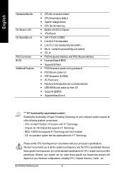
... content : Enabling the functionality of the following platform components: - BIOS: A BIOS that supports HT Technology - Builit in accordance with HT Technology - VIA VT1616 CODEC - CD_In - Supports Q-Flash - AC Recovery - OS: An operation system that has optimizations for HT Technology Please set the system bus frequency over -currentprotection - PS/2 Keyboard power on by s/w switch) - Whether your hardware configurations, including CPU, Chipsets, Memory, Cards... English Hardware Monitor On-Board LAN On-Board Sound PS/2 Connector BIOS Additional Features...
... content : Enabling the functionality of the following platform components: - BIOS: A BIOS that supports HT Technology - Builit in accordance with HT Technology - VIA VT1616 CODEC - CD_In - Supports Q-Flash - AC Recovery - OS: An operation system that has optimizations for HT Technology Please set the system bus frequency over -currentprotection - PS/2 Keyboard power on by s/w switch) - Whether your hardware configurations, including CPU, Chipsets, Memory, Cards... English Hardware Monitor On-Board LAN On-Board Sound PS/2 Connector BIOS Additional Features...
User Manual
Page 15
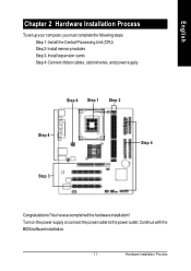
Install memory modules Step 3- You haveaccomplished the hardware installation! Connect ribbon cables, cabinet wires, and power supply Step 4 Step 1 Step 2 Step 4 Step 3 Step 4 Congratulations! Install expansion cards Step 4- Continue with the BIOS/software installation. - 11 - Turn on the power supply or connect the power cable to the power outlet. Install the Central Processing Unit (CPU) Step 2- English Chapter 2 Hardware Installation Process To set up your computer, you must complete the following steps: Step 1- Hardware Installation Process
Install memory modules Step 3- You haveaccomplished the hardware installation! Connect ribbon cables, cabinet wires, and power supply Step 4 Step 1 Step 2 Step 4 Step 3 Step 4 Congratulations! Install expansion cards Step 4- Continue with the BIOS/software installation. - 11 - Turn on the power supply or connect the power cable to the power outlet. Install the Central Processing Unit (CPU) Step 2- English Chapter 2 Hardware Installation Process To set up your computer, you must complete the following steps: Step 1- Hardware Installation Process
User Manual
Page 22
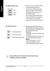
...) MIC In(Center and Subwoofer) After install onboard audio driver, you have 1 choose for hardware connection. If you want the detail information for possible patch ordriverupgrade.Formore information please contact your OS supports USBcontroller. If your OS does not support USB controller, please contactOSvendor for 6-channel audio setup installation, please refer to page 68. GA-8VM533 Motherboard - 18 - English w USB / LAN Connector LAN USB 0 USB 1 Before you want to ena ble...
...) MIC In(Center and Subwoofer) After install onboard audio driver, you have 1 choose for hardware connection. If you want the detail information for possible patch ordriverupgrade.Formore information please contact your OS supports USBcontroller. If your OS does not support USB controller, please contactOSvendor for 6-channel audio setup installation, please refer to page 68. GA-8VM533 Motherboard - 18 - English w USB / LAN Connector LAN USB 0 USB 1 Before you want to ena ble...

User Manual
Page 35
... of hard disk. BIOS Setup C apacity : The hard disk size. H ead The read /write) are seated when the disk drive is Enabled). 720K, 3.5". 3.5 inch double-sided drive; 720K byte capacity 1.44M, 3.5". 3.5 inch double-sided drive; 1.44M byte capacity. 2.88M, 3.5". 3.5 inch double-sided drive; 2.88M byte capacity. - 31 - If a hard disk has not been installed select NONE and press . If you enter improper information for this category. Access Mode: The options...
... of hard disk. BIOS Setup C apacity : The hard disk size. H ead The read /write) are seated when the disk drive is Enabled). 720K, 3.5". 3.5 inch double-sided drive; 720K byte capacity 1.44M, 3.5". 3.5 inch double-sided drive; 1.44M byte capacity. 2.88M, 3.5". 3.5 inch double-sided drive; 2.88M byte capacity. - 31 - If a hard disk has not been installed select NONE and press . If you enter improper information for this category. Access Mode: The options...

User Manual
Page 39
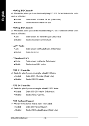
... CMOS Setup Utility -Copy right (C) 1984-2003 Aw ard Softw are Integrated Peripherals OnChip IDE Channel0 [Enabled] Item Help OnChip IDE Channel1 [Enabled] Menu Lev el u AC97 Audio [Auto] If a hard disk VIA onboard LAN [Enabled] controller card is USB 1.1 Controller USB 2.0 Controller USB Key board Support USB Mouse Support Onboard Serial Port 1 Onboard Parallel Port [Enabled] [Enabled] [Disabled] [Disabled] [3F8/IRQ4] [378/IRQ7] used, set at Disabled [Enabled] Enable onboard IDE Channel Parallel Port Mode [SPP] [Disabled] Disable onboard IDE Channel higf: Mov e Enter...
... CMOS Setup Utility -Copy right (C) 1984-2003 Aw ard Softw are Integrated Peripherals OnChip IDE Channel0 [Enabled] Item Help OnChip IDE Channel1 [Enabled] Menu Lev el u AC97 Audio [Auto] If a hard disk VIA onboard LAN [Enabled] controller card is USB 1.1 Controller USB 2.0 Controller USB Key board Support USB Mouse Support Onboard Serial Port 1 Onboard Parallel Port [Enabled] [Enabled] [Disabled] [Disabled] [3F8/IRQ4] [378/IRQ7] used, set at Disabled [Enabled] Enable onboard IDE Channel Parallel Port Mode [SPP] [Disabled] Disable onboard IDE Channel higf: Mov e Enter...
User Manual
Page 40
... (Default value) Disabled Disable onboard 1st channel IDE port. VIA onboard LAN Enable Enable onboard LAN function.(Default value) Disable Disable onboard LAN function. Disabled Disable USB Keyboard Support. (Default value) GA-8VM533 Motherboard - 36 - If a hard disk controller card is used , set at Disabled. Enabled Enable USB Keyboard Support. If a hard disk controller card is installed, please set at Disabled. USB 1.1 Controller M Disable this function. USB Keyboard Support M When a USB keyboard is used , set at Enabled. USB 2.0 Controller M Disable this option...
... (Default value) Disabled Disable onboard 1st channel IDE port. VIA onboard LAN Enable Enable onboard LAN function.(Default value) Disable Disable onboard LAN function. Disabled Disable USB Keyboard Support. (Default value) GA-8VM533 Motherboard - 36 - If a hard disk controller card is used , set at Disabled. Enabled Enable USB Keyboard Support. If a hard disk controller card is installed, please set at Disabled. USB 1.1 Controller M Disable this function. USB Keyboard Support M When a USB keyboard is used , set at Enabled. USB 2.0 Controller M Disable this option...

User Manual
Page 42
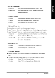
... e Enter:Select +/-/PU/PD:Value F10:Sav e ESC:Ex it F1:General Help F5:Prev ious Values F6:Fail-Safe Defaults F7:Optimized Defaults Figure 5: Pow er Management Setup ACPI Suspend Type S1/POS Set suspend type to Power On Suspend under ACPI OS (Power On Suspend). (Default value) S3/STR Set suspend type to S3/STR. Disabled USB Device can wakeup system from S3. (Default value) GA-8VM533 Motherboard - 38 - USB Device...
... e Enter:Select +/-/PU/PD:Value F10:Sav e ESC:Ex it F1:General Help F5:Prev ious Values F6:Fail-Safe Defaults F7:Optimized Defaults Figure 5: Pow er Management Setup ACPI Suspend Type S1/POS Set suspend type to Power On Suspend under ACPI OS (Power On Suspend). (Default value) S3/STR Set suspend type to S3/STR. Disabled USB Device can wakeup system from S3. (Default value) GA-8VM533 Motherboard - 38 - USB Device...
User Manual
Page 43
... set the Keyboard Power On Password. M This feature requires an ATX power supply that provides at Enabled, any PCI-PM event awakes the system from 1 to 8 characters to power on the system when AC back. Passw ord Enter from a PCI-PM controlled state. Mouse Power On Disabled Can't Power on system by PWRBTN Instant-off Press power button then Power off instantly. (Default value) Delay 4 Sec. Enabled Enable PME Event Wake up function. Disabled Disable...
... set the Keyboard Power On Password. M This feature requires an ATX power supply that provides at Enabled, any PCI-PM event awakes the system from 1 to 8 characters to power on the system when AC back. Passw ord Enter from a PCI-PM controlled state. Mouse Power On Disabled Can't Power on system by PWRBTN Instant-off Press power button then Power off instantly. (Default value) Delay 4 Sec. Enabled Enable PME Event Wake up function. Disabled Disable...
User Manual
Page 51
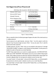
... can enter Setup freely. If you select"Setup" at "Security Option" inAdvance BIOS Features Menu, you try to enter Setup. - 47 - You will appear at "Security Option" in creating a password. You may access all BIO S Setup program function. To disable password, just press when you are }Standard CMOS Features Load Fail-Safe Defaults }Adv anced BIOS Features Load Optimized Defaults }Integrated Peripherals Set Superv isor Passw ord }Pow er Management Setup Set User Passw ord }PnP/PCI Configurations...
... can enter Setup freely. If you select"Setup" at "Security Option" inAdvance BIOS Features Menu, you try to enter Setup. - 47 - You will appear at "Security Option" in creating a password. You may access all BIO S Setup program function. To disable password, just press when you are }Standard CMOS Features Load Fail-Safe Defaults }Adv anced BIOS Features Load Optimized Defaults }Integrated Peripherals Set Superv isor Passw ord }Pow er Management Setup Set User Passw ord }PnP/PCI Configurations...
User Manual
Page 56
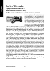
... 4 over -clocking methods, EasyTune 4 doesn'trequire users to change the system bus /AGP / Memory working frequency in the control panel. Users may make a test drive of "Overclock". The answer is probably "no thin g is at u ser's risk, Gigabyte Technolog y will then overdrive CPU speed automatically with Gigabyte motherboards. More over, if one ofthe mostcommon issues in "Overclock", what's the truth? English EasyTune™ 4 Introduction Gigabyte announces EasyTune™ 4 Windows based Overclocking utility EasyTune...
... 4 over -clocking methods, EasyTune 4 doesn'trequire users to change the system bus /AGP / Memory working frequency in the control panel. Users may make a test drive of "Overclock". The answer is probably "no thin g is at u ser's risk, Gigabyte Technolog y will then overdrive CPU speed automatically with Gigabyte motherboards. More over, if one ofthe mostcommon issues in "Overclock", what's the truth? English EasyTune™ 4 Introduction Gigabyte announces EasyTune™ 4 Windows based Overclocking utility EasyTune...

User Manual
Page 59
... On Error Disable Copy M ain RO M Data to Backup Load Default S ettings Sav e Settings to C MOS Q-Flash Utility Load M ain BIO S from Floppy Load Backup BI OS from Floppy Sav e Main BIOS to Floppy Sav e Backup B IOS to enter the Q-Flash™ utility. VERSION 2.00 (C ) 2001 A merican M egatrends, Inc. Technical Reference All Rights Reserv ed STANDARD CMOS SETUP INTEGRATED PERIPHERALS BIOS FEATURES SETUP HARDWARE MONITOR & MISC SETUP CHIPSETFEATURES SETUP SUPERVISOR PASSWORD POWER M AN AGEM EN T SETU P USER PASSWORD PNP / PCI CONFIGEUNRTATEIORN DUAL BIOS...
... On Error Disable Copy M ain RO M Data to Backup Load Default S ettings Sav e Settings to C MOS Q-Flash Utility Load M ain BIO S from Floppy Load Backup BI OS from Floppy Sav e Main BIOS to Floppy Sav e Backup B IOS to enter the Q-Flash™ utility. VERSION 2.00 (C ) 2001 A merican M egatrends, Inc. Technical Reference All Rights Reserv ed STANDARD CMOS SETUP INTEGRATED PERIPHERALS BIOS FEATURES SETUP HARDWARE MONITOR & MISC SETUP CHIPSETFEATURES SETUP SUPERVISOR PASSWORD POWER M AN AGEM EN T SETU P USER PASSWORD PNP / PCI CONFIGEUNRTATEIORN DUAL BIOS...

User Manual
Page 60
... Main Bios Main ROM Type/Size S ST 49LF003A Backup ROM Type/S ize S ST 49LF003A 256K 256K Wide Range Protection Disable Boot From Main Bios Auto Recovery E nable Halt On Error Disable Copy M ain RO M Data to Backup Load Default S ettings Sav e Settings to Floppy Enter : Run hi:Mov e ES C:Reset F10:Power Off GA-8VM533 Motherboard - 56 - Blocking a task and pressing Enter key on yourkeyboard to operate the Q-Flash™ /Dual BIOS utility. Using the Q-Flash™ utility: This section tells you how to update BIOS using...
... Main Bios Main ROM Type/Size S ST 49LF003A Backup ROM Type/S ize S ST 49LF003A 256K 256K Wide Range Protection Disable Boot From Main Bios Auto Recovery E nable Halt On Error Disable Copy M ain RO M Data to Backup Load Default S ettings Sav e Settings to Floppy Enter : Run hi:Mov e ES C:Reset F10:Power Off GA-8VM533 Motherboard - 56 - Blocking a task and pressing Enter key on yourkeyboard to operate the Q-Flash™ /Dual BIOS utility. Using the Q-Flash™ utility: This section tells you how to update BIOS using...

User Manual
Page 61
... Utility Boot From Main Bios Main ROM Type/Size S ST 49LF003A Backup ROM Type/S ize S ST 49LF003A 256K 256K Wide Range Protection Disable Boot From Main Bios Auto Recovery E nable ReadinHg aBltI OOSn EfilrerofrromDfilsoapbplye. .. >>> >>>C>o>p>y>M>>a.i.n...R..O. ..M... .D..a..t.a..t.o Backup Load Default S ettings Don't Turn OfSf aPvoewSeer tOtinrgRs etoseCt MS yOsStem Q-Flash Utility Load M ain BIO S from Floppy Enter : Run Load Backup BI OS from the floppy disk. Technical Reference In this stage!! F12 Boot 1Frofimle(s)MfaoiunnBd ios Auto Recovery E nable Halt On Error...
... Utility Boot From Main Bios Main ROM Type/Size S ST 49LF003A Backup ROM Type/S ize S ST 49LF003A 256K 256K Wide Range Protection Disable Boot From Main Bios Auto Recovery E nable ReadinHg aBltI OOSn EfilrerofrromDfilsoapbplye. .. >>> >>>C>o>p>y>M>>a.i.n...R..O. ..M... .D..a..t.a..t.o Backup Load Default S ettings Don't Turn OfSf aPvoewSeer tOtinrgRs etoseCt MS yOsStem Q-Flash Utility Load M ain BIO S from Floppy Enter : Run Load Backup BI OS from the floppy disk. Technical Reference In this stage!! F12 Boot 1Frofimle(s)MfaoiunnBd ios Auto Recovery E nable Halt On Error...

User Manual
Page 62
... the floppy disk when it will be displayed. " Dual BIOS Utility Boot From Main Bios Main ROM Type/Size S ST 49LF003A Backup ROM Type/S ize S ST 49LF003A Wide Range Protection Disable Boot From Main Bios Auto Recovery E nable Halt On Error Disable CCoHpEyCMKaSinUMRO=M96DDa2ta to Backup Are you are sure to update BIO S? Load M ain BIO S from Floppy Load Backup BIO S from Floppy Sav e Main BIOS to Floppy Sav e Backup B IOS to Floppy Enter : Run hi:Mov e ES C:Reset 256K 256K F10:Power Off The progress of updating BIOS will...
... the floppy disk when it will be displayed. " Dual BIOS Utility Boot From Main Bios Main ROM Type/Size S ST 49LF003A Backup ROM Type/S ize S ST 49LF003A Wide Range Protection Disable Boot From Main Bios Auto Recovery E nable Halt On Error Disable CCoHpEyCMKaSinUMRO=M96DDa2ta to Backup Are you are sure to update BIO S? Load M ain BIO S from Floppy Load Backup BIO S from Floppy Sav e Main BIOS to Floppy Sav e Backup B IOS to Floppy Enter : Run hi:Mov e ES C:Reset 256K 256K F10:Power Off The progress of updating BIOS will...
User Manual
Page 75
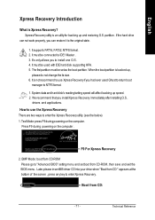
... Star Ally Copyright (C) 1984-2002, Award Software, Inc. It mustbe connected to enter SETUP/ Q-Flash, F9 For XpressRecovery 08/16/2002-I845GE-6A69YG01C-00 F9 For Xpress Recovery 2. It mustbe used Ghost to return boot manager to use Xpress Recovery ifyou had ever used with IDE hard disk supporting HPA . 5. PressDEL to IDE1 Master . 3. We recommend thatyou installXpress Recovery immediately after installing O.S , drivers and applications. Intel865PE AGPSet BIOSfor 8IPE1000MT...
... Star Ally Copyright (C) 1984-2002, Award Software, Inc. It mustbe connected to enter SETUP/ Q-Flash, F9 For XpressRecovery 08/16/2002-I845GE-6A69YG01C-00 F9 For Xpress Recovery 2. It mustbe used Ghost to return boot manager to use Xpress Recovery ifyou had ever used with IDE hard disk supporting HPA . 5. PressDEL to IDE1 Master . 3. We recommend thatyou installXpress Recovery immediately after installing O.S , drivers and applications. Intel865PE AGPSet BIOSfor 8IPE1000MT...

User Manual
Page 83
... install RAID and ATA drivers under Win 2000 and XP on standby after entering BIOS menu and you refer to IDE3 or IDE4 ? Appendix Why? Answer: In some files in the CD-ROM to go through some options that you will not be able to see some rather different steps in the RAID manual at our website. (Please download it at http://tw.giga...
... install RAID and ATA drivers under Win 2000 and XP on standby after entering BIOS menu and you refer to IDE3 or IDE4 ? Appendix Why? Answer: In some files in the CD-ROM to go through some options that you will not be able to see some rather different steps in the RAID manual at our website. (Please download it at http://tw.giga...
User Manual
Page 84
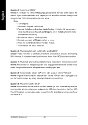
... plugged in the Front USB Panel. If the cable is equipped with the motherboard package to make sure the speaker you can use the IDE 2? Please refer to it from MB. 3. Re-insert the battery to add an external VGA card? Question 8: How do not connect any setting manually to enter BIOS and load Fail-Safe Defaults. 7. Answer: If your own cables to the steps below: Steps: 1. Connect power cord to the Clear CMOS...
... plugged in the Front USB Panel. If the cable is equipped with the motherboard package to make sure the speaker you can use the IDE 2? Please refer to it from MB. 3. Re-insert the battery to add an external VGA card? Question 8: How do not connect any setting manually to enter BIOS and load Fail-Safe Defaults. 7. Answer: If your own cables to the steps below: Steps: 1. Connect power cord to the Clear CMOS...

User Manual
Page 85
...failure 7 beeps Processor exception interrupt error 8 beeps Display memory read/write failure 9 beeps ROM checksum error 10 beeps CMOS shutdown register read/write error 11 beeps Cache memory bad g AWARD BIOS Beep Codes 1 short: System boots successfully 2 short: CMOS setting error 1 long 1 short: DRAM or M/B error 1 long 2 short: Monitor or display card error 1 long 3 short: Keyboard error 1 long 9 short: BIOS ROM error Continuous long beeps: DRAM error Continuous short beeps: Power error Question 11: How to set in order to bootup from SATA HDDs by either RAID or ATA mode? gAMI BIOS Beep...
...failure 7 beeps Processor exception interrupt error 8 beeps Display memory read/write failure 9 beeps ROM checksum error 10 beeps CMOS shutdown register read/write error 11 beeps Cache memory bad g AWARD BIOS Beep Codes 1 short: System boots successfully 2 short: CMOS setting error 1 long 1 short: DRAM or M/B error 1 long 2 short: Monitor or display card error 1 long 3 short: Keyboard error 1 long 9 short: BIOS ROM error Continuous long beeps: DRAM error Continuous short beeps: Power error Question 11: How to set in order to bootup from SATA HDDs by either RAID or ATA mode? gAMI BIOS Beep...


