Manual
Page 2
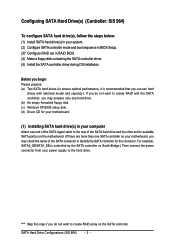
... cable to the rear of the SATA hard drive and the other end to available SATA port(s) on the motherboard. (If there are more than one SATA controller on your motherboard, you may prepare only one hard drive. (b) An empty formatted floppy disk. (c) Windows XP/2000 setup disk... hard drives (to ensure optimal performance, it is controlled by the SATA controller on South-Bridge.) Then connect the power connector from your motherboard. (1) Installing SATA hard drive(s) in RAID BIOS. (4) Make a floppy disk containing the SATA controller driver. (5) Install the SATA controller driver during...
... cable to the rear of the SATA hard drive and the other end to available SATA port(s) on the motherboard. (If there are more than one SATA controller on your motherboard, you may prepare only one hard drive. (b) An empty formatted floppy disk. (c) Windows XP/2000 setup disk... hard drives (to ensure optimal performance, it is controlled by the SATA controller on South-Bridge.) Then connect the power connector from your motherboard. (1) Installing SATA hard drive(s) in RAID BIOS. (4) Make a floppy disk containing the SATA controller driver. (5) Install the SATA controller driver during...
Manual
Page 3
... will see shall depend on your motherboard. In BIOS Setup menu, go to enter BIOS Setup during POST (Power-On Self Test). CMOS Setup Utility-Copyright (C) 1984-2004 Award Software Integrated Peripherals ` ...
... will see shall depend on your motherboard. In BIOS Setup menu, go to enter BIOS Setup during POST (Power-On Self Test). CMOS Setup Utility-Copyright (C) 1984-2004 Award Software Integrated Peripherals ` ...
Manual
Page 10
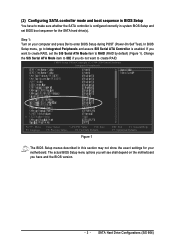
Step 1: Find an available system and insert the motherboard driver CD into the CD-ROM drive. The installation utility will appear automatically. Step 2: Go to copy the driver. The instructions below explain how to ... not be recognized during the Windows setup process. ¤å First of all, you need to copy the driver for the SATA controller from the motherboard driver CD to the BootDrv folder and look for the SATA controller during OS installation. Quit the installation utility first. Ác (4) Making a SATA Driver Disk...
Step 1: Find an available system and insert the motherboard driver CD into the CD-ROM drive. The installation utility will appear automatically. Step 2: Go to copy the driver. The instructions below explain how to ... not be recognized during the Windows setup process. ¤å First of all, you need to copy the driver for the SATA controller from the motherboard driver CD to the BootDrv folder and look for the SATA controller during OS installation. Quit the installation utility first. Ác (4) Making a SATA Driver Disk...
Manual
Page 11
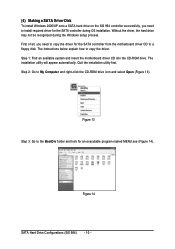
SATA Hard Drive Configurations (SiS 964) An MS-DOS prompt screen similar to the floppy disk. Step 4: Double-click MENU.exe. Then it will take about one minute to copy the SATA driver from the motherboard driver CD to Figure 15 below will appear. Step 6: Press 0 to select D) SiS 964 SATA. Figure 15 Step 5: Insert an empty floppy disk and press D to exit when the procedure is complete (Figure 16). Figure 16 - 11 - You have copied the SATA driver successfully.
SATA Hard Drive Configurations (SiS 964) An MS-DOS prompt screen similar to the floppy disk. Step 4: Double-click MENU.exe. Then it will take about one minute to copy the SATA driver from the motherboard driver CD to Figure 15 below will appear. Step 6: Press 0 to select D) SiS 964 SATA. Figure 15 Step 5: Insert an empty floppy disk and press D to exit when the procedure is complete (Figure 16). Figure 16 - 11 - You have copied the SATA driver successfully.
Manual
Page 13
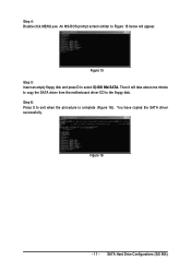
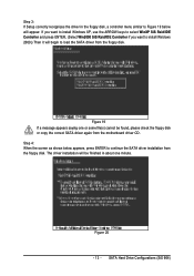
... appear. Step 4: When the screen as shown below will be found, please check the floppy disk or copy the correct SATA driver again from the motherboard driver CD. Figure 20 - 13 -
... appear. Step 4: When the screen as shown below will be found, please check the floppy disk or copy the correct SATA driver again from the motherboard driver CD. Figure 20 - 13 -
Manual
Page 1
GA-8S648FX-775(-C) Intel® Pentium® 4 LGA775 Processor Motherboard User's Manual Rev. 1002 12ME-8S648FXT-1002 * The WEEE marking on the product indicates this product must not be disposed of with user's other household waste and must be handed over to a designated collection point for the recycling of waste electrical and electronic equipment!! * The WEEE marking applies only in European Union's member states.
GA-8S648FX-775(-C) Intel® Pentium® 4 LGA775 Processor Motherboard User's Manual Rev. 1002 12ME-8S648FXT-1002 * The WEEE marking on the product indicates this product must not be disposed of with user's other household waste and must be handed over to a designated collection point for the recycling of waste electrical and electronic equipment!! * The WEEE marking applies only in European Union's member states.
Manual
Page 2
Motherboard GA-8S648FX-775 Nov. 23, 2004 Motherboard GA-8S648FX-775 Nov. 23, 2004
Motherboard GA-8S648FX-775 Nov. 23, 2004 Motherboard GA-8S648FX-775 Nov. 23, 2004
Manual
Page 4
Table of Contents GA-8S648FX-775(-C) Motherboard Layout 6 Block Diagram ...7 Chapter 1 Hardware Installation 9 1-1 Considerations Prior to Installation 9 1-2 Feature Summary 10 1-3 Installation of the CPU and Heatsink 12 1-3-1 Installation of the CPU 12 1-3-2 ...
Table of Contents GA-8S648FX-775(-C) Motherboard Layout 6 Block Diagram ...7 Chapter 1 Hardware Installation 9 1-1 Considerations Prior to Installation 9 1-2 Feature Summary 10 1-3 Installation of the CPU and Heatsink 12 1-3-1 Installation of the CPU 12 1-3-2 ...
Manual
Page 6
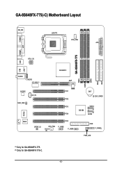
GA-8S648FX-775(-C) Motherboard Layout COMA KB_MS LGA775 CPU_FAN ATX COMB LPT GA-8S648FX-775 DDR1 DDR2 DDR3 IDE2 IDE1 ATX_12V USB LAN (*) USB AUDIO F_AUDIO ICS 1883 (*) SiS 648FX AGP CODEC CD_IN SUR_CEN PCI1 BAT CLR_CMOS PCI2 PCI3 SATA1 SiS 964 PCI4 SATA0 BIOS SPDIF_IO PCI5 SYS_FAN IR F_USB2 F_USB1 FDD F_PANEL PWR_LED (#) -C IT8705 (*) Only for GA-8S648FX-775. (#) Only for GA-8S648FX-775-C. - 6 -
GA-8S648FX-775(-C) Motherboard Layout COMA KB_MS LGA775 CPU_FAN ATX COMB LPT GA-8S648FX-775 DDR1 DDR2 DDR3 IDE2 IDE1 ATX_12V USB LAN (*) USB AUDIO F_AUDIO ICS 1883 (*) SiS 648FX AGP CODEC CD_IN SUR_CEN PCI1 BAT CLR_CMOS PCI2 PCI3 SATA1 SiS 964 PCI4 SATA0 BIOS SPDIF_IO PCI5 SYS_FAN IR F_USB2 F_USB1 FDD F_PANEL PWR_LED (#) -C IT8705 (*) Only for GA-8S648FX-775. (#) Only for GA-8S648FX-775-C. - 6 -
Manual
Page 9
... as a result of uncertified components. 5. Damage due to natural disaster, accident or human cause. 2. Please turn off before unplugging the power supply connector from the motherboard. These stickers are connected. 4. Thus, prior to be an unofficial Gigabyte product. - 9 - Product determined to installation, please follow the instructions below: 1. Turning on the...
... as a result of uncertified components. 5. Damage due to natural disaster, accident or human cause. 2. Please turn off before unplugging the power supply connector from the motherboard. These stickers are connected. 4. Thus, prior to be an unofficial Gigabyte product. - 9 - Product determined to installation, please follow the instructions below: 1. Turning on the...
Manual
Page 10
GA-8S648FX-775(-C) Motherboard - 10 - English 1-2 Feature Summary CPU Chipset Memory Slots IDE Connections FDD Connections Onboard SATA Peripherals Onboard LAN (*) Onboard Audio Š Supports the latest Intel® ... Š Line In / 2 rear speaker(by s/w switch) Š Mic In / center& subwoofer(by s/w switch) Š Supports SPDIF In/Out connection Š CD In (*) Only for GA-8S648FX-775.
GA-8S648FX-775(-C) Motherboard - 10 - English 1-2 Feature Summary CPU Chipset Memory Slots IDE Connections FDD Connections Onboard SATA Peripherals Onboard LAN (*) Onboard Audio Š Supports the latest Intel® ... Š Line In / 2 rear speaker(by s/w switch) Š Mic In / center& subwoofer(by s/w switch) Š Supports SPDIF In/Out connection Š CD In (*) Only for GA-8S648FX-775.
Manual
Page 12
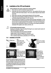
... properly. Fig. 2 Remove the plastic covering on the CPU socket to set beyond the proper specifications, please do so according to the CPU during installation.) GA-8S648FX-775(-C) Motherboard - 12 - Please take note of the one indented corner of the following conditions: 1. HT functionality requirement content : Enabling the functionality of Hyper-Threading Technology for...
... properly. Fig. 2 Remove the plastic covering on the CPU socket to set beyond the proper specifications, please do so according to the CPU during installation.) GA-8S648FX-775(-C) Motherboard - 12 - Please take note of the one indented corner of the following conditions: 1. HT functionality requirement content : Enabling the functionality of Hyper-Threading Technology for...
Manual
Page 13
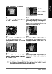
... Female Push Pin Fig.1 Please apply an even layer of heatsink paste on the surface of motherboard after installing. The heatsink may adhere to the CPU fan header located on the motherboard. Hardware Installation Fig. 2 (Turning the push pin along the direction of arrow is to remove... face inwards before installation. (This instruction is complete. If the push pin is inserted as a result of hardening of arrow sign on the motherboard.Pressing down the push pins diagonally. Fig. 4 Please make sure the push pins aim to the heatsink installation section of the user manual) Fig...
... Female Push Pin Fig.1 Please apply an even layer of heatsink paste on the surface of motherboard after installing. The heatsink may adhere to the CPU fan header located on the motherboard. Hardware Installation Fig. 2 (Turning the push pin along the direction of arrow is to remove... face inwards before installation. (This instruction is complete. If the push pin is inserted as a result of hardening of arrow sign on the motherboard.Pressing down the push pins diagonally. Fig. 4 Please make sure the push pins aim to the heatsink installation section of the user manual) Fig...
Manual
Page 14
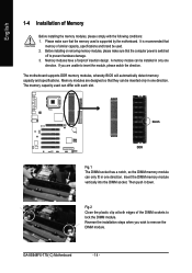
...memory module vertically into the DIMM socket. Then push it down. Please make sure that the memory used is supported by the motherboard. Memory modules have a foolproof insertion design. Memory modules are unable to insert the module, please switch the direction. Fig.2... when you are designed so that memory of similar capacity, specifications and brand be used can be inserted only in only one direction. GA-8S648FX-775(-C) Motherboard - 14 - A memory module can differ with the following conditions: 1. If you wish to remove the DIMM module. English -C ...
...memory module vertically into the DIMM socket. Then push it down. Please make sure that the memory used is supported by the motherboard. Memory modules have a foolproof insertion design. Memory modules are unable to insert the module, please switch the direction. Fig.2... when you are designed so that memory of similar capacity, specifications and brand be used can be inserted only in only one direction. GA-8S648FX-775(-C) Motherboard - 14 - A memory module can differ with the following conditions: 1. If you wish to remove the DIMM module. English -C ...
Manual
Page 15
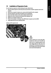
... slot bracket of the AGP slot when you try to the onboard AGP slot and press firmly down on the card are indeed seated in motherboard. 4. Read the related expansion card's instruction document before install the expansion card into expansion slot in the slot. 5. Remove your expansion card by the small...
... slot bracket of the AGP slot when you try to the onboard AGP slot and press firmly down on the card are indeed seated in motherboard. 4. Read the related expansion card's instruction document before install the expansion card into expansion slot in the slot. 5. Remove your expansion card by the small...
Manual
Page 16
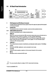
If your OS or device(s) vendors. You can be connected to serial-based mouse or data processing devices. GA-8S648FX-775(-C) Motherboard - 16 - can use audio software to Line In jack. have a standard USB interface. Also make sure your OS supports USB ...(Serial Port) Connects to MIC In jack. For more information please contact your OS does not support USB controller, please contact OS vendor for GA-8S648FX-775. Line Out Connect the stereo speakers, earphone or front surround channels to the lower port (purple). channel audio functioning. (*) Only for possible ...
If your OS or device(s) vendors. You can be connected to serial-based mouse or data processing devices. GA-8S648FX-775(-C) Motherboard - 16 - can use audio software to Line In jack. have a standard USB interface. Also make sure your OS supports USB ...(Serial Port) Connects to MIC In jack. For more information please contact your OS does not support USB controller, please contact OS vendor for GA-8S648FX-775. Line Out Connect the stereo speakers, earphone or front surround channels to the lower port (purple). channel audio functioning. (*) Only for possible ...
Manual
Page 18
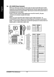
Before connecting the power connector, please make sure that all the components on the motherboard and connect tightly. If the ATX_12V power connector is not connected, the system will not start . 42 31 Pin... +12V Pin No. If a power supply is used (300W or greater). Align the power connector with its proper location on the motherboard. Please use of the power connector, the power supply can lead to an unstable system or a system that is unable to the ...GND 14 PS_ON(softOn/Off) 15 GND 16 GND 17 GND 18 -5V 19 VCC 20 VCC GA-8S648FX-775(-C) Motherboard - 18 -
Before connecting the power connector, please make sure that all the components on the motherboard and connect tightly. If the ATX_12V power connector is not connected, the system will not start . 42 31 Pin... +12V Pin No. If a power supply is used (300W or greater). Align the power connector with its proper location on the motherboard. Please use of the power connector, the power supply can lead to an unstable system or a system that is unable to the ...GND 14 PS_ON(softOn/Off) 15 GND 16 GND 17 GND 18 -5V 19 VCC 20 VCC GA-8S648FX-775(-C) Motherboard - 18 -
Manual
Page 20
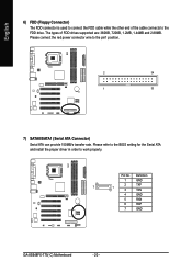
... BIOS setting for the Serial ATA and install the proper driver in order to the FDD drive. Definition 1 GND 7 2 TXP 1 3 TXN 4 GND 5 RXN 6 RXP 7 GND -C GA-8S648FX-775(-C) Motherboard - 20 - Please connect the red power connector wire to the pin1 position. 2 34 1 33 -C 7) SATA0/SATA1 (Serial ATA Connector) Serial ATA can provide 150MB/s transfer...
... BIOS setting for the Serial ATA and install the proper driver in order to the FDD drive. Definition 1 GND 7 2 TXP 1 3 TXN 4 GND 5 RXN 6 RXP 7 GND -C GA-8S648FX-775(-C) Motherboard - 20 - Please connect the red power connector wire to the pin1 position. 2 34 1 33 -C 7) SATA0/SATA1 (Serial ATA Connector) Serial ATA can provide 150MB/s transfer...
Manual
Page 22
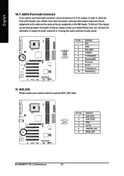
... FrontAudio (L) RearAudio(L) -C 11) SUR_CEN Please contact your nearest dealer for optional SUR_CEN cable. 6 5 2 1 Pin No. 1 2 3 4 5 6 Definition SUR OUTL SUR OUTR GND No Pin CENTER_OUT BASS_OUT -C GA-8S648FX-775(-C) Motherboard - 22 - To find out if the chassis you are the same as the pin assigments on the MB header. English 10) F_AUDIO (Front Audio Connector...
... FrontAudio (L) RearAudio(L) -C 11) SUR_CEN Please contact your nearest dealer for optional SUR_CEN cable. 6 5 2 1 Pin No. 1 2 3 4 5 6 Definition SUR OUTL SUR OUTR GND No Pin CENTER_OUT BASS_OUT -C GA-8S648FX-775(-C) Motherboard - 22 - To find out if the chassis you are the same as the pin assigments on the MB header. English 10) F_AUDIO (Front Audio Connector...
Manual
Page 24
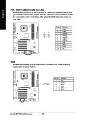
... damage it. For optional front USB cable, please contact your nearest dealer for optional IR device. Definition 1 VCC 2 No Pin 1 3 IR RX 4 GND 5 IR TX -C GA-8S648FX-775(-C) Motherboard - 24 - Pin No. English 14) F_ USB1 / F_USB2 (Front USB Connector) Be careful with the polarity of the front USB connector. Check the pin assignment...
... damage it. For optional front USB cable, please contact your nearest dealer for optional IR device. Definition 1 VCC 2 No Pin 1 3 IR RX 4 GND 5 IR TX -C GA-8S648FX-775(-C) Motherboard - 24 - Pin No. English 14) F_ USB1 / F_USB2 (Front USB Connector) Be careful with the polarity of the front USB connector. Check the pin assignment...


