Manual
Page 2
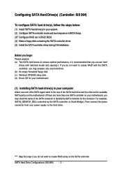
... in your computer Attach one end of the SATA signal cable to the rear of the SATA connector to identify the SATA controller for your motherboard. (1) Installing SATA hard drive(s) in RAID BIOS. (4) Make a floppy disk containing the SATA controller driver. (5) Install the SATA controller driver during ...SATA hard drives (to ensure optimal performance, it is controlled by the SATA controller on South-Bridge.) Then connect the power connector from your motherboard, you do not want to create RAID with identical model and capacity). "*" Skip this step if you may check the name of the ...
... in your computer Attach one end of the SATA signal cable to the rear of the SATA connector to identify the SATA controller for your motherboard. (1) Installing SATA hard drive(s) in RAID BIOS. (4) Make a floppy disk containing the SATA controller driver. (5) Install the SATA controller driver during ...SATA hard drives (to ensure optimal performance, it is controlled by the SATA controller on South-Bridge.) Then connect the power connector from your motherboard, you do not want to create RAID with identical model and capacity). "*" Skip this step if you may check the name of the ...
Manual
Page 3
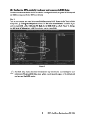
... Setup and set the SiS Serial ATA Mode item to create RAID. If you want to RAID (RAID by default) (Figure 1). Step 1: Turn on the motherboard you do not want to create RAID, set BIOS boot sequence for your computer and press Del to make sure whether the SATA controller is... enabled. The actual BIOS Setup menu options you will see shall depend on your motherboard. Change the SiS Serial ATA Mode item to IDE if you have to enter BIOS Setup during POST (Power-On Self Test). (2) Configuring SATA controller...
... Setup and set the SiS Serial ATA Mode item to create RAID. If you want to RAID (RAID by default) (Figure 1). Step 1: Turn on the motherboard you do not want to create RAID, set BIOS boot sequence for your computer and press Del to make sure whether the SATA controller is... enabled. The actual BIOS Setup menu options you will see shall depend on your motherboard. Change the SiS Serial ATA Mode item to IDE if you have to enter BIOS Setup during POST (Power-On Self Test). (2) Configuring SATA controller...
Manual
Page 10
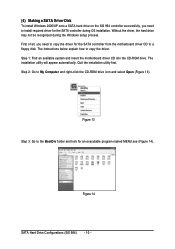
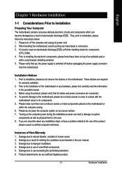
Step 1: Find an available system and insert the motherboard driver CD into the CD-ROM drive. The instructions below explain how to My Computer and right-click the CD-ROM drive icon and select ... the SATA controller during the Windows setup process. ¤å First of all, you need to copy the driver for the SATA controller from the motherboard driver CD to a floppy disk. Quit the installation utility first. Figure 14 SATA Hard Drive Configurations (SiS 964) - 10 -
Step 1: Find an available system and insert the motherboard driver CD into the CD-ROM drive. The instructions below explain how to My Computer and right-click the CD-ROM drive icon and select ... the SATA controller during the Windows setup process. ¤å First of all, you need to copy the driver for the SATA controller from the motherboard driver CD to a floppy disk. Quit the installation utility first. Figure 14 SATA Hard Drive Configurations (SiS 964) - 10 -
Manual
Page 11
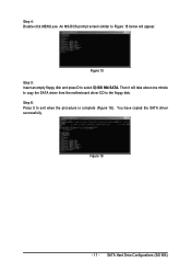
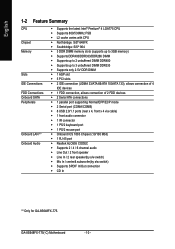
Then it will appear. You have copied the SATA driver successfully. Figure 16 - 11 - SATA Hard Drive Configurations (SiS 964) Figure 15 Step 5: Insert an empty floppy disk and press D to exit when the procedure is complete (Figure 16). Step 6: Press 0 to select D) SiS 964 SATA. An MS-DOS prompt screen similar to Figure 15 below will take about one minute to copy the SATA driver from the motherboard driver CD to the floppy disk. Step 4: Double-click MENU.exe.
Then it will appear. You have copied the SATA driver successfully. Figure 16 - 11 - SATA Hard Drive Configurations (SiS 964) Figure 15 Step 5: Insert an empty floppy disk and press D to exit when the procedure is complete (Figure 16). Step 6: Press 0 to select D) SiS 964 SATA. An MS-DOS prompt screen similar to Figure 15 below will take about one minute to copy the SATA driver from the motherboard driver CD to the floppy disk. Step 4: Double-click MENU.exe.
Manual
Page 13
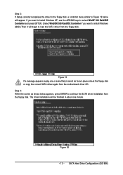
...(s) cannot be finished in the floppy disk, a controller menu similar to Figure 19 below appears, press ENTER to continue the SATA driver installation from the motherboard driver CD. SATA Hard Drive Configurations (SiS 964) Step 3: If Setup correctly recognizes the driver in about one minute. Step 4: When the screen as shown...
...(s) cannot be finished in the floppy disk, a controller menu similar to Figure 19 below appears, press ENTER to continue the SATA driver installation from the motherboard driver CD. SATA Hard Drive Configurations (SiS 964) Step 3: If Setup correctly recognizes the driver in about one minute. Step 4: When the screen as shown...
Manual
Page 1
GA-8S648FX-775(-C) Intel® Pentium® 4 LGA775 Processor Motherboard User's Manual Rev. 1002 12ME-8S648FXT-1002 * The WEEE marking on the product indicates this product must not be disposed of with user's other household waste and must be handed over to a designated collection point for the recycling of waste electrical and electronic equipment!! * The WEEE marking applies only in European Union's member states.
GA-8S648FX-775(-C) Intel® Pentium® 4 LGA775 Processor Motherboard User's Manual Rev. 1002 12ME-8S648FXT-1002 * The WEEE marking on the product indicates this product must not be disposed of with user's other household waste and must be handed over to a designated collection point for the recycling of waste electrical and electronic equipment!! * The WEEE marking applies only in European Union's member states.
Manual
Page 2
Motherboard GA-8S648FX-775 Nov. 23, 2004 Motherboard GA-8S648FX-775 Nov. 23, 2004
Motherboard GA-8S648FX-775 Nov. 23, 2004 Motherboard GA-8S648FX-775 Nov. 23, 2004
Manual
Page 4
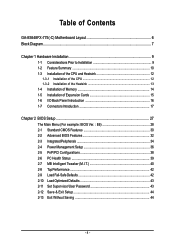
Table of Contents GA-8S648FX-775(-C) Motherboard Layout 6 Block Diagram ...7 Chapter 1 Hardware Installation 9 1-1 Considerations Prior to Installation 9 1-2 Feature Summary 10 1-3 Installation of the CPU and Heatsink 12 1-3-1 Installation of the CPU 12 1-3-2 ...
Table of Contents GA-8S648FX-775(-C) Motherboard Layout 6 Block Diagram ...7 Chapter 1 Hardware Installation 9 1-1 Considerations Prior to Installation 9 1-2 Feature Summary 10 1-3 Installation of the CPU and Heatsink 12 1-3-1 Installation of the CPU 12 1-3-2 ...
Manual
Page 6
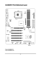
GA-8S648FX-775(-C) Motherboard Layout COMA KB_MS LGA775 CPU_FAN ATX COMB LPT GA-8S648FX-775 DDR1 DDR2 DDR3 IDE2 IDE1 ATX_12V USB LAN (*) USB AUDIO F_AUDIO ICS 1883 (*) SiS 648FX AGP CODEC CD_IN SUR_CEN PCI1 BAT CLR_CMOS PCI2 PCI3 SATA1 SiS 964 PCI4 SATA0 BIOS SPDIF_IO PCI5 SYS_FAN IR F_USB2 F_USB1 FDD F_PANEL PWR_LED (#) -C IT8705 (*) Only for GA-8S648FX-775. (#) Only for GA-8S648FX-775-C. - 6 -
GA-8S648FX-775(-C) Motherboard Layout COMA KB_MS LGA775 CPU_FAN ATX COMB LPT GA-8S648FX-775 DDR1 DDR2 DDR3 IDE2 IDE1 ATX_12V USB LAN (*) USB AUDIO F_AUDIO ICS 1883 (*) SiS 648FX AGP CODEC CD_IN SUR_CEN PCI1 BAT CLR_CMOS PCI2 PCI3 SATA1 SiS 964 PCI4 SATA0 BIOS SPDIF_IO PCI5 SYS_FAN IR F_USB2 F_USB1 FDD F_PANEL PWR_LED (#) -C IT8705 (*) Only for GA-8S648FX-775. (#) Only for GA-8S648FX-775-C. - 6 -
Manual
Page 9
... do not allow screws to be an unofficial Gigabyte product. - 9 - Please do not remove the stickers on the motherboard or within a electrostatic shielding container. 5. If you the power supply is best to installing the electronic components, please ... 4. Installation Notices 1. Damage due to natural disaster, accident or human cause. 2. Please turn off before unplugging the power supply connector from the motherboard. Damage due to improper installation. 4. Prior to wear an electrostatic discharge (ESD) cuff when handling electronic components (CPU, RAM). 4. Before using...
... do not allow screws to be an unofficial Gigabyte product. - 9 - Please do not remove the stickers on the motherboard or within a electrostatic shielding container. 5. If you the power supply is best to installing the electronic components, please ... 4. Installation Notices 1. Damage due to natural disaster, accident or human cause. 2. Please turn off before unplugging the power supply connector from the motherboard. Damage due to improper installation. 4. Prior to wear an electrostatic discharge (ESD) cuff when handling electronic components (CPU, RAM). 4. Before using...
Manual
Page 10
... Š Line In / 2 rear speaker(by s/w switch) Š Mic In / center& subwoofer(by s/w switch) Š Supports SPDIF In/Out connection Š CD In (*) Only for GA-8S648FX-775. GA-8S648FX-775(-C) Motherboard - 10 -
... Š Line In / 2 rear speaker(by s/w switch) Š Mic In / center& subwoofer(by s/w switch) Š Supports SPDIF In/Out connection Š CD In (*) Only for GA-8S648FX-775. GA-8S648FX-775(-C) Motherboard - 10 -
Manual
Page 12
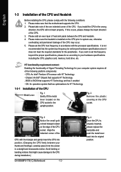
...Technology 1-3-1 Installation of the CPU Metal Lever Fig. 1 Gently lift the metal lever located on the CPU prior to the CPU during installation.) GA-8S648FX-775(-C) Motherboard - 12 - If you install the CPU in the wrong direction, the CPU will not insert properly. Chipset: An SiS® Chipset ... and heatsink. 4. Fig. 3 Notice the small gold colored triangle located on the CPU socket. Avoid twisting or bending motions that the motherboard supports the CPU. 2. If this occurs, please change the insert direction of the CPU and Heatsink Before installing the CPU, please comply ...
...Technology 1-3-1 Installation of the CPU Metal Lever Fig. 1 Gently lift the metal lever located on the CPU prior to the CPU during installation.) GA-8S648FX-775(-C) Motherboard - 12 - If you install the CPU in the wrong direction, the CPU will not insert properly. Chipset: An SiS® Chipset ... and heatsink. 4. Fig. 3 Notice the small gold colored triangle located on the CPU socket. Avoid twisting or bending motions that the motherboard supports the CPU. 2. If this occurs, please change the insert direction of the CPU and Heatsink Before installing the CPU, please comply ...
Manual
Page 13
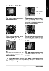
... Male Push Pin The top of Female Push Pin Female Push Pin Fig.1 Please apply an even layer of heatsink paste on the surface of motherboard after installing. Fig. 2 (Turning the push pin along the direction of arrow is to remove the heatsink, on the contrary, is to install.) ... is suggested that either thermal tape rather than heat sink paste be used for detailed installation instructions, please refer to the pin hole on the motherboard.Pressing down the push pins diagonally. Fig. 4 Please make sure the push pins aim to the heatsink installation section of the user manual) Fig. 5...
... Male Push Pin The top of Female Push Pin Female Push Pin Fig.1 Please apply an even layer of heatsink paste on the surface of motherboard after installing. Fig. 2 (Turning the push pin along the direction of arrow is to remove the heatsink, on the contrary, is to install.) ... is suggested that either thermal tape rather than heat sink paste be used for detailed installation instructions, please refer to the pin hole on the motherboard.Pressing down the push pins diagonally. Fig. 4 Please make sure the push pins aim to the heatsink installation section of the user manual) Fig. 5...
Manual
Page 14
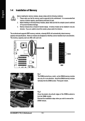
...socket. If you wish to insert the module, please switch the direction. Memory modules have a foolproof insertion design. The motherboard supports DDR memory modules, whereby BIOS will automatically detect memory capacity and specifications. A memory module can only fit in only... clip at both edges of the DIMM sockets to prevent hardware damage. 3. Memory modules are unable to remove the DIMM module. GA-8S648FX-775(-C) Motherboard - 14 - English -C 1-4 Installation of Memory Before installing the memory modules, please comply with each slot. Before installing or ...
...socket. If you wish to insert the module, please switch the direction. Memory modules have a foolproof insertion design. The motherboard supports DDR memory modules, whereby BIOS will automatically detect memory capacity and specifications. A memory module can only fit in only... clip at both edges of the DIMM sockets to prevent hardware damage. 3. Memory modules are unable to remove the DIMM module. GA-8S648FX-775(-C) Motherboard - 14 - English -C 1-4 Installation of Memory Before installing the memory modules, please comply with each slot. Before installing or ...
Manual
Page 15
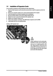
... cover, screws and slot bracket from the operating system. Power on the slot. Be sure the metal contacts on the card are indeed seated in motherboard. 4. Replace your VGA card is locked by following the steps outlined below: 1. Installing a AGP expansion card: Please carefully pull out the small whitedrawable bar at...
... cover, screws and slot bracket from the operating system. Power on the slot. Be sure the metal contacts on the card are indeed seated in motherboard. 4. Replace your VGA card is locked by following the steps outlined below: 1. Installing a AGP expansion card: Please carefully pull out the small whitedrawable bar at...
Manual
Page 16
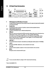
...transfer speeds of a printer, scanner and other peripheral devices. / COM A/COM B (Serial Port) Connects to Line In jack. GA-8S648FX-775(-C) Motherboard - 16 - have a standard USB interface. can be connected to configure 2-/4-/6- For more information please contact your OS does not support... USB controller, please contact OS vendor for GA-8S648FX-775. channel audio functioning. (*) Only for possible patch or driver upgrade. MIC In Microphone can use audio software to MIC ...
...transfer speeds of a printer, scanner and other peripheral devices. / COM A/COM B (Serial Port) Connects to Line In jack. GA-8S648FX-775(-C) Motherboard - 16 - have a standard USB interface. can be connected to configure 2-/4-/6- For more information please contact your OS does not support... USB controller, please contact OS vendor for GA-8S648FX-775. channel audio functioning. (*) Only for possible patch or driver upgrade. MIC In Microphone can use audio software to MIC ...
Manual
Page 18
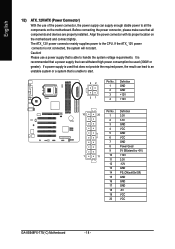
...) 1 11 10 +12V 11 3.3V 12 -12V 13 GND 14 PS_ON(softOn/Off) 15 GND 16 GND 17 GND 18 -5V 19 VCC 20 VCC GA-8S648FX-775(-C) Motherboard - 18 - If a power supply is not connected, the system will not start . 42 31 Pin No. 1 2 3 4 Definition GND GND +12V +...12V Pin No. English -C 1/2) ATX_12V/ATX (Power Connector) With the use a power supply that all the components on the motherboard and connect tightly. It is recommended that a power supply that is able to start . Before connecting the power connector, please make sure that is unable...
...) 1 11 10 +12V 11 3.3V 12 -12V 13 GND 14 PS_ON(softOn/Off) 15 GND 16 GND 17 GND 18 -5V 19 VCC 20 VCC GA-8S648FX-775(-C) Motherboard - 18 - If a power supply is not connected, the system will not start . 42 31 Pin No. 1 2 3 4 Definition GND GND +12V +...12V Pin No. English -C 1/2) ATX_12V/ATX (Power Connector) With the use a power supply that all the components on the motherboard and connect tightly. It is recommended that a power supply that is able to start . Before connecting the power connector, please make sure that is unable...
Manual
Page 20
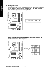
... can provide 150MB/s transfer rate. Please connect the red power connector wire to work properly. Pin No. Definition 1 GND 7 2 TXP 1 3 TXN 4 GND 5 RXN 6 RXP 7 GND -C GA-8S648FX-775(-C) Motherboard - 20 - English 6) FDD (Floppy Connector) The FDD connector is used to connect the FDD cable while the other end of FDD drives supported are: 360KB...
... can provide 150MB/s transfer rate. Please connect the red power connector wire to work properly. Pin No. Definition 1 GND 7 2 TXP 1 3 TXN 4 GND 5 RXN 6 RXP 7 GND -C GA-8S648FX-775(-C) Motherboard - 20 - English 6) FDD (Floppy Connector) The FDD connector is used to connect the FDD cable while the other end of FDD drives supported are: 360KB...
Manual
Page 22
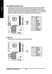
... to utilize the front audio header, your nearest dealer for optional SUR_CEN cable. 6 5 2 1 Pin No. 1 2 3 4 5 6 Definition SUR OUTL SUR OUTR GND No Pin CENTER_OUT BASS_OUT -C GA-8S648FX-775(-C) Motherboard - 22 - In order to play sound. 10 9 2 1 Pin No. 1 2 3 4 5 6 7 8 9 10 Definition MIC GND MIC_BIAS POWER FrontAudio(R) RearAudio(R) Reserved No Pin FrontAudio (L) RearAudio(L) -C 11) SUR_CEN Please...
... to utilize the front audio header, your nearest dealer for optional SUR_CEN cable. 6 5 2 1 Pin No. 1 2 3 4 5 6 Definition SUR OUTL SUR OUTR GND No Pin CENTER_OUT BASS_OUT -C GA-8S648FX-775(-C) Motherboard - 22 - In order to play sound. 10 9 2 1 Pin No. 1 2 3 4 5 6 7 8 9 10 Definition MIC GND MIC_BIAS POWER FrontAudio(R) RearAudio(R) Reserved No Pin FrontAudio (L) RearAudio(L) -C 11) SUR_CEN Please...
Manual
Page 24
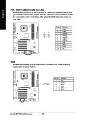
For optional front USB cable, please contact your nearest dealer for optional IR device. Definition 1 VCC 2 No Pin 1 3 IR RX 4 GND 5 IR TX -C GA-8S648FX-775(-C) Motherboard - 24 - Check the pin assignment carefully while you connect the IR. Pin No. Please contact your local dealer. 2 10 1 9 Pin No. 1 2 3 4 5 6 7 8 9 10 Definition Power Power ...
For optional front USB cable, please contact your nearest dealer for optional IR device. Definition 1 VCC 2 No Pin 1 3 IR RX 4 GND 5 IR TX -C GA-8S648FX-775(-C) Motherboard - 24 - Check the pin assignment carefully while you connect the IR. Pin No. Please contact your local dealer. 2 10 1 9 Pin No. 1 2 3 4 5 6 7 8 9 10 Definition Power Power ...


