Manual
Page 7
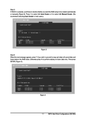
Then press ENTER (Figure 9). Otherwise press N to perform striping on future data only. Figure 9 - 7 - Press 1 to select Auto Create or 2 to select Manual Create. (We recommend selecting Auto Create to most users.) Figure 8 Step 6: When the next message appears, press Y if you want the RAID array to be created automatically or manually (Figure 8). Step 5: If RAID 0 is selected, you'll have to decide whether you wish to proceed to map and stripe all current data and future data to the RAID disks. SATA Hard Drive Configurations (SiS 964)
Then press ENTER (Figure 9). Otherwise press N to perform striping on future data only. Figure 9 - 7 - Press 1 to select Auto Create or 2 to select Manual Create. (We recommend selecting Auto Create to most users.) Figure 8 Step 6: When the next message appears, press Y if you want the RAID array to be created automatically or manually (Figure 8). Step 5: If RAID 0 is selected, you'll have to decide whether you wish to proceed to map and stripe all current data and future data to the RAID disks. SATA Hard Drive Configurations (SiS 964)
Manual
Page 1
GA-8S648FX-775(-C) Intel® Pentium® 4 LGA775 Processor Motherboard User's Manual Rev. 1002 12ME-8S648FXT-1002 * The WEEE marking on the product indicates this product must not be disposed of with user's other household waste and must be handed over to a designated collection point for the recycling of waste electrical and electronic equipment!! * The WEEE marking applies only in European Union's member states.
GA-8S648FX-775(-C) Intel® Pentium® 4 LGA775 Processor Motherboard User's Manual Rev. 1002 12ME-8S648FXT-1002 * The WEEE marking on the product indicates this product must not be disposed of with user's other household waste and must be handed over to a designated collection point for the recycling of waste electrical and electronic equipment!! * The WEEE marking applies only in European Union's member states.
Manual
Page 3
... carefully read the "Product User Manual". „ For detailed information related to Gigabyte's unique features, please go to "Technology Guide" section on Gigabyte's website to their respective companies. No part of this product, Gigabyte has categorized the user manual in the use of Gigabyte. Fore more product details, please click onto Gigabyte's website at www.gigabyte.com.tw Specifications and...
... carefully read the "Product User Manual". „ For detailed information related to Gigabyte's unique features, please go to "Technology Guide" section on Gigabyte's website to their respective companies. No part of this product, Gigabyte has categorized the user manual in the use of Gigabyte. Fore more product details, please click onto Gigabyte's website at www.gigabyte.com.tw Specifications and...
Manual
Page 9
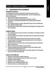
...installation process can become damaged as a result of the motherboard or any hardware, please first carefully read the information in the provided manual. 3. Prior to the installation of electrostatic discharge (ESD). Please make sure there are connected. 4. English Chapter 1 Hardware Installation...as well as physical harm to the user. 8. Instances of uncertified components. 5. Damage due to come in the user manual. 3. Hardware Installation Please do not allow screws to use of Non-Warranty 1. Thus, prior to be an unofficial Gigabyte product. - 9 - Please turn off...
...installation process can become damaged as a result of the motherboard or any hardware, please first carefully read the information in the provided manual. 3. Prior to the installation of electrostatic discharge (ESD). Please make sure there are connected. 4. English Chapter 1 Hardware Installation...as well as physical harm to the user. 8. Instances of uncertified components. 5. Damage due to come in the user manual. 3. Hardware Installation Please do not allow screws to use of Non-Warranty 1. Thus, prior to be an unofficial Gigabyte product. - 9 - Please turn off...
Manual
Page 13
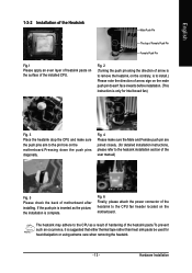
... suggested that either thermal tape rather than heat sink paste be used for detailed installation instructions, please refer to the heatsink installation section of the user manual) Fig. 5 Please check the back of the heatsink to the CPU as the picture, the installation is only for Intel boxed fan) Fig. 3 Place the...
... suggested that either thermal tape rather than heat sink paste be used for detailed installation instructions, please refer to the heatsink installation section of the user manual) Fig. 5 Please check the back of the heatsink to the CPU as the picture, the installation is only for Intel boxed fan) Fig. 3 Place the...
Manual
Page 30
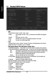
...The year, from Sun. The time is determined by the BIOS and displayed only. IDE Channel 0/Channel 1 Master(Slave) setup You can manually input the correct settings Access Mode Use this if no IDE devices are : CHS/LBA/Large/Auto (Default:Auto) Capacity Capacity of currently...allowed in the month) < Ye a r > 1999 to set the access mode for faster system start up. For example, 1 p.m. Jan. Manual User can use one of sectors GA-8S648FX-775(-C) Motherboard - 30 - English 2-1 Standard CMOS Features Date (mm:dd:yy) Time (hh:mm:ss) CMOS Setup Utility-Copyright (C) 1984-2004 ...
...The year, from Sun. The time is determined by the BIOS and displayed only. IDE Channel 0/Channel 1 Master(Slave) setup You can manually input the correct settings Access Mode Use this if no IDE devices are : CHS/LBA/Large/Auto (Default:Auto) Capacity Capacity of currently...allowed in the month) < Ye a r > 1999 to set the access mode for faster system start up. For example, 1 p.m. Jan. Manual User can use one of sectors GA-8S648FX-775(-C) Motherboard - 30 - English 2-1 Standard CMOS Features Date (mm:dd:yy) Time (hh:mm:ss) CMOS Setup Utility-Copyright (C) 1984-2004 ...
Manual
Page 40
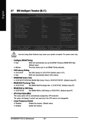
...3T/2T/4T/5T. (Default value:5T) CPU Clock Ratio (MHz) This setup option will automatically set up the DRAM Timing by manual Warning: Wrong DRAM Timing may cause your system corrupted. Clear CMOS to overcome wrong Timing issue KLJI: Move Enter: Select F5: Previous ...detect CAS Latency. CAS Latency Setting 2T/2.5T/3T Set CAS Latency to 2T/2.5T/3T (Default value is not changeable. GA-8S648FX-775(-C) Motherboard - 40 - For power users only. Linear Frequency Control Disabled Disable this function. (Default value) Enabled Enable this function. Auto BIOS will display "Locked"...
...3T/2T/4T/5T. (Default value:5T) CPU Clock Ratio (MHz) This setup option will automatically set up the DRAM Timing by manual Warning: Wrong DRAM Timing may cause your system corrupted. Clear CMOS to overcome wrong Timing issue KLJI: Move Enter: Select F5: Previous ...detect CAS Latency. CAS Latency Setting 2T/2.5T/3T Set CAS Latency to 2T/2.5T/3T (Default value is not changeable. GA-8S648FX-775(-C) Motherboard - 40 - For power users only. Linear Frequency Control Disabled Disable this function. (Default value) Enabled Enable this function. Auto BIOS will display "Locked"...
Manual
Page 41
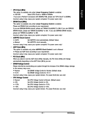
...use DDR333 DRAM module, please set "DRAM Clock(MHz)" to set the AGP Clock (MHz) manually, the PCI Clock (MHz) will change automatically depending on the AGP Clock (MHz) you set. For power End-User use only! - 41 - CPU Voltage Control Normal Set CPU Voltage Control to Normal. (Default ...value) +5% Set CPU Voltage Control to +5%. +7.5% Set CPU Voltage Control to +7.5%. +10% Set CPU Voltage Control to Manual. For power users only! AGP Clock (MHz) This option is available only when AGP/PCI Clock Control is set "DRAM Clock(MHz)" to +0.1V. Normal +0.1V...
...use DDR333 DRAM module, please set "DRAM Clock(MHz)" to set the AGP Clock (MHz) manually, the PCI Clock (MHz) will change automatically depending on the AGP Clock (MHz) you set. For power End-User use only! - 41 - CPU Voltage Control Normal Set CPU Voltage Control to Normal. (Default ...value) +5% Set CPU Voltage Control to +5%. +7.5% Set CPU Voltage Control to +7.5%. +10% Set CPU Voltage Control to Manual. For power users only! AGP Clock (MHz) This option is available only when AGP/PCI Clock Control is set "DRAM Clock(MHz)" to +0.1V. Normal +0.1V...


