Manual
Page 3
...is 1.0. Copyright © 2010 GIGA-BYTE TECHNOLOGY CO., LTD. All rights reserved. For instructions on your motherboard revision before updating motherboard BIOS, drivers, or when looking for technical information. No part of the product, read the User's Manual. For example, "REV: 1.0"... Support&Downloads\Motherboard\Technology Guide page on our website. For product-related information, check on our website at: http://www.gigabyte.com.tw Identifying Your Motherboard Revision The revision number on how to their respective owners. Example: For detailed product information,...
...is 1.0. Copyright © 2010 GIGA-BYTE TECHNOLOGY CO., LTD. All rights reserved. For instructions on your motherboard revision before updating motherboard BIOS, drivers, or when looking for technical information. No part of the product, read the User's Manual. For example, "REV: 1.0"... Support&Downloads\Motherboard\Technology Guide page on our website. For product-related information, check on our website at: http://www.gigabyte.com.tw Identifying Your Motherboard Revision The revision number on how to their respective owners. Example: For detailed product information,...
Manual
Page 4
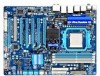
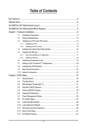
Table of Contents Box Contents...6 Optional Items...6 GA-890FXA-UD7 Motherboard Layout 7 GA-890FXA-UD7 Motherboard Block Diagram 8 Chapter 1 Hardware Installation 9 1-1 Installation Precautions 9 1-2 Product Specifications 10 1-3 Installing the CPU and CPU Cooler ... SATA Bracket 21 1-9 Back Panel Connectors 22 1-10 Internal Connectors 24 Chapter 2 BIOS Setup 37 2-1 Startup Screen 38 2-2 The Main Menu 39 2-3 MB Intelligent Tweaker(M.I.T 41 2-4 Standard CMOS Features 47 2-5 Advanced BIOS Features 49 2-6 Integrated Peripherals 51 2-7 Power Management Setup 55 2-8 PC Health Status...
Table of Contents Box Contents...6 Optional Items...6 GA-890FXA-UD7 Motherboard Layout 7 GA-890FXA-UD7 Motherboard Block Diagram 8 Chapter 1 Hardware Installation 9 1-1 Installation Precautions 9 1-2 Product Specifications 10 1-3 Installing the CPU and CPU Cooler ... SATA Bracket 21 1-9 Back Panel Connectors 22 1-10 Internal Connectors 24 Chapter 2 BIOS Setup 37 2-1 Startup Screen 38 2-2 The Main Menu 39 2-3 MB Intelligent Tweaker(M.I.T 41 2-4 Standard CMOS Features 47 2-5 Advanced BIOS Features 49 2-6 Integrated Peripherals 51 2-7 Power Management Setup 55 2-8 PC Health Status...
Manual
Page 5
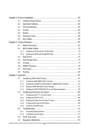
...Utilities...66 Chapter 4 Unique Features 67 4-1 Xpress Recovery2 67 4-2 BIOS Update Utilities 70 4-2-1 Updating the BIOS with the Q-Flash Utility 70 4-2-2 Updating the BIOS with the @BIOS Utility 73 4-3 EasyTune 6...74 4-4 Easy Energy Saver 75 4-5 ...Q-Share...77 4-6 SMART Recovery 78 4-7 Auto Green...79 4-8 Teaming ...80 Chapter 5 Appendix...81 5-1 Configuring SATA Hard Drive(s 81 5-1-1 Configuring AMD SB850 SATA Controller 81 5-1-2 Configuring GIGABYTE...
...Utilities...66 Chapter 4 Unique Features 67 4-1 Xpress Recovery2 67 4-2 BIOS Update Utilities 70 4-2-1 Updating the BIOS with the Q-Flash Utility 70 4-2-2 Updating the BIOS with the @BIOS Utility 73 4-3 EasyTune 6...74 4-4 Easy Energy Saver 75 4-5 ...Q-Share...77 4-6 SMART Recovery 78 4-7 Auto Green...79 4-8 Teaming ...80 Chapter 5 Appendix...81 5-1 Configuring SATA Hard Drive(s 81 5-1-1 Configuring AMD SB850 SATA Controller 81 5-1-2 Configuring GIGABYTE...
Manual
Page 8
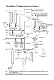
TSB43AB23 AMD SB850 CODEC Dual BIOS 6 SATA 6Gb/s LPC Bus iTE IT8720 Floppy LPT Port COM Port 3 IEEE 1394a ... and install them in the DDR3_3 and DDR3_4 memory sockets. (Note 2) Two share the same ports with eSATA. - 8 - GA-890FXA-UD7 Motherboard Block Diagram 4 PCI Express x8 2 PCI Express x16 1 PCI Express x4 or PCIe CLK (100 MHz) PCI Express x8... Transport 3.0 1 PCI Express x4 AMD 890FX 1 PCI Express x1 or 2 SATA 3Gb/s ATA-133/100/66/ 33 IDE Channel GIGABYTE x4 x1 SATA2 Switch PCIe CLK (100 MHz) 14 USB 2.0/1.1 (Note 2) PCI Express Bus x1 x1 PCIe CLK (100 MHz)...
TSB43AB23 AMD SB850 CODEC Dual BIOS 6 SATA 6Gb/s LPC Bus iTE IT8720 Floppy LPT Port COM Port 3 IEEE 1394a ... and install them in the DDR3_3 and DDR3_4 memory sockets. (Note 2) Two share the same ports with eSATA. - 8 - GA-890FXA-UD7 Motherboard Block Diagram 4 PCI Express x8 2 PCI Express x16 1 PCI Express x4 or PCIe CLK (100 MHz) PCI Express x8... Transport 3.0 1 PCI Express x4 AMD 890FX 1 PCI Express x1 or 2 SATA 3Gb/s ATA-133/100/66/ 33 IDE Channel GIGABYTE x4 x1 SATA2 Switch PCIe CLK (100 MHz) 14 USB 2.0/1.1 (Note 2) PCI Express Bus x1 x1 PCIe CLK (100 MHz)...
Manual
Page 12
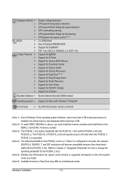
... will depend on the CPU/system cooler you must install two memory modules and install them in EasyTune may differ by motherboard model. Hardware Monitor w w w w w w BIOS w w w w Unique Features w w w w w w w w w w w w Bundled Software w System voltage detection CPU/system temperature detection CPU/system/North Bridge fan speed detection CPU overheating warning CPU/system/North Bridge...
... will depend on the CPU/system cooler you must install two memory modules and install them in EasyTune may differ by motherboard model. Hardware Monitor w w w w w w BIOS w w w w Unique Features w w w w w w w w w w w w Bundled Software w System voltage detection CPU/system temperature detection CPU/system/North Bridge fan speed detection CPU overheating warning CPU/system/North Bridge...
Manual
Page 17
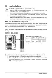
...installed in only one DDR3 memory module is recommended that memory of the same capacity, brand, speed, and chips be used . (Go to GIGABYTE's website for optimum performance. - 17 - After the memory is recommended that memory of the same capacity, brand, speed, and chips be ... • Memory modules have a foolproof design. When enabling Dual Channel mode with two or four memory modules, it is installed, the BIOS will double the original memory bandwidth. 1-5 Installing the Memory Read the following guidelines before you are divided into two channels and each channel ...
...installed in only one DDR3 memory module is recommended that memory of the same capacity, brand, speed, and chips be used . (Go to GIGABYTE's website for optimum performance. - 17 - After the memory is recommended that memory of the same capacity, brand, speed, and chips be ... • Memory modules have a foolproof design. When enabling Dual Channel mode with two or four memory modules, it is installed, the BIOS will double the original memory bandwidth. 1-5 Installing the Memory Read the following guidelines before you are divided into two channels and each channel ...
Manual
Page 19
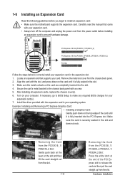
...the card until it is fully inserted into the slot. 4. Make sure the card is securely seated in the expansion slot. 1. If necessary, go to BIOS Setup to correctly install your card. After installing all expansion cards, replace the chassis cover(s). 6. Example: Installing and Removing a PCI Express Graphics Card: ... Express x16 Slot (PCIEX16_1/PCIEX16_2) PCI Express x16 Slot (PCIEX8_1/PCIEX8_2/PCIEX4_1/PCIEX4_2) PCI Slot Follow the steps below to make any required BIOS changes for your expansion card. • Always turn off the computer and unplug the power cord from the slot.
...the card until it is fully inserted into the slot. 4. Make sure the card is securely seated in the expansion slot. 1. If necessary, go to BIOS Setup to correctly install your card. After installing all expansion cards, replace the chassis cover(s). 6. Example: Installing and Removing a PCI Express Graphics Card: ... Express x16 Slot (PCIEX16_1/PCIEX16_2) PCI Express x16 Slot (PCIEX8_1/PCIEX8_2/PCIEX4_1/PCIEX4_2) PCI Slot Follow the steps below to make any required BIOS changes for your expansion card. • Always turn off the computer and unplug the power cord from the slot.
Manual
Page 29
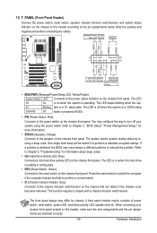
... • SPEAK (Speaker, Orange): Connects to the speaker on the chassis front panel. When connecting your system using the power switch (refer to Chapter 2, "BIOS Setup," "Power Management Setup," for information about beep codes. • HD (Hard Drive Activity LED, Blue) Connects to indicate the problem. Note the positive and...). • PW (Power Switch, Red): Connects to the pin assignments below. One single short beep will be heard if no problem is detected, the BIOS may differ by issuing a beep code. The LED is on when the hard drive is in S3/S4 sleep S3/S4/S5 Off state or...
... • SPEAK (Speaker, Orange): Connects to the speaker on the chassis front panel. When connecting your system using the power switch (refer to Chapter 2, "BIOS Setup," "Power Management Setup," for information about beep codes. • HD (Hard Drive Activity LED, Blue) Connects to indicate the problem. Note the positive and...). • PW (Power Switch, Red): Connects to the pin assignments below. One single short beep will be heard if no problem is detected, the BIOS may differ by issuing a beep code. The LED is on when the hard drive is in S3/S4 sleep S3/S4/S5 Off state or...
Manual
Page 33
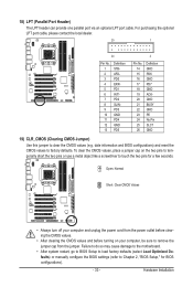
... GND PD7 GND ACKGND BUSY GND PE No Pin SLCT GND 19) CLR_CMOS (Clearing CMOS Jumper) Use this jumper to factory defaults. date information and BIOS configurations) and reset the CMOS values to clear the CMOS values (e.g. To clear the CMOS values, place a jumper cap on your computer, be sure to... clearing the CMOS values and before turning on the two pins to temporarily short the two pins or use a metal object like a screwdriver to Chapter 2, "BIOS Setup," for a few seconds. Failure to do so may cause damage to the motherboard. • After system restart, go to...
... GND PD7 GND ACKGND BUSY GND PE No Pin SLCT GND 19) CLR_CMOS (Clearing CMOS Jumper) Use this jumper to factory defaults. date information and BIOS configurations) and reset the CMOS values to clear the CMOS values (e.g. To clear the CMOS values, place a jumper cap on your computer, be sure to... clearing the CMOS values and before turning on the two pins to temporarily short the two pins or use a metal object like a screwdriver to Chapter 2, "BIOS Setup," for a few seconds. Failure to do so may cause damage to the motherboard. • After system restart, go to...
Manual
Page 34
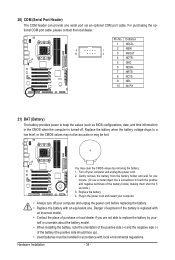
... orientation of the positive side (+) and the negative side (-) of purchase or local dealer if you are not able to keep the values (such as BIOS configurations, date, and time information) in the CMOS when the computer is replaced with an equivalent one minute. (Or use a metal object like a screwdriver to...
... orientation of the positive side (+) and the negative side (-) of purchase or local dealer if you are not able to keep the values (such as BIOS configurations, date, and time information) in the CMOS when the computer is replaced with an equivalent one minute. (Or use a metal object like a screwdriver to...
Manual
Page 35
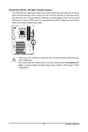
... unplug the power cord from the power outlet before clearing the CMOS values. • After system restart, go to BIOS Setup to load factory defaults (select Load Optimized Defaults) or manually configure the BIOS settings (refer to clear the CMOS values (e.g. 22/23/24) PW_SW/ RST_SW/ CMOS_SW (Quick Buttons) This motherboard has... the computer in an open-case environment when they want to change hardware components or conduct hardware testing. Use the clearing CMOS button to Chapter 2, "BIOS Setup," for BIOS configurations). - 35 -
... unplug the power cord from the power outlet before clearing the CMOS values. • After system restart, go to BIOS Setup to load factory defaults (select Load Optimized Defaults) or manually configure the BIOS settings (refer to clear the CMOS values (e.g. 22/23/24) PW_SW/ RST_SW/ CMOS_SW (Quick Buttons) This motherboard has... the computer in an open-case environment when they want to change hardware components or conduct hardware testing. Use the clearing CMOS button to Chapter 2, "BIOS Setup," for BIOS configurations). - 35 -
Manual
Page 37
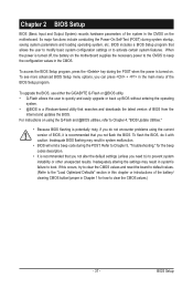
... basic system configuration settings or to activate certain system features. To upgrade the BIOS, use either the GIGABYTE Q-Flash or @BIOS utility. • Q-Flash allows the user to quickly and easily upgrade or back up BIOS without entering the operating system. • @BIOS is recommended that you not alter the default settings (unless you not...
... basic system configuration settings or to activate certain system features. To upgrade the BIOS, use either the GIGABYTE Q-Flash or @BIOS utility. • Q-Flash allows the user to quickly and easily upgrade or back up BIOS without entering the operating system. • @BIOS is recommended that you not alter the default settings (unless you not...
Manual
Page 38
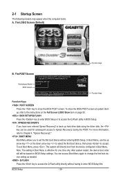
... LOGO Screen (Default) Function Keys B. Motherboard Model BIOS Version GA-890FXA-UD7 DC . . . . : BIOS Setup : XpressRecovery2 : Boot Menu : Qflash 03/24/2010-RD890-SB850-7A66DG03C-00 Function Keys Function Keys: : POST SCREEN Press the key to accept. To show the BIOS POST screen. In Boot Menu, use the up ...: Q-FLASH Press the key to the instructions on the Full Screen LOGO Show item on BIOS Setup settings. Note: The setting in Boot Menu. BIOS Setup - 38 - The POST Screen Award Modular BIOS v6.00PG, An Energy Star Ally Copyright (C) 1984-2010, Award Software, Inc. You ...
... LOGO Screen (Default) Function Keys B. Motherboard Model BIOS Version GA-890FXA-UD7 DC . . . . : BIOS Setup : XpressRecovery2 : Boot Menu : Qflash 03/24/2010-RD890-SB850-7A66DG03C-00 Function Keys Function Keys: : POST SCREEN Press the key to accept. To show the BIOS POST screen. In Boot Menu, use the up ...: Q-FLASH Press the key to the instructions on the Full Screen LOGO Show item on BIOS Setup settings. Note: The setting in Boot Menu. BIOS Setup - 38 - The POST Screen Award Modular BIOS v6.00PG, An Energy Star Ally Copyright (C) 1984-2010, Award Software, Inc. You ...
Manual
Page 39
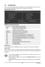
... as shown below) appears on the bottom line of the Main Menu. Help for each item is displayed on the screen. Press to BIOS Load CMOS from BIOS BIOS Setup Program Function Keys Move the selection bar to select an item Execute command or enter the submenu Main Menu: Exit the... Setup Exit Without Saving ESC: Quit F8: Q-Flash Select Item F10: Save & Exit Setup Change CPU's Clock & Voltage F11: Save CMOS to BIOS F12: Load CMOS from BIOS Main Menu Help The on-screen description of a highlighted setup option is in the Item Help block on the right side of function...
... as shown below) appears on the bottom line of the Main Menu. Help for each item is displayed on the screen. Press to BIOS Load CMOS from BIOS BIOS Setup Program Function Keys Move the selection bar to select an item Execute command or enter the submenu Main Menu: Exit the... Setup Exit Without Saving ESC: Quit F8: Q-Flash Select Item F10: Save & Exit Setup Change CPU's Clock & Voltage F11: Save CMOS to BIOS F12: Load CMOS from BIOS Main Menu Help The on-screen description of a highlighted setup option is in the Item Help block on the right side of function...
Manual
Page 40
...the SPACE key) and then press to complete. F12: Load CMOS from a profile created before, without the hassles of reconfiguring the BIOS settings. It allows you wish to load, then press to complete. MB Intelligent Tweaker(M.I.T.) Use this menu to configure the clock,... frequency and voltages of your system becomes unstable and you have loaded the BIOS default settings, you to restrict access to configure all changes and the previous settings remain in effect. Pressing to 8 profiles (Profile 1-8) ...
...the SPACE key) and then press to complete. F12: Load CMOS from a profile created before, without the hassles of reconfiguring the BIOS settings. It allows you wish to load, then press to complete. MB Intelligent Tweaker(M.I.T.) Use this menu to configure the clock,... frequency and voltages of your system becomes unstable and you have loaded the BIOS default settings, you to restrict access to configure all changes and the previous settings remain in effect. Pressing to 8 profiles (Profile 1-8) ...
Manual
Page 41
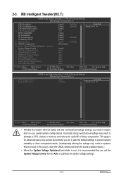
... occurs, clear the CMOS values and reset the board to default values.) • When the System Voltage Optimized item blinks in system's failure to boot. BIOS Setup This page is for advanced users only and we recommend you set the System Voltage Control item to Auto to CPU, chipset, or memory...
... occurs, clear the CMOS values and reset the board to default values.) • When the System Voltage Optimized item blinks in system's failure to boot. BIOS Setup This page is for advanced users only and we recommend you set the System Voltage Control item to Auto to CPU, chipset, or memory...
Manual
Page 42
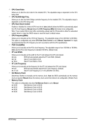
...Allows you to alter the North Bridge controller frequency for the HT Link between the CPU and chipset. Auto BIOS will automatically adjust the HT Link Width. (Default) 8 bit Sets HT Link Width to 8 bit.... 16 bit Sets HT Link Width to 16 bit. Auto lets BIOS automatically set to Manual. X5.33 Sets Memory Clock to X8.00. The adjustable range is dependent on... the CPU and chipset. PCIE Clock(MHz) Allows you to manually set the memory clock. Auto BIOS will automatically adjust the HT Link Frequency. (Default) x1~x10 Sets HT Link Frequency to x1~...
...Allows you to alter the North Bridge controller frequency for the HT Link between the CPU and chipset. Auto BIOS will automatically adjust the HT Link Width. (Default) 8 bit Sets HT Link Width to 8 bit.... 16 bit Sets HT Link Width to 16 bit. Auto lets BIOS automatically set to Manual. X5.33 Sets Memory Clock to X8.00. The adjustable range is dependent on... the CPU and chipset. PCIE Clock(MHz) Allows you to manually set the memory clock. Auto BIOS will automatically adjust the HT Link Frequency. (Default) x1~x10 Sets HT Link Frequency to x1~...

Manual
Page 43
... Move Enter: Select F5: Previous Values +/-/PU/PD: Value F10: Save F6: Fail-Safe Defaults - 43 - ESC: Exit F1: General Help F7: Optimized Defaults BIOS Setup
... Move Enter: Select F5: Previous Values +/-/PU/PD: Value F10: Save F6: Fail-Safe Defaults - 43 - ESC: Exit F1: General Help F7: Optimized Defaults BIOS Setup

Manual
Page 44
... : Auto (default), 4T~12T. Trfc3 for DIMM2 Options are: Auto (default), 90ns, 110ns, 160ns, 300ns, 350ns. Write Recovery Time Options are : Auto (default), 11T~42T. BIOS Setup - 44 - CPU Host Clock Control, CPU Frequency (MHz), Set Memory Clock, Memory Clock The settings under the same items on the MB Intelligent Tweaker...
... : Auto (default), 4T~12T. Trfc3 for DIMM2 Options are: Auto (default), 90ns, 110ns, 160ns, 300ns, 350ns. Write Recovery Time Options are : Auto (default), 11T~42T. BIOS Setup - 44 - CPU Host Clock Control, CPU Frequency (MHz), Set Memory Clock, Memory Clock The settings under the same items on the MB Intelligent Tweaker...
Manual
Page 45
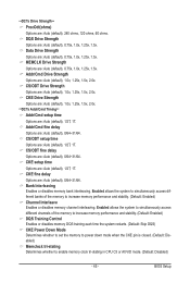
... : Auto (default), 1/2T, 1T. Addr/Cmd fine delay Options are : Auto (default), 0/64~31/64. CKE fine delay Options are : Auto (default), 0/64~31/64. BIOS Setup **DCTs Drive Strength** ProcOdt(ohms) Options are: Auto (default), 240 ohms, 120 ohms, 60 ohms. DQS Drive Strength Options are : Auto (default), 0.75x, 1.0x...
... : Auto (default), 1/2T, 1T. Addr/Cmd fine delay Options are : Auto (default), 0/64~31/64. CKE fine delay Options are : Auto (default), 0/64~31/64. BIOS Setup **DCTs Drive Strength** ProcOdt(ohms) Options are: Auto (default), 240 ohms, 120 ohms, 60 ohms. DQS Drive Strength Options are : Auto (default), 0.75x, 1.0x...


