Manual
Page 3
..., or published in the use GIGABYTE's unique features, read the User's Manual. Copyright © 2010 GIGA-BYTE TECHNOLOGY CO., LTD. All rights reserved. No part of this manual is protected by any means without prior notice. For detailed product information, carefully read or download the information on/from the Support&Downloads\Motherboard\Technology Guide page on your motherboard revision before updating motherboard BIOS, drivers, or when looking for technical...
..., or published in the use GIGABYTE's unique features, read the User's Manual. Copyright © 2010 GIGA-BYTE TECHNOLOGY CO., LTD. All rights reserved. No part of this manual is protected by any means without prior notice. For detailed product information, carefully read or download the information on/from the Support&Downloads\Motherboard\Technology Guide page on your motherboard revision before updating motherboard BIOS, drivers, or when looking for technical...
Manual
Page 4
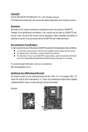
...Dual Channel Memory Configuration 17 1-5-2 Installing a Memory 18 1-6 Installing an Expansion Card 19 1-7 Setting up ATI CrossFireX™ Configuration 20 1-8 Installing the SATA Bracket 21 1-9 Back Panel Connectors 22 1-10 Internal Connectors 24 Chapter 2 BIOS Setup 37 2-1 Startup Screen 38 2-2 The Main Menu 39 2-3 MB Intelligent Tweaker(M.I.T 41 2-4 Standard CMOS Features 47 2-5 Advanced BIOS Features 49 2-6 Integrated Peripherals 51 2-7 Power Management Setup 55 2-8 PC Health Status 57 2-9 Load Fail-Safe Defaults 59 2-10 Load Optimized Defaults 59 2-11 Set Supervisor/User...
...Dual Channel Memory Configuration 17 1-5-2 Installing a Memory 18 1-6 Installing an Expansion Card 19 1-7 Setting up ATI CrossFireX™ Configuration 20 1-8 Installing the SATA Bracket 21 1-9 Back Panel Connectors 22 1-10 Internal Connectors 24 Chapter 2 BIOS Setup 37 2-1 Startup Screen 38 2-2 The Main Menu 39 2-3 MB Intelligent Tweaker(M.I.T 41 2-4 Standard CMOS Features 47 2-5 Advanced BIOS Features 49 2-6 Integrated Peripherals 51 2-7 Power Management Setup 55 2-8 PC Health Status 57 2-9 Load Fail-Safe Defaults 59 2-10 Load Optimized Defaults 59 2-11 Set Supervisor/User...
Manual
Page 20
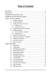
... Windows 7 operating systems only - A power supply with your graphics cards for more information about enabling CrossFireX technology. (Note) The bridge connectors may differ by graphics cards. The following table shows the recommended CrossFireX configurations with two/three/four PCI Express x16 slots and correct driver - Click OK to apply. Click OK to apply. Refer to the manual that support 3-Way/4-Way CrossFireX technology include the Radeon HD 3800 series...
... Windows 7 operating systems only - A power supply with your graphics cards for more information about enabling CrossFireX technology. (Note) The bridge connectors may differ by graphics cards. The following table shows the recommended CrossFireX configurations with two/three/four PCI Express x16 slots and correct driver - Click OK to apply. Click OK to apply. Refer to the manual that support 3-Way/4-Way CrossFireX technology include the Radeon HD 3800 series...
Manual
Page 26
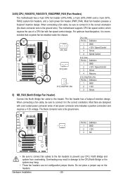
... may result in the correct orientation. Hardware Installation - 26 - 3/4/5) CPU_FAN/SYS_FAN1/SYS_FAN2/PWR_FAN (Fan Headers) The motherboard has a 4-pin CPU fan header (CPU_FAN), a 4-pin (SYS_FAN1) and a 3-pin (SYS_ FAN2) system fan headers, and a 3-pin power fan header (PWR_FAN). The motherboard supports CPU fan speed control, which requires the use of a CPU fan with color-coded power connector wires. Definition 1 GND 2 +12V 3 Sense 6) NB_FAN (North Bridge Fan Header) Connect the North Bridge fan cable to this header. Most fans are not configuration jumper blocks. Pin No.
... may result in the correct orientation. Hardware Installation - 26 - 3/4/5) CPU_FAN/SYS_FAN1/SYS_FAN2/PWR_FAN (Fan Headers) The motherboard has a 4-pin CPU fan header (CPU_FAN), a 4-pin (SYS_FAN1) and a 3-pin (SYS_ FAN2) system fan headers, and a 3-pin power fan header (PWR_FAN). The motherboard supports CPU fan speed control, which requires the use of a CPU fan with color-coded power connector wires. Definition 1 GND 2 +12V 3 Sense 6) NB_FAN (North Bridge Fan Header) Connect the North Bridge fan cable to this header. Most fans are not configuration jumper blocks. Pin No.
Manual
Page 35
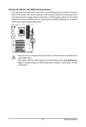
... Buttons) This motherboard has 3 quick buttons: power button, clearing CMOS button and reset button. Use the clearing CMOS button to Chapter 2, "BIOS Setup," for BIOS configurations). - 35 - date information and BIOS configurations) and reset the CMOS values to factory defaults when needed. • Always turn on/off your computer and unplug the power cord from the power outlet before clearing the CMOS values. • After system restart, go to BIOS Setup to load factory defaults (select Load Optimized Defaults) or manually configure the BIOS settings (refer to clear the CMOS...
... Buttons) This motherboard has 3 quick buttons: power button, clearing CMOS button and reset button. Use the clearing CMOS button to Chapter 2, "BIOS Setup," for BIOS configurations). - 35 - date information and BIOS configurations) and reset the CMOS values to factory defaults when needed. • Always turn on/off your computer and unplug the power cord from the power outlet before clearing the CMOS values. • After system restart, go to BIOS Setup to load factory defaults (select Load Optimized Defaults) or manually configure the BIOS settings (refer to clear the CMOS...
Manual
Page 38
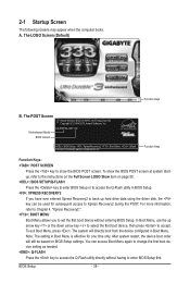
... subsequent access to accept. Motherboard Model BIOS Version GA-890FXA-UD7 DC . . . . : BIOS Setup : XpressRecovery2 : Boot Menu : Qflash 03/24/2010-RD890-SB850-7A66DG03C-00 Function Keys Function Keys: : POST SCREEN Press the key to show the BIOS POST screen at system startup, refer to the instructions on the Full Screen LOGO Show item on BIOS Setup settings. You can be based on page 50. : BIOS SETUP\Q-FLASH Press the key to enter BIOS Setup or to access the Q-Flash utility in Boot Menu. 2-1 Startup Screen The following screens...
... subsequent access to accept. Motherboard Model BIOS Version GA-890FXA-UD7 DC . . . . : BIOS Setup : XpressRecovery2 : Boot Menu : Qflash 03/24/2010-RD890-SB850-7A66DG03C-00 Function Keys Function Keys: : POST SCREEN Press the key to show the BIOS POST screen at system startup, refer to the instructions on the Full Screen LOGO Show item on BIOS Setup settings. You can be based on page 50. : BIOS SETUP\Q-FLASH Press the key to enter BIOS Setup or to access the Q-Flash utility in Boot Menu. 2-1 Startup Screen The following screens...
Manual
Page 40
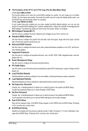
... menu to configure the device boot order, advanced features available on the CPU, and the primary display adapter. Integrated Peripherals Use this menu to configure all peripheral devices, such as IDE, SATA, USB, integrated audio, and integrated LAN, etc. Power Management Setup Use this menu to configure all the power-saving functions. PC Health Status Use this menu to see information about autodetected system/CPU temperature, system voltage and fan speed, etc. Load Fail-Safe Defaults Fail-Safe defaults...
... menu to configure the device boot order, advanced features available on the CPU, and the primary display adapter. Integrated Peripherals Use this menu to configure all peripheral devices, such as IDE, SATA, USB, integrated audio, and integrated LAN, etc. Power Management Setup Use this menu to configure all the power-saving functions. PC Health Status Use this menu to see information about autodetected system/CPU temperature, system voltage and fan speed, etc. Load Fail-Safe Defaults Fail-Safe defaults...
Manual
Page 42
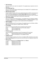
... clear the CMOS values to reset the board to X6.66. Auto lets BIOS automatically set the memory clock. Allows you to manually set the memory clock as required. The adjustable range is set the PCIe clock frequency. This option is configurable only when CPU Host Clock Control is dependent on the CPU being used . PCIE Clock(MHz) Allows you to Manual. Auto sets the PCIe clock frequency to standard 100 MHz. (Default: Auto) HT Link Width Allows you to manually set to manually set the frequency for the installed CPU...
... clear the CMOS values to reset the board to X6.66. Auto lets BIOS automatically set the memory clock. Allows you to manually set the memory clock as required. The adjustable range is set the PCIe clock frequency. This option is configurable only when CPU Host Clock Control is dependent on the CPU being used . PCIE Clock(MHz) Allows you to Manual. Auto sets the PCIe clock frequency to standard 100 MHz. (Default: Auto) HT Link Width Allows you to manually set to manually set the frequency for the installed CPU...
Manual
Page 45
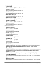
... memory performance and stability. (Default: Enabled) DQS Training Control Enables or disables memory DQS training each time the system restarts. (Default: Skip DQS) CKE Power Down Mode Determines whether to set the memory to power down mode when the CKE pin is closed. (Default: Disabled) Memclock tri-stating Determines whether to increase memory performance and stability. (Default: Enabled) Channel Interleave Enables or disables memory channel interleaving. BIOS Setup CS/ODT Drive Strength Options are : Auto (default), 1/2T, 1T. CKE setup time Options are : Auto (default...
... memory performance and stability. (Default: Enabled) DQS Training Control Enables or disables memory DQS training each time the system restarts. (Default: Skip DQS) CKE Power Down Mode Determines whether to set the memory to power down mode when the CKE pin is closed. (Default: Disabled) Memclock tri-stating Determines whether to increase memory performance and stability. (Default: Enabled) Channel Interleave Enables or disables memory channel interleaving. BIOS Setup CS/ODT Drive Strength Options are : Auto (default), 1/2T, 1T. CKE setup time Options are : Auto (default...
Manual
Page 49
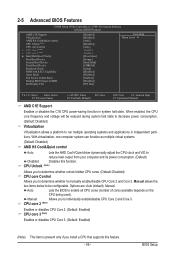
...are: Auto (default), Manual. Capability Away Mode Full Screen LOGO Show Backup BIOS Image to enable all CPU cores (number of cores available depends on the CPU being used). 2-5 Advanced BIOS Features CMOS Setup Utility-Copyright (C) 1984-2010 Award Software Advanced BIOS Features AMD C1E Support Virtualization AMD K8 Cool&Quiet control CPU Unlock (Note) CPU core Control x CPU core 2 (Note) x CPU core 3 (Note) } Hard Disk Boot Priority First Boot Device Second Boot Device Third Boot Device Password Check HDD S.M.A.R.T. BIOS Setup...
...are: Auto (default), Manual. Capability Away Mode Full Screen LOGO Show Backup BIOS Image to enable all CPU cores (number of cores available depends on the CPU being used). 2-5 Advanced BIOS Features CMOS Setup Utility-Copyright (C) 1984-2010 Award Software Advanced BIOS Features AMD C1E Support Virtualization AMD K8 Cool&Quiet control CPU Unlock (Note) CPU core Control x CPU core 2 (Note) x CPU core 3 (Note) } Hard Disk Boot Priority First Boot Device Second Boot Device Third Boot Device Password Check HDD S.M.A.R.T. BIOS Setup...
Manual
Page 50
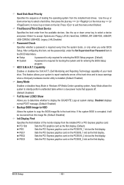
...entering the BIOS Setup program. Disabled displays normal POST message. (Default: Enabled) Backup BIOS Image to HDD Allows the system to copy the BIOS image file to exit this menu when finished. BIOS Setup - 50 - First/Second/Third Boot Device Specifies the boot order from the installed hard drives. Options are: Floppy, LS120, Hard Disk, CDROM, ZIP, USB-FDD, USB-ZIP, USB-CDROM, USB-HDD, Legacy LAN, Disabled. After configuring this image file. (Default: Disabled) Init Display First Specifies the first initiation of the monitor display from the installed PCI or PCI Express graphics...
...entering the BIOS Setup program. Disabled displays normal POST message. (Default: Enabled) Backup BIOS Image to HDD Allows the system to copy the BIOS image file to exit this menu when finished. BIOS Setup - 50 - First/Second/Third Boot Device Specifies the boot order from the installed hard drives. Options are: Floppy, LS120, Hard Disk, CDROM, ZIP, USB-FDD, USB-ZIP, USB-CDROM, USB-HDD, Legacy LAN, Disabled. After configuring this image file. (Default: Disabled) Init Display First Specifies the first initiation of the monitor display from the installed PCI or PCI Express graphics...
Manual
Page 51
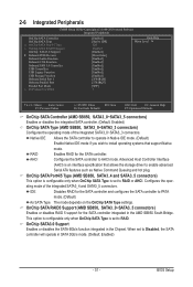
...AMD SB850 South Bridge. 2-6 Integrated Peripherals CMOS Setup Utility-Copyright (C) 1984-2010 Award Software Integrated Peripherals OnChip SATA Controller OnChip SATA Type x OnChip SATA Port4/5 Type x OnChip SATA RAID5 Support OnChip SATA3.0 Support } Onboard PCIE Devices Onboard Audio Function Onboard 1394 Function Onboard USB 3.0 Controller USB Controllers USB Legacy Function USB Storage Function Onboard Serial Port 1 Onboard Parallel Port Parallel Port Mode x ECP Mode Use DMA [Enabled] [Native IDE] IDE Enabled [Enabled] [Press Enter] [Enabled...
...AMD SB850 South Bridge. 2-6 Integrated Peripherals CMOS Setup Utility-Copyright (C) 1984-2010 Award Software Integrated Peripherals OnChip SATA Controller OnChip SATA Type x OnChip SATA Port4/5 Type x OnChip SATA RAID5 Support OnChip SATA3.0 Support } Onboard PCIE Devices Onboard Audio Function Onboard 1394 Function Onboard USB 3.0 Controller USB Controllers USB Legacy Function USB Storage Function Onboard Serial Port 1 Onboard Parallel Port Parallel Port Mode x ECP Mode Use DMA [Enabled] [Native IDE] IDE Enabled [Enabled] [Press Enter] [Enabled...

Manual
Page 52
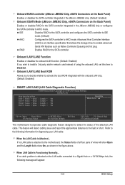
...installed. (Default) X16 PCIEX16_2 operates at x4 mode. Onboard PCIE Devices CMOS Setup Utility-Copyright (C) 1984-2010 Award Software Onboard PCIE Devices Primary Dual Slot Config Secondary Dual Slot Config PCIEX4_2 Slot Config [Auto] [Auto] [As X1 Link] Item Help Menu Level Onboard GSATA controller Onboard GSATA Mode Onboard ESATA controller Onboard ESATA Mode [Enabled] [IDE] [Enabled] [IDE] Onboard LAN1 Function Onboard LAN1 Boot ROM } SMART LAN1 Onboard LAN2 Function Onboard LAN2 Boot ROM } SMART LAN2 [Enabled] [Disabled] [Press Enter...
...installed. (Default) X16 PCIEX16_2 operates at x4 mode. Onboard PCIE Devices CMOS Setup Utility-Copyright (C) 1984-2010 Award Software Onboard PCIE Devices Primary Dual Slot Config Secondary Dual Slot Config PCIEX4_2 Slot Config [Auto] [Auto] [As X1 Link] Item Help Menu Level Onboard GSATA controller Onboard GSATA Mode Onboard ESATA controller Onboard ESATA Mode [Enabled] [IDE] [Enabled] [IDE] Onboard LAN1 Function Onboard LAN1 Boot ROM } SMART LAN1 Onboard LAN2 Function Onboard LAN2 Boot ROM } SMART LAN2 [Enabled] [Disabled] [Press Enter...
Manual
Page 53
... whether to AHCI mode. IDE Disables RAID for the SATA controller integrated in the figure above. This feature will appear: - 53 - BIOS Setup If no cable problem is an interface specification that allows the storage driver to enable advanced Serial ATA features such as shown in the JMicron JMB362 chip or configures the SATA controller to activate the boot ROM integrated with the onboard LAN chip. (Default: Disabled) SMART LAN1/LAN2 (LAN Cable Diagnostic Function) CMOS Setup Utility-Copyright (C) 1984-2010 Award Software SMART LAN Start detecting at Port.....
... whether to AHCI mode. IDE Disables RAID for the SATA controller integrated in the figure above. This feature will appear: - 53 - BIOS Setup If no cable problem is an interface specification that allows the storage driver to enable advanced Serial ATA features such as shown in the JMicron JMB362 chip or configures the SATA controller to activate the boot ROM integrated with the onboard LAN chip. (Default: Disabled) SMART LAN1/LAN2 (LAN Cable Diagnostic Function) CMOS Setup Utility-Copyright (C) 1984-2010 Award Software SMART LAN Start detecting at Port.....

Manual
Page 54
...) USB Controllers Enables or disables the integrated USB controllers. (Default: Enabled) Disabled will only operate at a normal speed of using the onboard audio, set to detect USB storage devices, including USB flash drives and USB hard drives during the POST. (Default: Enabled) Onboard Serial Port 1 Enables or disables the first serial port and specifies its base I /O address and corresponding interrupt. ECP Mode Use DMA Selects DMA channel for the onboard parallel (LPT) port. Parallel Port Mode Selects an operating mode for the LPT port in Windows mode or when the LAN Boot ROM...
...) USB Controllers Enables or disables the integrated USB controllers. (Default: Enabled) Disabled will only operate at a normal speed of using the onboard audio, set to detect USB storage devices, including USB flash drives and USB hard drives during the POST. (Default: Enabled) Onboard Serial Port 1 Enables or disables the first serial port and specifies its base I /O address and corresponding interrupt. ECP Mode Use DMA Selects DMA channel for the onboard parallel (LPT) port. Parallel Port Mode Selects an operating mode for the LPT port in Windows mode or when the LAN Boot ROM...

Manual
Page 87
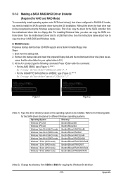
... your power supply to the hard drive. See the table below for configuring different SATA controllers for the SATA controllers and their corresponding SATA ports. Go to RAID CMOS Setup Utility-Copyright (C) 1984-2010 Award Software Onboard PCIE Devices Primary Dual Slot Config Secondary Dual Slot Config PCIEX4_2 Slot Config [Auto] [Auto] [As X1 Link] Item Help Menu Level Onboard GSATA controller Onboard GSATA Mode Onboard ESATA controller Onboard ESATA Mode [Enabled] [RAID/IDE] [Enabled] [RAID] Onboard LAN1 Function Onboard LAN1 Boot ROM } SMART LAN1...
... your power supply to the hard drive. See the table below for configuring different SATA controllers for the SATA controllers and their corresponding SATA ports. Go to RAID CMOS Setup Utility-Copyright (C) 1984-2010 Award Software Onboard PCIE Devices Primary Dual Slot Config Secondary Dual Slot Config PCIEX4_2 Slot Config [Auto] [Auto] [As X1 Link] Item Help Menu Level Onboard GSATA controller Onboard GSATA Mode Onboard ESATA controller Onboard ESATA Mode [Enabled] [RAID/IDE] [Enabled] [RAID] Onboard LAN1 Function Onboard LAN1 Boot ROM } SMART LAN1...
Manual
Page 93
... Windows 7 32-bit (RAID mode) Bootdrv\SBxxxW7\RAID\W7 Windows 7 64-bit (AHCI mode) Bootdrv\SBxxxW7\AHCI\Win7x64 Windows 7 64-bit (RAID mode) Bootdrv\SBxxxW7\RAID\W764A (Note 2) Change the directory from \32bit to \64bit for the SATA controller from the motherboard driver disk to install the SATA controller driver during the Windows setup process. Refer to the following command. First of all, copy the driver for copying the Windows 64-bit driver. - 93 - For installing Windows Vista, you need to a floppy disk. Appendix Steps: 1: Boot...
... Windows 7 32-bit (RAID mode) Bootdrv\SBxxxW7\RAID\W7 Windows 7 64-bit (AHCI mode) Bootdrv\SBxxxW7\AHCI\Win7x64 Windows 7 64-bit (RAID mode) Bootdrv\SBxxxW7\RAID\W764A (Note 2) Change the directory from \32bit to \64bit for the SATA controller from the motherboard driver disk to install the SATA controller driver during the Windows setup process. Refer to the following command. First of all, copy the driver for copying the Windows 64-bit driver. - 93 - For installing Windows Vista, you need to a floppy disk. Appendix Steps: 1: Boot...

Manual
Page 96
... proceed with Windows, using a device support disk provided by an adapter manufacturer. Select RAID/AHCI Driver for use with the Windows XP installation. Windows Setup You have chosen to the previous screen. After the driver installation, you want from the following list, or press ESC to return to configure a SCSI Adapter for GIGABYTE GBB36X Controller (x32) and press . Appendix - 96 - Then a controller menu similar to continue the driver installation. RAID/AHCI Driver for GIGABYTE GBB36X Controller (x32) ENTER=Select F3...
... proceed with Windows, using a device support disk provided by an adapter manufacturer. Select RAID/AHCI Driver for use with the Windows XP installation. Windows Setup You have chosen to the previous screen. After the driver installation, you want from the following list, or press ESC to return to configure a SCSI Adapter for GIGABYTE GBB36X Controller (x32) and press . Appendix - 96 - Then a controller menu similar to continue the driver installation. RAID/AHCI Driver for GIGABYTE GBB36X Controller (x32) ENTER=Select F3...
Manual
Page 112
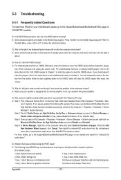
... on Microsoft UAA Bus Driver for your motherboard, please go to the Support&Downloads\Motherboard\FAQ page on GIGABYTE's website. A: The following Award BIOS beep code descriptions may help you identify possible computer problems. (For reference only.) 1 short: System boots successfully 1 long, 3 short: Keyboard error 2 short: CMOS setting error 1 long, 9 short: BIOS ROM error 1 long, 1 short: Memory or motherboard error Continuous long beeps: Graphics card not inserted properly 1 long, 2 short: Monitor or graphics card error Continuous short beeps: Power error Appendix - 112...
... on Microsoft UAA Bus Driver for your motherboard, please go to the Support&Downloads\Motherboard\FAQ page on GIGABYTE's website. A: The following Award BIOS beep code descriptions may help you identify possible computer problems. (For reference only.) 1 short: System boots successfully 1 long, 3 short: Keyboard error 2 short: CMOS setting error 1 long, 9 short: BIOS ROM error 1 long, 1 short: Memory or motherboard error Continuous long beeps: Graphics card not inserted properly 1 long, 2 short: Monitor or graphics card error Continuous short beeps: Power error Appendix - 112...
Manual
Page 117
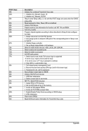
... key is supported - Clear EPA or customization logo 1. USB final Initialization 2. Invoke all PCI ROMs (except VGA) 1. Initialize floppy controller 2. If errors occur, report errors & wait for Trend Anti-Virus code - 117 - Initialize Init_Onbaord_AUDIO Okay to CMOS setup 2. Enable/Disable Parity Check according to enter Setup utility; Set up ACPI table at top of IRQs Read HDD boot sector information for keys - If password is set , ask for full screen logo) 3. APM initialization Clear noise of the memory 1. Call chipset power...
... key is supported - Clear EPA or customization logo 1. USB final Initialization 2. Invoke all PCI ROMs (except VGA) 1. Initialize floppy controller 2. If errors occur, report errors & wait for Trend Anti-Virus code - 117 - Initialize Init_Onbaord_AUDIO Okay to CMOS setup 2. Enable/Disable Parity Check according to enter Setup utility; Set up ACPI table at top of IRQs Read HDD boot sector information for keys - If password is set , ask for full screen logo) 3. APM initialization Clear noise of the memory 1. Call chipset power...


